manuals.online logo
Brands
  1. Home
  2. •
  3. Brands
  4. •
  5. Siemens
  6. •
  7. Controllers
  8. •
  9. Siemens GBB 2 Series User manual

Siemens GBB 2 Series User manual

Siemens Building Technologies / Landis & Staefa Division 74 319 2686 0 c 03.09.1999 1/8
ALieferumfang
Supply
Contenu
Leverans
Leveringsomvang
Contenuto
Toimituslaajuus
Contenido
Leverancens omfang
Zawartość
4656Z05
BHinweise / Warnungen
Hints / Warnings
Indications / Mise en garde
Hänvisningar / Varningar
Aanwijzingen / Waarschuwingen
Messa in servizio / Indicazioni
Huomauksia / Varoituksia
Indicaciones / Consejos
Bemærkninger / Advarsler
Wskazówki / Ostrzeżenia
4656Z06
<45°
<45°
90°
ASK75.2
IP54
M4656
4 319 2686 0
de Montageanleitung Hubantrieb
en Mounting instructions Linear-type actuator
fr Instructions de montage Servo-moteur à action linéaire
sv Monteringsinstruktion Spjällställdon med linjär rörelse
nl Montage-aanwijzing Luchtklepservomotor voor lineare aandrijving
it Istruzioni di montaggio Servocomando lineare
fi Asennusohje Työntöliikkeinen ilmapeltien toimimoottori
es Instrucciones de montaje Actuador de acción lineal
da Monteringsvejledning Motor for lineær bevægelse
pl Instrukcja montażuSiłownik liniowy GBB...2
2/8 03.09.1999 74 319 2686 0 c Siemens Building Technologies / Landis & Staefa Division
de sv fi
Diese Anleitung ist beim Antrieb oder in der
Anlagendokumentation aufzubewahren!
Elektrisches Anschliessen von Antrieben für
AC 230 V ist nur durch autorisiertes Personal
gestattet.
Achtung! Der Stellantrieb darf nicht
geöffnet werden.
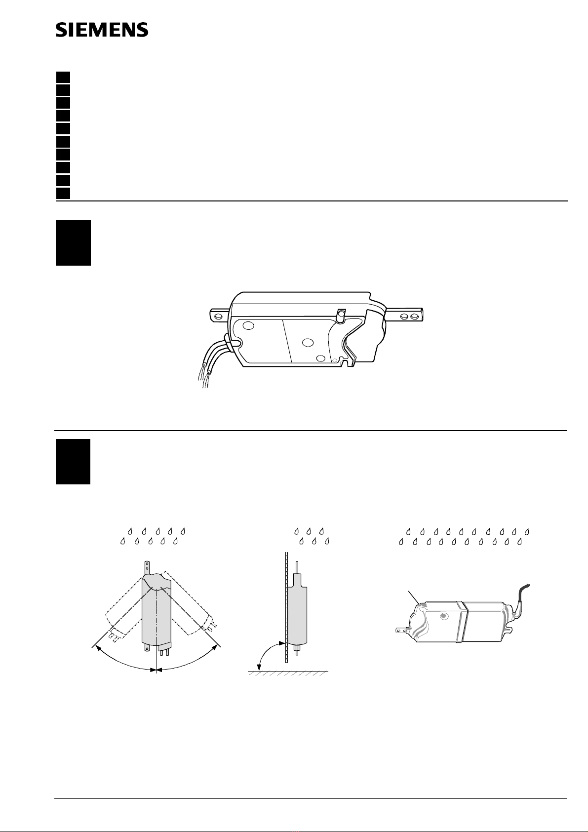
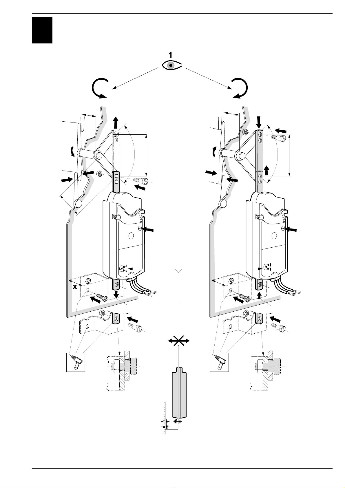
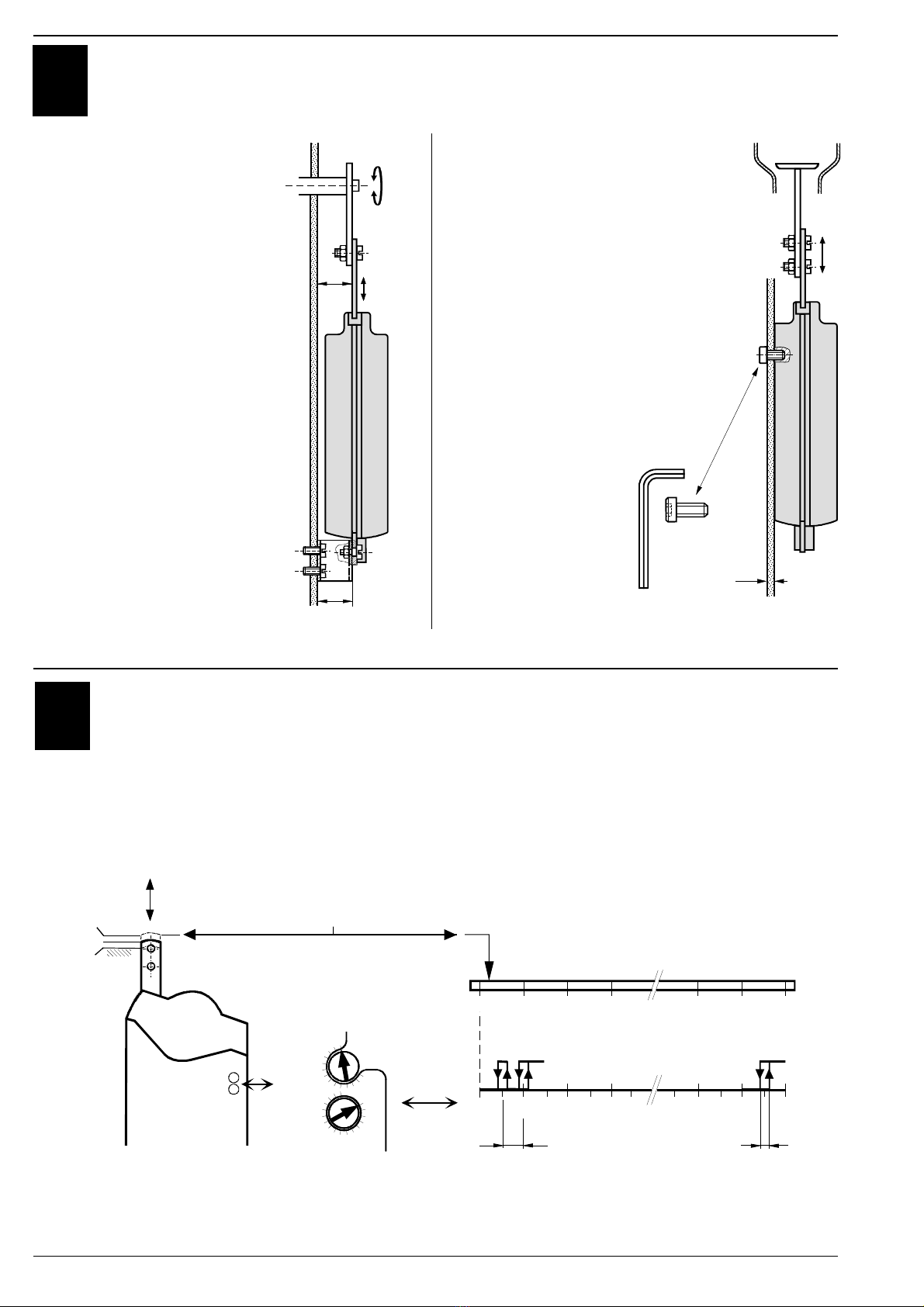
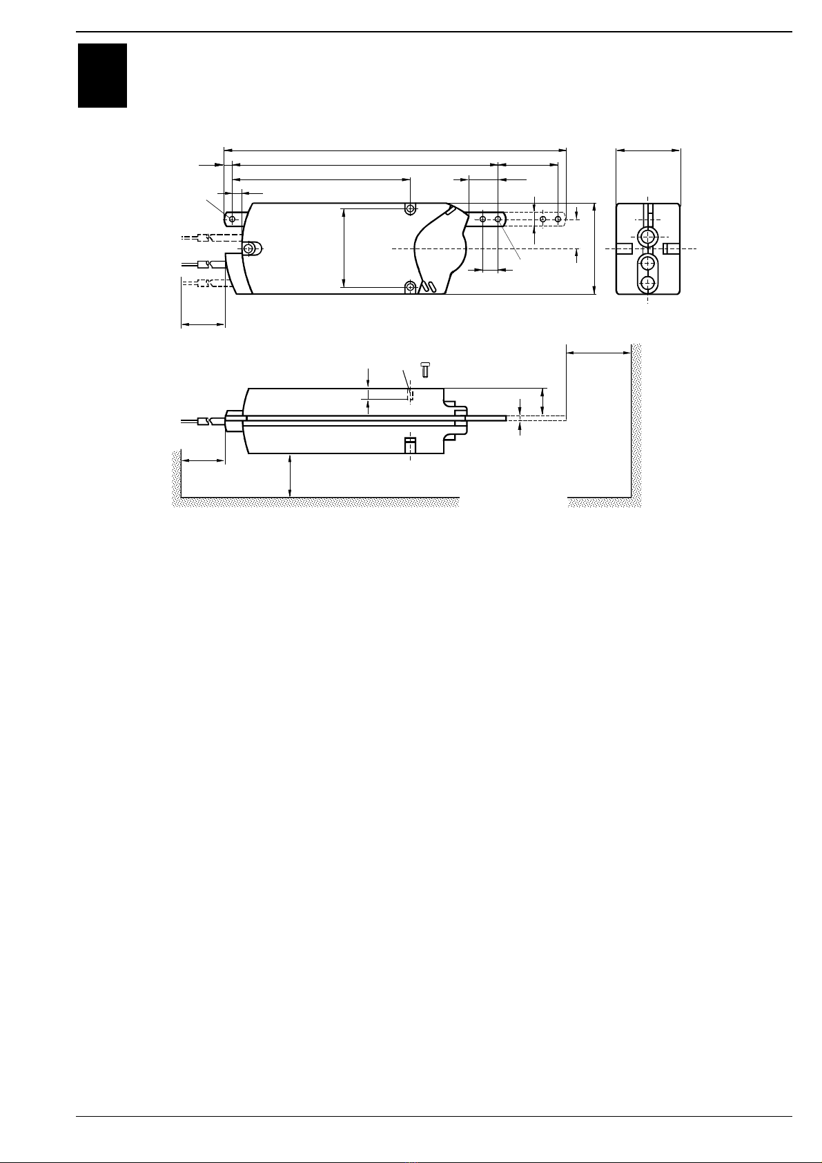
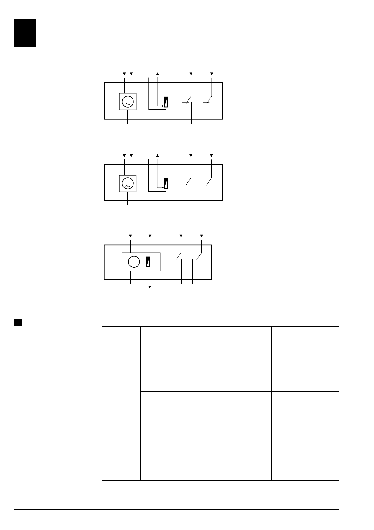
Verdrahtung und Inbetriebnahme
Siehe in den anlagenspezifischen Unterlagen und
im Fachblatt zum Antrieb.
Denna instruktion skall förvaras tillsammans
med ställdonet eller anläggningsdokumentet!
Elektrisk installation av ställdon med 230 V
AC får endast utföras av behörig servicetekniker.
OBS! Ställdonet får inte öppnas.
Elektrisk inkoppling och igångkörning
Se anläggningsspecifika underlag och datablad
för ställdonet.
Tätä ohjetta tulee säilyttää toimimoottorin
läheisyydessä tai yhdessä laitosdokumenttien
kanssa!
Ainoastaan asiaankuuluvat oikeudet
omaavat henkilöt saavat tehdä käyttöjännitteen
230 V AC liitäntätöitä.
Huomio! Toimimoottoria ei saa avata.
Johdotus ja käyttöönotto
Katso laitoskohtaisista dokumenteista ja toimi-
moottorin esitteestä.
en nl es
Keep this instruction guide together with the
actuator or with the plant documentation!
Only authorized personnel may perform
electrical connections for AC 230 V.
Attention! Do not open the actuator.
Wiring and commissioning
See the commissioning instructions and the data
sheet for the actuator.
Deze handleiding moet bij de servomotor, of
met de documentatie van de installatie worden
bewaard.
De elektrisch aansluitning van servomotoren
voor 230 V AC mag alleen door geautoriseerd
personeel worden uitgevoerd.
Opgelet! De servomotor mag niet worden
geopend.
Bekabeling en inbedrijfstelling
Raadpleeg de installatie-documentatie en het
apparatenblad voor de servomotor.
Conserve estas instrucciones con el actuador
o con la documentación de la instalación!
La conexión eléctrica del actuador a
230 V CA debe hacerse solamente por personal
autorizado.
Atención! el actuador no debe ser abierto.
Cableado y puesta en marcha
Ver la documen-tación de la instalación y la hoja
técnica del actuador.
fr it da
Cette instruction est à conserver avec le
servo-moteur ou avec la documentation de
l’installation!
Le raccordement électrique de servo-moteur
pour le AC 230 V ne peut être effectué que par du
personnel autorisé.
Attention! Le servo-moteur ne doit pas être
ouvert.
Câblage et mise en service
Voir la documentation de l’installation et la feuille
technique de servo-moteur.
Queste istruzioni devono essere conservate
con la documentazione dell’impianto!
I collegamenti a 230 V c.a. devono essere
eseguiti da personale autorizzato.
Attenzione! Il servocomando non deve
essere aperto.
Collegamenti e messa in servizio
Consultare la documentazione dell’impianto e il
foglio tecnico.
Opbevar denne vejledning sammen med
motoren eller med anlægsdokumentationen!
Elektrisk tilslutning af motorer for AC 230 V
må kun foretages af autoriserede personer.
OBS! Motoren må ikke åbnes.
Eltilslutning og idriftsættelse
Se den anlægsspecifikke dokumentation og
katalogbladet for motoren.
pl
Należy przechowywaćtąinstrukcjęrazem z
siłownikiem lub z dokumentacjąinstalacji!
Tylko upoważniony personel może
wykonywaćpołączenia elektryczne na poziomie
230 V AC.
Uwaga! Nie otwieraćsiłownika.
Połączenia i rozruch
Patrz instrukcje rozruchowe i karta katalogowa
siłownika
Siemens Building Technologies / Landis & Staefa Division 74 319 2686 0 c 03.09.1999 3/8
CAdapter-Montage
Adapter Mounting
Montage de l’adapteur
Montering av adapter
Apadper-montage
Montaggio dell’adattatore
Sovittimen asennus
Montaje del adaptador
Montering af adapter
Montażadaptera
90°
x
(50)
max.75
90°
810
3
3
5
6
4
4656Z02
4/9
7
22
6
57
8
PUSH PUSH
nur für
only for
tylko dla
GBB16...
max. 880 N max. 880 N
7
5
max.75
x
x
WCIŚNIJ WCIŚNIJ
Masse in mm Mått i mm Mitat mm
Dimensions in mm Afmetingen in mm Dimensiones en mm
Dimensions en mm Dimensioni in mm Mål i mm
Wymiary w mm
4/8 03.09.1999 74 319 2686 0 c Siemens Building Technologies / Landis & Staefa Division
DAnwendung
Application
Application
Användning
Toepassing
Applicazioni
Käyttö
Aplicación
Anvendelse
Zastosowanie
•für Drehklappen
•for rotary damper
•pour volets à commande par rotation
•för spjäll med vridande rörelse
•Voor roterende kleppen
•per serrande a comando rotativo
•kiertoliikepeltien kanssa
•Para compuertas rotativas
•for drejespjæld
•do przepustnic obrotowych
X =
min. 35
4656Z03
X
•für Hubklappen
•for linear damper
•pour volets à
commande lineaire
•för spjäll med linjär rörelse
•Voor roterende kleppen
•per serrande a
comando lineare
•työntöliikepeltien kanssa
•Para compuertas lineales
•for spjæld for
lineær bevægelse
•do przepustnic liniowych
4656Z01
2...6
5 mm
2 x Taptite
M6 x 16
EEinstellung: Hilfsschalter A, B
Setting: Auxiliary switch A, B
Réglage: Contact auxiliaire A, B
Inställning: Hjälpkontakt A, B
Instelling: Hulpschakelaar A, B
Taratura: Contatto ausiliaro A, B
Asettelu: Apukytkin A, B
Ajuste: Contacto auxiliar A, B
Indstilling: Hjælpekontakt A, B
Nastawy: Przełączniki A, B
2
4656Z07
4
1
16
24
32
B8
Aux Switch
Adjustment
mm
56
48
40
64
56
40
A
16
48
B
-2 0816
24 56 64 72
0 8 16 24 56 64 72
mm
mm
+2
A
A
B
+ 2
0
- 2
B'
2
h
h
Werkeinstellung
Factory setting
Préreglé à l'usine
Fabriksinställning
Fabrieksmatig ingestelde
Alla consegna
Tehdasasetus
Ajuste de fábrica
Fabriksindstillet
Nastawa fabryczna
Siemens Building Technologies / Landis & Staefa Division 74 319 2686 0 c 03.09.1999 5/8
FMassbild
Dimensions
Encombrement
Måttuppgift
Maatschets
Ingombri
Mittapiirros
Dimensiones
Målskitse
Wymiary
373
283
5
4656M01
7,5
193
10,9
85,8
28,4
max. 75
15
15
30,9
100
29,3
67,5
min. 60
900
min. 200
min. 100
15
ø 5,7 Taptite
M6 x 16
P1...P3
S1...S6
1...9 ø 6,1
ø 6,1
Masse in mm Mått i mm Mitat mm
Dimensions in mm Afmetingen in mm Dimensiones en mm
Dimensions en mm Dimensioni in mm Mål i mm
Wymiary w mm
6/8 03.09.1999 74 319 2686 0 c Siemens Building Technologies / Landis & Staefa Division
GGeräteschaltpläne
Wiring diagrams
Schémas de raccordement
Kopplingsscheman
Aansluitschema’s
Schemi di collegamento
Kytkentäkaaviot
Conexionado eléctrico
Apparatdiagrammer
Schematy podłączeń
GBB 131.2E
GBB 135.2E
GBB 136.2E
4626G01
A
100%
0%
(Y2)
AC 0 V 0...1000 ΩAC 24 V...230 V / 6 (2) A
GIB13...
(a)
(G)
(Q12)
(Q14)
(Q24)
(Q22)
1S2S3S5S6
7P3S1S4
(Q11)
(Q21)
B
(Y1)
(b)
(c)
6P1P2
AC 24 V
M
GBB13...
AC 24 V
Dreipunkt-Steuerung
Three-position control
Commande 3 points
Treläges styrning
Driepuntsbesturing
Comando a 3 punti
Kolmipisteohjaus
Control a 3 puntos
Trepunktsstyring
Sygnałsrerujący trójpołożeniowy
GBB 331.2E
GBB 335.2E
GBB 336.2E
4626G02
A
100%
0%
(Y2)
AC 230 V 0...1000 ΩAC 24 V...230 V / 6 (2) A
GIB33...
(a)
(N)
(Q12)
(Q14)
(Q24)
(Q22)
4S2S3S5S6
7P3S1S4
(Q11)
(Q21)
B
(Y1)
(b)
(c)
6P1P2
M
GBB33...
AC 230 V
Dreipunkt-Steuerung
Three-position control
Commande 3 points
Treläges styrning
Driepuntsbesturing
Comando a 3 punti
Kolmipisteohjaus
Control a 3 puntos
Trepunktsstyring
Sygnałsrerujący trójpołożeniowy
GBB 161.2E
GBB 163.2E
GBB 164.2E
GBB 166.2E
M
4636G01
A
100%
0%
DC 0..10 V
(G)
AC 24 V DC 0..10 V
GIB16...
(Y)
(G0)
(U)
(Q12)
(Q14)
(Q24)
(Q22)
29 S2 S3 S5 S6
1 8 S1 S4
(Q11)
(Q21)
B
AC 24 V...230 V / 6 (2) A
GBB16...
AC 24 V
Stetigsteuerung DC 0...10 V
Continuous control DC 0...10 V
Commande progressif DC 0...10 V
Kontinuerlig styrsignal 0...10 V DC
Modulerende besturing 0...10 VDC
Comando analogico 0...10V c.c.
Jatkuva ohjaus DC 0...10 V
Control continuo 0...10 V CC
Kontinuerlig styring DC 0...10 V
Sygnałsterujący 0…10 V DC
de
Kabelbezeichnungen Anschluss-
kabel
Ader-
beschriftung
Bezeichnung Farbe LG-Klemmen
-
Code
Antriebe 1 System Potential AC 24 V rot G
AC 24 V 2 Systemnull schwarz G0
6 Stellsignal AC 24 V (6-1), Einfahren violett Y1
7 Stellsignal AC 24 V (7-1), Ausfahren orange Y2
8 Stellsignal DC 0...10 V (8-2) grau Y
9 Stellungsanzeige DC 0...10 V (9-2) rosa U
Antriebe 4 Nullleiter blau N
AC 230 V 6 Stellsignal AC 230 V (6-4), Einfahren schwarz Y1
7 Stellsignal AC 230 V (7-4), Ausfahren weiss Y2
Hilfsschalter S1 Schalter A Eingang grau/rot Q11
S2 Schalter A Ruhekontakt grau/blau Q12
S3 Schalter A Schliesskontakt grau/rosa Q14
S4 Schalter B Eingang schwarz/rot Q21
S5 Schalter B Ruhekontakt schwarz /blau Q22
S6 Schalter B Schliesskontakt schwarz /rosa Q24
Stellungsgeber P1 Potentiometer 0...100 % (P1-P2) weiss/rot a
P2 Potentiometer Abgriff weiss/blau b
P2 Potentiometer 100...0 % (P3-P2) weiss/rosa c
Siemens Building Technologies / Landis & Staefa Division 74 319 2686 0 c 03.09.1999 7/8
en
Wire Descriptions Connecting
Cable
Core Label-
ing
Description Color LG-Terminal
Code
AC 24 V 1 System potential AC 24 V red G
Actuator 2 System neutral black G0
6 Actuating signal AC 24 V (6-1), retract purple Y1
7 Actuating signal AC 24 V (7-1), drawout orange Y2
8 Actuating signal DC 0...10 V (8-2) gray Y
9 Position indication DC 0...10 V (9-2) pink U
AC 230 V 4 Neutral blue N
Actuator 6 Actuating signal AC 230 V (6-4), retract black Y1
7 Actuating signal AC 230 V (7-4), drawout white Y2
Auxiliary switch S1 Switch A Input gray/red Q11
S2 Switch A Normally closed contact gray/blue Q12
S3 Switch A Normally open contact gray/pink Q14
S4 Switch B Input black/red Q21
S5 Switch B Normally closed contact black/blue Q22
S6 Switch B Normally open contact black/pink Q24
Position P1 Potentiometer 0...100 % (P1-P2) white/red a
indicator P2 Potentiometer wiper white/blue b
P3 Potentiometer 100...0 % (P3-P2) white/pink c
fr
Désignation des câbles Câbles de
raccordement
Designation
conducteurs
Signification Couleurs Code de
bornes LG
servo-moteurs 1 potentiel du système AC 24 V rouge G
AC 24 V 2 zéro du système AC 24 V noir G0
6 signal de comm. AC 24 V (6-1), rentrée de l’axe violet Y1
7 signal de comm. AC 24 V (7-1), sortie de l’axe orange Y2
8 signal de commande DC 0...10 V (8-2) gris Y
9 signal de position DC 0...10 V (9-2) rose U
servo-moteurs 4 neutre bleu N
AC 230 V 6 signal de comm. AC 230 V (6-4), rentrée de l’axe noir Y1
7 signal de comm. AC 230 V (7-4), sortie de l’axe blanc Y2
commutateurs S1 commutateur A entrée gris/rouge Q11
auxiliaires S2 commutateur A contact de repos gris/bleu Q12
S3 commutateur A contact de travail gris/rose Q14
S4 commutateur B entrée noir/rouge Q21
S5 commutateur B contact de repos noir/bleu Q22
S6 commutateur B contact de travail noir/rose Q24
indicateur de P1 potentiomètre 0...100 % (P1-P2) blanc/rouge a
position P2 potentiomètre curseur blanc/bleu b
P3 potentiomètre 100...0 % (P3-P2) blanc/rose c
pl
Opis przewodów Przewód
podłączeniowy
Kod
przewodu
Opis Kolor Kod
końcówki LG
Siłownik 1 Potencjałukładu 24 V AC czerwony G
24 V AC 2 Zero układu czarny G0
6Sygnałsterujący 24 V AC (Y1-G) - zegar. purpurowy Y1
7Sygnałsterujący 24 V AC (Y2-G)
- kierunek przeciwny do zegarowego
pomarańcz Y2
8Sygnałsterujący 0...10 V DC (Y-G0) szary Y
9Wskazanie położenia 0...10 V DC (U-G0) różowy U
Siłownik 4 Zero niebieski N
230 V AC 6 Sygnałsterujacy 230 V AC (Y1-N) - zegar. czarny Y1
7Sygnałsterujacy 230 V AC (Y2-N)
- kierunek przeciwny do zegarowego
białyY2
Przełączniki S1 Przełącznik A wejście szary/czerw. Q11
pomocnicze S2 Przełącznik A styk bierny szary/niebieski Q12
S3 Przełącznik A styk czynny szary/różowy Q14
S4 Przełącznik B wejście czarny/czerw. Q21
S5 Przełącznik B styk bierny czarny/nieb. Q22
S6 Przełącznik B styk czynny czarny/różowy Q24
Wskaźnik P1 Potencjometr 0...100% (P1-P2) biały/czerwony a
położenia P2 Suwak potencjometru biały/niebieski b
P3 Potencjometr 100...0% (P3-P2) biały/różowy c
8/8 03.09.1999 74 319 2686 0 c Siemens Building Technologies / Landis & Staefa Division
ã1999 Siemens Building Technologies Ltd.

This manual suits for next models

10

Other Siemens Controllers manuals

Siemens simatic ET 200MP User manual

Siemens

Siemens simatic ET 200MP User manual

Siemens SIMOTION P350-3 User manual

Siemens

Siemens SIMOTION P350-3 User manual

Siemens Desigo RXC20.1 User manual

Siemens

Siemens Desigo RXC20.1 User manual

Siemens SINAMICS G120 User guide

Siemens

Siemens SINAMICS G120 User guide

Siemens SIRIUS 3RK3141-1CD10 User manual

Siemens

Siemens SIRIUS 3RK3141-1CD10 User manual

Siemens OpenAir GSD 1 Series User manual

Siemens

Siemens OpenAir GSD 1 Series User manual

Siemens SIMATIC NET User guide

Siemens

Siemens SIMATIC NET User guide

Siemens Sirius 3RW44 V.6.2 User manual

Siemens

Siemens Sirius 3RW44 V.6.2 User manual

Siemens 125-1957 User manual

Siemens

Siemens 125-1957 User manual

Siemens OpenAir G B181.1E/3 Series Installation guide

Siemens

Siemens OpenAir G B181.1E/3 Series Installation guide

Siemens ACVATIX SQV..P Series User manual

Siemens

Siemens ACVATIX SQV..P Series User manual

Siemens Simatic S7-1500 User manual

Siemens

Siemens Simatic S7-1500 User manual

Siemens RUGGEDCOM WIN5123 User manual

Siemens

Siemens RUGGEDCOM WIN5123 User manual

Siemens RAJA+ 3TE7121-1HC14-1A Series Guide

Siemens

Siemens RAJA+ 3TE7121-1HC14-1A Series Guide

Siemens SQM50 series User manual

Siemens

Siemens SQM50 series User manual

Siemens RVL482 User manual

Siemens

Siemens RVL482 User manual

Siemens GEB-1E Series User manual

Siemens

Siemens GEB-1E Series User manual

Siemens SIRIUS 3RW30 User manual

Siemens

Siemens SIRIUS 3RW30 User manual

Siemens SIRIUS SC 3RF29 0-0HA Series User manual

Siemens

Siemens SIRIUS SC 3RF29 0-0HA Series User manual

Siemens LOGO! 24RC User manual

Siemens

Siemens LOGO! 24RC User manual

Siemens TUTORbit POL687 Service manual

Siemens

Siemens TUTORbit POL687 Service manual

Siemens DESIGO RXA20.1 User manual

Siemens

Siemens DESIGO RXA20.1 User manual

Siemens SIMATIC S7-1200 User manual

Siemens

Siemens SIMATIC S7-1200 User manual

Siemens GAMMA AP 562/02 Service manual

Siemens

Siemens GAMMA AP 562/02 Service manual

Popular Controllers manuals by other brands

Emerson Leroy-Somer R220 Installation and Maintenance

Emerson

Emerson Leroy-Somer R220 Installation and Maintenance

AuCom EMXAe user manual

AuCom

AuCom EMXAe user manual

Toptech MultiLoad II EXL installation guide

Toptech

Toptech MultiLoad II EXL installation guide

Omron C200HX Series Replacement guide

Omron

Omron C200HX Series Replacement guide

VigilLink VL-IPC265-1 user manual

VigilLink

VigilLink VL-IPC265-1 user manual

Federal Signal Corporation Signalmaster 330132 instruction sheet

Federal Signal Corporation

Federal Signal Corporation Signalmaster 330132 instruction sheet

PI MP106E user manual

PI

PI MP106E user manual

American Standard ASYSTAT625A Installer's guide

American Standard

American Standard ASYSTAT625A Installer's guide

AMX NetLinx NX Series Hardware reference manual

AMX

AMX NetLinx NX Series Hardware reference manual

Dormakaba RAC5 XT installation guide

Dormakaba

Dormakaba RAC5 XT installation guide

Amphenol nrgCONTROL-BT installation guide

Amphenol

Amphenol nrgCONTROL-BT installation guide

Regent Lighting Solutions Olympia Pro installation instructions

Regent Lighting Solutions

Regent Lighting Solutions Olympia Pro installation instructions

Occhio air user manual

Occhio

Occhio air user manual

Vortice SCRR/M Instruction booklet

Vortice

Vortice SCRR/M Instruction booklet

Omron NJ-series Network Connection Guide

Omron

Omron NJ-series Network Connection Guide

Elster J48HL quick start guide

Elster

Elster J48HL quick start guide

Elan EM78P156N manual

Elan

Elan EM78P156N manual

HiBot TITech M4 user manual

HiBot

HiBot TITech M4 user manual

manuals.online logo
manuals.online logoBrands
  • About & Mission
  • Contact us
  • Privacy Policy
  • Terms and Conditions

Copyright 2025 Manuals.Online. All Rights Reserved.