CHERNE Test-Ball Mounting instructions

1
CHERNE INDUSTRIES INCORPORATED
5700 LINCOLN DRIVE
MINNEAPOLIS, MINNESOTA 55436-1695
PHONE: 1-800-843-7584
FAX: 1-800-843-7585
SAFETY &
INSTRUCTION
MANUAL
A Guide to
the safe and
proper use of
Cherne
Pneumatic
Pipe Plugs
KEEP THIS MANUAL WITH PLUG FOR FUTURE REFERENCE
WA R N I N G
MUST READ THIS
MANUAL BEFORE
USING CHERNE
PNEUMATIC
PIPE PLUGS
This manual covers Cherne
Pneumatic Plugs as follows:
Single Size Test-Ball® Plugs (8” & larger)
Multi-Size Test-Ball® Plugs (6” & larger)
Muni-Ball® Plugs
i-Series® Plugs
REMO® Plugs
BIG MOUTH® Plugs
AIR-LOC® Plugs
Factory Replaceable Sleeve
Large Pillow-Style Test Ball® Plugs

2
Dedicated to the memory
of Allen D. Mathison
1946 – 1996
WARNING: Plugs must be braced while in use.

3
SAFETY INSTRUCTION MANUAL INDEX (REV 12)
I. GENERAL SAFETY AND USAGE
INSTRUCTIONS (ENGLISH) ................................... PAGE 5
II. ALLGEMEINE SICHERHEITS UND
BEDIENUNGSANLEITUNGEN (GERMAN) .................... PAGE 6
III. SÉCURITÉ GÉNÉRALES ET INSTRUCTIONS
D’ UTILISATION (FRENCH) ................................... PAGE 7
IV. ISTRUZIONI GENERALI SULLA
SICUREZZA E L’USO (ITALIAN)............................... PAGE 8
V. INSTRUCCIONES DE SEGURIDAD
GENERAL Y USO (SPANISH) .................................. PAGE 9
VI. (JAPANESE) .................. PAGE 10
1. INTRODUCTION .............................................. PAGE 11
2. DETERMINE THE AMOUNT OF BACK PRESSURE
THE PLUG MUST WITHSTAND FOR THE JOB OR
APPLICATION ................................................. PAGE 12
3. DETERMINE THE USAGE TEMPERATURE AND THE
MEDIA THE PLUG MUST WITHHOLD ....................... PAGE 16
4. MEASURE THE PIPE AND SELECT THE PROPER
PLUG AND RELATED EQUIPMENT .......................... PAGE 17
5. CLEAN PLUG AND RELATED EQUIPMENT BEFORE
EVERY USE AND INSPECT FOR DAMAGE................... PAGE 20
6. SELECT AND USE PROPER SAFETY AND
PROTECTIVE EQUIPMENT................................... PAGE 22
7. RECOMMENDED SAFETY PROCEDURES FOR
ENTRANCE INTO MANHOLES AND OTHER
CONFINED SPACES ........................................... PAGE 24
8. CLEAN PIPE BEFORE PLACING PLUG ...................... PAGE 25
9. ATTACH INFLATION HOSE TO ENABLE PLUG
INFLATION AND DEFLATION FROM OUTSIDE
DANGER ZONE ............................................... PAGE 26

4
10. PROPER PLUG PLACEMENT IN PIPE ....................... PAGE 28
11. PROVIDE A BACKUP SYSTEM FOR SAFETY ................ PAGE 32
12. PROPER PNEUMATIC PLUG INFLATION.................... PAGE 33
13. PROPER PNEUMATIC PLUG REMOVAL ..................... PAGE 36
14. CLEAN AND INSPECT PLUG AFTER EVERY USE AND
STORE PROPERLY ............................................ PAGE 38
15. SPECIAL CAUTION TO EMPLOYERS AND
CONTRACTORS............................................... PAGE 39
16. PRODUCT USAGE DATA...................................... PAGE 40
17. SPECIAL USAGE INSTRUCTIONS FOR GRAVITY FLOW
BYPASS APPLICATIONS ...................................... PAGE 52
18. LIMITED WARRANTY ......................................... PAGE 54
The Cherne products described in this manual may be covered by one
or more of the following Patents and trademarks: US Patent Numbers
3,834,422 3,951,173 4,096,977 4,274,206 4,493,344 4,588,110 4,614,206
4,763,511 4,817,6715,035,266 5,076,328 5,209,266 5,234,034 5,329,646
5,353,841DES 300,350 DES 339,405 DES 350,704 DES 351,013 DES 358,871
DES 362,713 DES 369,652DES 370,055 DES 370,715 (additional patents
pending). Trademark Numbers 625,158 717,948 718,126 718,373 737,860
816,386 930,319 906,675 912,238 1,138,344 1,145,721 1,163,062 1,276,011
1,360,285 1,428,285 1,574,687 1,559,813 1,937,973 (additional trademarks
pending). Additional foreign trademarks are not listed.
© Copyright 1991, 1992, 1998, 2000, 2007 All Rights Reserved, Cherne Industries Incorporated

5
I. GENERAL SAFETY & USAGE INSTRUCTIONS
1. DEATH, BODILY INJURY AND/OR PROPERTY DAMAGE MAY RESULT IF
PLUG FAILS FOR ANY REASON.
2. READ AND UNDERSTAND THIS SAFETY INSTRUCTION MANUAL BEFORE
USING PLUG.
3. MUST WEAR SAFETY GLASSES AND A HARD HAT.
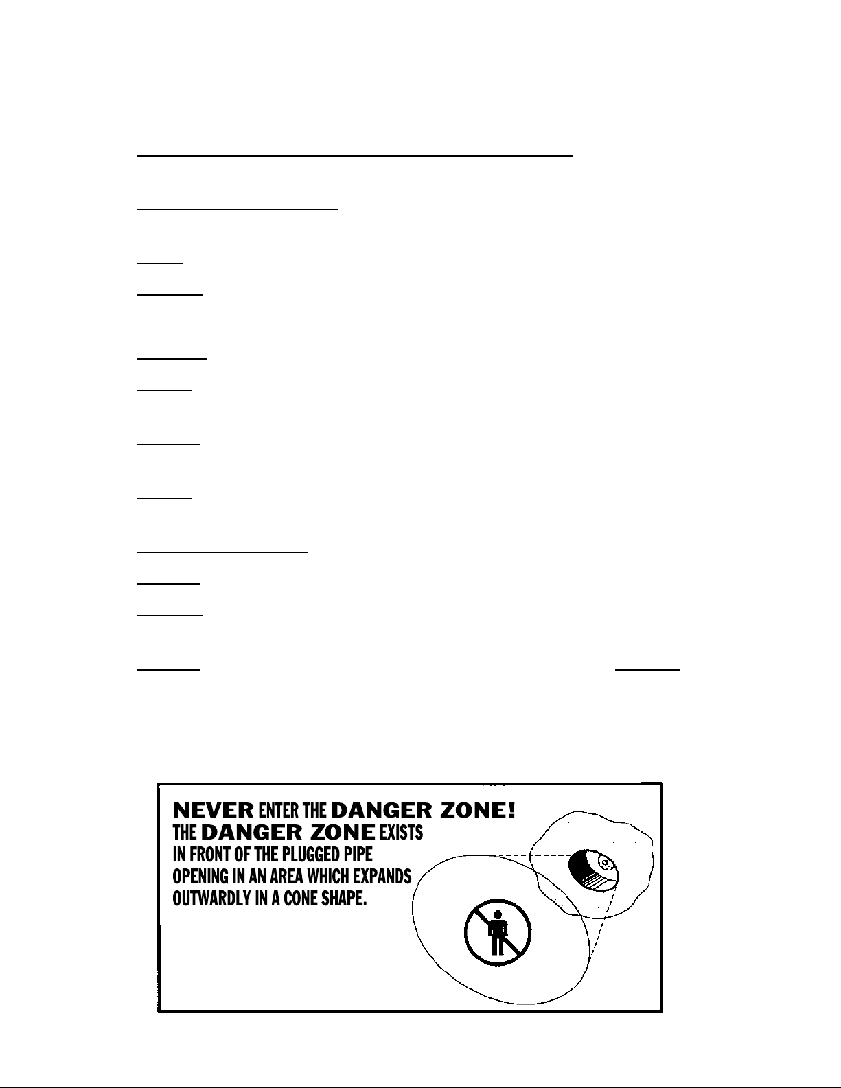
4. DO NOT ENTER DANGER ZONE WHEN PLUG IS IN USE.
5. MEASURE PIPE DIAMETER BEFORE SELECTING PLUG.
6. INSPECT PLUG FOR DAMAGE BEFORE AND AFTER USE.
7. NEVER USE A PLUG IN A PIPE SIZE DIFFERENT FROM RECOMMENDED
USAGE RANGE (REFER TO THIS SAFETY INSTRUCTION MANUAL).
8. ALWAYS ATTACH AN INFLATION EXTENSION HOSE SO PLUG CAN BE
INFLATED AND DEFLATED FROM OUTSIDE THE DANGER ZONE.
9. NEVER REMOVE THE INFLATION HOSE UNTIL ALL BACK PRESSURE IS
RELEASED AND THE PLUG IS DEFLATED.
10. MUST INFLATE PLUG TO THE PRESSURE SHOWN ON PLUG.
11. ALWAYS USE PROPERLY CALIBRATED PRESSURE GAUGES.
12. DO NOT EXCEED RECOMMENDED MAXIMUM ALLOWABLE
BACK PRESSURE (REFER TO THIS SAFETY INSTRUCTION MANUAL).
13. ALWAYS RELEASE BACK PRESSURE FROM THE PIPE FIRST, BEFORE
DEFLATING PLUG.
CALL 1-800-THE-PLUG OR 1-952-933-5501 IF ADDITIONAL CLARIFICATION IS
REQUIRED.
96C<:G
ODC:
CD

6
II. ALLGEMEINE SICHERHEITS UND BEDIENUNGSANLEITUNGEN
1. FALLS DER STÖPSEL AUS IRGENDEINEM GRUND VERSAGT, KANN DIES
ZUM TOD, ZU VERLETZUNGEN UND/ODER ZU SACHSCHADEN FÜHREN.
2. LESEN SIE DIESES SICHERHEITSHANDBUCH DURCH, UND MACHEN
SIE SICH MIT SEINEM INHALT VERTRAUT, BEVOR SIE DEN STÖPSEL
BENUTZEN.
3. ICHERHEITSBRILLE UND SCHUTZHELM MÜSSEN GETRAGEN WERDEN.
4. DIE GEFAHRENZONE DARF NICHT BETRETEN WERDEN, WENN DER
STÖPSEL BENUTZT WIRD.
5. MESSEN SIE DEN ROHRDURCHMESSER, BEVOR SIE DEN STÖPSEL WÄHLEN.
6. INSPIZIEREN SIE DEN STÖPSEL VOR UND NACH DEM GEBRAUCH AUF
BESCHÄDIGUNGEN.
7. BENUTZEN SIE AUF KEINEN FALL EINEN STÖPSEL IN EINER ROHRGRÖSSE,
DIE VOM EMPFOHLENEN EINSATZBEREICH ABWEICHT (WIR VERWEISEN
AUF DIESES SICHERHEITSHANDBUCH).
8. BEFESTIGEN SIE IMMER EINEN VERLÄNGERUNGSSCHLAUCH AM STÖPSEL,
UM VON AUSSERHALB DER GEFAHRENZONE DEN DRUCK ERHÖHEN BZW.
SENKEN ZU KÖNNEN.
9. ENTFERNEN SIE DEN VERLÄNGERUNGSSCHLAUCH AUF KEINEN FALL,
WENN NICHT SÄMTLICHER RÜCKSTAU FREIGESETZT UND DER STÖPSEL
ENTLEERT IST.
10. DER STÖPSEL MUSS AUF DEN AM STÖPSEL ANGEGEBENEN WERT
AUFGEBLASEN WERDEN.
11. BENUTZEN SIE IMMER ORDNUNGSGEMÄSS KALIBRIERTE MESSGERÄTE.
12. ÜBERSCHREITEN SIE NICHT DEN EMPFOHLENEN MAXIMAL GESTATTETEN
RÜCKSTAU (WIR VERWEISEN AUF DIESES SICHERHEITSHANDBUCH).
13. SETZEN SIE IMMER ZUERST DEN RÜCKSTAU AUS DEM ROHR FREI, BEVOR
SIE DEN STÖPSEL ENTLEEREN.
9>:<:;6=G:CODC:96G;6J;@:>C:C;6AA
7:IG:I:CL:G9:C:>C:<:;6=G:CODC:
:M>HI>:GIKDG9:GK:GHIyEH:AI:C
GD=Gy;;CJC<>C:>C:B7:G:>8=!
9:GH>8=@:<:A;yGB><C68=
6JHH:C:GL:>I:GI#
<:;6=G:C"
ODC:
C:>C

7
III. SÉCURITÉ GÉNÉRALES ET INSTRUCTIONS D’UTILISATION
1. DES BLESSURES PHYSIQUES OU MORTELLES ET DOMMAGES À LA
PROPRIÉTÉ PEUVENT ÊTRE CAUSES SI LE BOUCHON FAIT DÉFAUT POUR
TOUTE RAISON.
2. LIRE ET COMPRENDRE CE MANUEL D’INSTRUCTION SUR LA SÉCURITÉ
AVANT L’UTILISATION DU BOUCHON.
3. TOUJOURS PORTOR DES LUNETTES DE SÉCURITÉET UN CASQUE
PROTECTEUR.
4. NE PAS PÉNÉTRER DANS LA ZONE DE DANGER LORSQUE LE BOUCHON EST
EN USAGE.
5. MESURER LE DIAMÈTRE DU TUYAU AVANT DE CHOISIR LE BOUCHON.
6. VÉRIFIER SI LE BOUCHON N’EST PAS ENDOMMAGÉ aVANT ET APRÈS
L’UTILISATION
7. NE JAMAIS UTILISER UN BOUCHON POUR UN TUYAU DE GROSSEUR
DIFFÉRENTE DU CHOIX RECOMMANDÉ (SE RÉFÉRER AU MANUEL
D’INSTRUCTION SUR LA SÉCURITÉ).
8. TOUJOURS FIXER UN BOYAU DE RALLONGE DE GONFLEMENT DE FAÇON À
CE QUE LE BOUCHON PUISSE ÊTRE GONFLÉ ET DÉGONFLÉ À L’EXTÉRIEUR
DE LA ZONE DE DANGER.
9. NE JAMAIS RETIRER BOYAU DE GONFLEMENT TANT QUE TOUTE LA
CONTRE-PRESSION NE SERA PAS DÉGAGÉE ET QUE LE BOUCHON NE SERA
PAS DÉGONFLÉ.
10. GONFLER LE BOUCHON SELON LA PRESSION INDIQUÉE SUR CELUI-CI.
11. TOUJOURS UTILISER DE FAÇON APPROPRIÉE LES MANOMÉ CALIBRÉS.
12. NE PAS DÉPASSER LA CONTRE-PRESSION MAXIMALE PERMISE ET
RECOMMANDÉE (SE RÉFÉR AU MANUEL D’INSTRUCTION SUR LA SÉCURITE).
13. TOUJOURS DÉGAGER LA CONTRE-PRESSION DU TUYAU EN PREMIER, AVANT
DE DÉGONFLER LE BOUCHON.
C:?6B6>HEwCwIG:G96CHA6ODC:B9:96C<:G
A6ODC:9:96C<:GH:IGDJK:9:K6CI
A¼DJK:GIJG:9JIJN6JEDJGKJ9J
7DJ8=DC:IH¼wI:C9:C;DGB:9:
8ÕC:!K:GHA¼:MIwG>:JG# 96C<:G
ODC:
ODC:9:
96C<:G
CDC

8
IV. ISTRUZIONI GENERALI SULLA SICUREZZA E L’USO
1. DECESSO, LESIONI ALLE PERSONE E/O DANNI ALLE COSE POSSONO
VERIFICARSI SE, PER UN MOTIVO QUALSIASI, IL TAPPO PNEUMATICO
NON FUNZIONASSE CORRETTAMENTE.
2. LEGGERE E COMPRENDERE A FONDO IL PRESENTE MANUALE DI
ISTRUZIONI SULLA SICUREZZA PRIMA DI USARE IL TAPPO PNEUMATICO.
3. È OBBLIGATORIO INDOSSARE OCCHIALI DI PROTEZIONE ED ELMETTO.
4. NON INTRODURSI NELLA ZONA DI PERICOLO MENTRE IL TAPPO
PNEUMATICO È IN USO.
5. MISURARE IL DIAMETRO DELLA TUBATURA PRIMA DI SELEZIONARE IL
TAPPO PNEUMATICO ADATTO.
6. ESAMINARE IL TAPPO PNEUMATICO PRIMA E DOPO L’USO PER RILEVARE
GLI EVENTUALI DANNI DA ESSO SUBITI.
7. NON USARE MAI UN TAPPO PNEUMATICO SU UNA TUBATURA DI
DIMENSIONI NON ELENCATE TRA QUELLE CONSIGLIATE (CONSULTARE IL
PRESENTE MANUALE DI ISTRUZIONI SULLA SICUREZZA).
8. COLLEGARE SEMPRE UN TUBO DI GONFIAMENTO DI PROLUNGA
IN MODO CHE IL TAPPO PNEUMATICO POSSA ESSERE GONFIATO E
SGONFIATO DALL’ESTERNO DELLA ZONA DI PERICOLO.
9. NON RIMUOVERE MAI IL TUBO DI GONFIAMENTO PRIMA DI AVER
ELIMINATO TUTTA LA CONTROPRESSIONE E DI AVER SGONFIATO
COMPLETAMENTE IL TAPPO PNEUMATICO.
10. È NECESSARIO GONFIARE IL TAPPO PNEUMATICO ALLA PRESSIONE
MOSTRATA SUL TAPPO STESSO.
11. UTILIZZARE SEMPRE MANOMETRI CORRETTAMENTE CALIBRATI.
12. NON ECCEDERE LA CONTROPRESSIONE MASSIMA CONSENTITA
(CONSULTARE IL PRESENTE MANUALE DI ISTRUZIONI SULLA
SICUREZZA).
13. RILASCIARE SEMPRE LA CONTROPRESSIONE DALLA TUBATURA PER
PRIMA, PRIMA DI SGONFIARE IL TAPPO PNEUMATICO.
CDC>CIGD9JGH>B6>C:AA6ODC69>E:G>8DAD
A6ODC69>E:G>8DADÏJC¼6G:68DC>86
8=:E6GI:96AA¼6E:GIJG69:AA6
IJ76IJG69DI6I69>I6EED
EC:JB6I>8D!:H>:HI:C9:
K:GHDA¼:HI:GCD#
ODC6
9>E:G>8DAD
CD

9
V. INSTRUCCIONES DE SEGURIDAD GENERAL Y USO
1. SI EL TAPON FALLA POR CUALQUIER RAZON PUEDE PROVOCAR
MUERTE, LESIONES CORPORALES Y/O DAÑOS A LA PROPIEDAD.
2. ANTES DE USAR EL TAPON LEA Y ENTIENDA ESTA MANUAL DE
INSTRUCCIONES DE SEGURIDAD.
3. DEBE USAR GAFAS DE SEGURIDAD Y CASCO DURO.
4. NO ENTRE EN LA ZONA DE PELIGRO CUANDO ESTE EN USO EL TAPON.
5. MIDA EL DIAMETRO DE LA TUBERIA ANTES DE SELECCIONAR EL TAPON.
6. INSPECCIONE SI HAY DAÑOS EN EL TAPON ANTES Y DESPUES DE
USARLO.
7. NUNCA USE UN TAPON EN UN TAMAÑO DE TUBERIA DIFERENTE
DEL MARGEN DE USO RECOMENDADO (CONSULTE ESTE MANUAL DE
INSTRUCCIONES DE SEGURIDAD).
8. SIEMPRE INSTALE UNA MANGUERA DE EXTENSION DE INFLACION DE
MANERA QUE EL TAPON PUEDA INFLARSE Y DESINFLARSE DESDE FUERA
DE LA ZONA DE PELIGRO.
9. NUNCA RETIRE LA MANGUERA DE INFLACION HASTA QUE SE LIBERE
TODA LA PRESION ACUMULADA Y EL TAPON ESTE DESINFLADO.
10. DEBE INFLAR EL TAPON A LA PRESION ILUSTRADA EN EL TAPON.
11. SIEMPRE USE MEDIDORES DE PRESION CALIBRADOS EN FORMA
CORRECTA.
12. NO SOBREPASE LA PRESION ACUMULADA PERMITIDA MAXIMA
RECOMENDADA (CONSULTE ESTE MANUAL DE INSTRUCCIONES DE
SEGURIDAD).
13. SIEMPRE LIBERE LA PRESION ACUMULADA DESDE LA TUBERIA PRIMERO,
ANTES DE DESINFLAR EL TAPON.
«CJC86:CIG::CA6ODC69:E:A><GD
:M>HI:JC6ODC69:E:A><GD:CA6E6GI:
9:A6CI:G69:A66E:GIJG69:A6
IJ7:G>6I6E696:CJC6G:6FJ:H:
:ME6C96=68>66;J:G6:C;DGB6
9:8DCD#
9:E:A><GD
ODC6
«CD

10
VI.

11
1. INTRODUCTION.
CAREFULLY READ, UNDERSTAND AND FOLLOW THE USAGE
INSTRUCTIONS OUTLINED IN THIS BOOKLET. The safety
recommendations, principles and guidelines outlined in this manual apply
to the use of all Cherne pneumatic pipe plugs. All Cherne products are
designed, engineered and inspected with safety in mind. Cherne cannot
control or predict the unlimited work place variables that can affect safety
and usage conditions. Therefore safety must be your responsibility too!
THINK AND PRACTICE SAFETY WHENEVER YOU USE A PIPE PLUG!
THANK YOU FOR PURCHASING AND USING CHERNE PNEUMATIC
PLUGS AND ACCESSORIES. The instructions and warnings in this
manual are provided to assist you, our customer, to receive maximum
benet from the safe use of our products. This manual may be freely copied
and distributed. Additional copies are available, at no charge, upon request.
If you need additional copies or have questions call Cherne toll free at
1-800-843-7584 or fax toll free at 1-800-843-7585. Emergency assistance
and emergency product shipment (surcharge applies to emergency after
hours shipments) is also available through the toll free 1-800-843-7584
phone number 24 hours per day.
CHERNE WISHES TO EXPRESS THANKS TO THOSE WHO HAVE
CONTRIBUTED TO THIS MANUAL. If you have suggestions on how
we can improve this manual or have additional data you think would be
pertinent that should be added, please call Cherne toll free at 1-800-843-
7584.
CHERNE PROVIDES TRAINING ASSISTANCE. If your organization (eg.
Union School, Tech School, Sewage District, Trade Organization, etc.)
provides training on a topic such as testing, product safety or a related
topic, please contact us for help. Cherne will provide free training materials
(eg. copies of testing standards, product catalogs, Safety Instruction
Manuals, specication sheets, safety tags, etc.) to assist your presentation.
Upon request, a company representative may assist in the presentation.
Call Cherne toll free at 1-800-843-7584 to further discuss this assistance.
WARNING AN INHERENT DANGER EXISTS WITH ALL
INFLATABLE PRODUCTS, ANY PRESSURIZED PIPELINE OR OTHER
PRESSURE CONTAINMENT SYSTEMS! Every pneumatic plug, like tires, will
eventually wear out and fail from continued use. Abuse and misuse will greatly
accelerate this failure. Always protect against the eventuality of plug failure to
prevent injury and property damage. If any conditions exist with equipment
that may jeopardize the safety of yourself or others or if you are unsure about
proper use, DO NOT USE THE EQUIPMENT. If you have any questions or
think any unusual conditions exist that are not described in this booklet, consult
your supervisor or safety director before proceeding. FAILURE TO COMPLY
WITH THESE SAFETY INSTRUCTIONS OR THOSE OF OSHAAND YOUR
FEDERAL, STATE OR LOCAL GOVERNMENTS, MAY RESULT IN DEATH,
SERIOUS BODILY INJURY AND/OR PROPERTY DAMAGE!

12
2. DETERMINE THE AMOUNT OF BACK PRESSURE THE PLUG
MUST WITHSTAND FOR THE JOB OR APPLICATION.
DETERMINE THE MAXIMUM BACK PRESSURE (the differential uid
pressure, either air or liquid, restrained by the plug) the plug must withstand
before selecting a plug.
WATER BACK PRESSURE (hydrostatic back pressure) is measured in either
feet-of-head (uid height above centerline of the plug) or PSIG (Pounds Per
Square Inch Gauge). AIR BACK PRESSURE (pneumatic back pressure) is
measured in PSIG (Pounds Per Square Inch Gauge). See Conversion Table on
page 15.
MAXIMUM ALLOWABLE BACK PRESSURE for each Cherne pneumatic
pipeline plug is clearly outlined in the data section of this manual, Cherne
catalogs and product specication sheets. Maximum back pressure ratings
listed are for plugs installed in clean, dry pipe of nominal size. Usage of plugs
in pipeline that varies from these conditions may reduce maximum allowable
back pressure.
MAXIMUM BACK PRESSURE RATING - AIR VERSUS WATER. Pipeline
plugs will normally hold (withstand) nearly equal back pressure for water
pressure (hydrostatic pressure) or air pressure (pneumatic pressure).
However, extra caution must be given when using a plug in an air pressure
application. Air pressure is more likely to cause a pipeline plug to dislodge at
high velocity.
EQUAL BACK PRESSURE MAY BE RESTRAINED FROM EITHER
THE FRONT OR THE BACK OF THE PLUG. VACUUM IS NEGATIVE
PRESSURE. A plug’s maximum allowable back pressure rating is
independent of the direction the back pressure is applied. This also
includes pressure caused by a vacuum which is equivalent to a negative
pressure in the direction of the vacuum. Each 1” Hg (Mercury) of vacuum is
approximately -0.5 PSIG of pressure. If pressure exists on one side of the
plug and vacuum on the other side, the forces must be added to calculate
total back pressure. A vacuum may be created by pumping water from either
side of the plug and not venting the evacuated area.
NEVER ENTER THE DANGER ZONE. The approximate Danger Zone exists
in front of the plugged pipe opening in an area which expands outwardly in
a cone shape. The Danger Zone includes the entire area where a pipeline
plug, any portions (fragments) thereof and/or any media (back pressure)
restrained by the pipeline plug may be ejected from the pipeline should the
plug rupture or dislodge for any reason. Although the Danger Zone described
applies to normal usage conditions, the foreseeable Danger Zone increases
as ination pressure is increased, as back pressure builds and by possible
ricochet effects from pipes, walls or other objects in the Danger Zone. The
area of foreseeable Danger Zone may be reduced by the use of a backup
system (refer to Section 11 of this manual).
DANGER
ZONE
WATER
WATER BACK PRESSURE
WATER COLUMN IN FEET
ABOVE PIPE CENTERLINE
DANGER
ZONE
AIR BACK PRESSURE
PSIG
BACK
PRESSURE

13
DANGER NEVER ENTER INTO THE FORESEEABLE DANGER
ZONE WHEN A PNEUMATIC PLUG IS INFLATED EVEN IF NO BACK
PRESSURE EXISTS IN THE PIPE! IF YOU OR ANYONE ELSE IS IN
THE DANGER ZONE AND THE PLUG FAILS OR DISLODGES FOR ANY
REASON, FAILURE TO HEED THIS WARNING MAY RESULT IN DEATH,
SERIOUS BODILY INJURY AND/OR PROPERTY DAMAGE!
MONITOR BACK PRESSURE DURING PLUG USE. Monitor water back
pressure by attaching a calibrated pressure gauge or a vertical sight tube
to the bypass of a Muni-Ball® plug. A gauge must be located at pipe
centerline to accurately measure water pressure. Other applications may
allow direct measurement of the water column height restrained by the
plug. Air back pressure can be monitored by attachment of a calibrated
pressure gauge to the plug bypass port using an extention hose. This
allows accurate back pressure readings from a remote location outside of
the Danger Zone.
DANGER
ZONE
DANGER
ZONE
TO
SEWER
C
L
PIPE
WATER
WATER
WATER
DANGER
ZONE
DANGER
ZONE
DANGER
ZONE
SOME
APPLICATIONS
ALLOW DIRECT
MEASUREMENT
OF WATER
HEIGHT
ATTACH A CLEAR
SIGHT TUBE TO
MUNI-BALL® PLUG
BYPASS TUBE
ATTACH CALIBRATED
PRESSURE GAUGE TO
MUNI-BALL® PLUG
BYPASS TUBE
GAUGE PORT READING MUST BE
CORRECTED FOR HEIGHT ABOVE
PLUG CENTERLINE
A CALIBRATED PRESSURE
GAUGE CAN REMOTELY
PROVIDE ACCURATE AIR
BACK PRESSURE
MEASUREMENT
AIR
WATER HEIGHT

14
HOW TO CALCULATE PIPELINE FORCES AND PRESSURES.
A. MEASURE THE INSIDE DIAMETER OF THE PIPELINE IN INCHES.
B. DETERMINE THE MAXIMUM BACK PRESSURE. Air pressure is
measured in PSIG (Pounds Per Square Inch Gauge). Water pressure is
calculated by determining the height of water column in feet above the center
line of the pipe. Water height is multiplied by (0.43) to yield water pressure in
PSIG. A FEET-OF-WATER-HEAD TO PSIG conversion table is also provided
(see Table 1, next page).
C. CALCULATE THE PIPE AREA IN SQUARE INCHES. Area of a circle
(square inches) = [Diameter (in inches) x Diameter (in inches) x 3.1416 (pi)]
/ 4.
D. CALCULATE THE FORCE THE PLUG MUST WITHSTAND. FORCE =
PIPE AREA (in square inches) x PRESSURE (PSIG).
EXAMPLE: A plug must hold a (10) foot column of water above the
centerline of a 60” diameter pipe.
PIPE AREA = [60” (dia.) x 60” (dia.) x 3.1416 (pi)]/ 4 = 2,827 square inches.
PRESSURE = 10 Feet of Water x 0.43 PSIG/Foot = 4.3 PSIG
PIPE AREA (2,827 square inches) x PRESSURE (4.3 PSIG) = FORCE =
12,157 pounds.
WATER WILL ACCUMULATE BEHIND ANY PLUG BLOCKING A
FLOWING LINE. The ow will gradually increase the water column height
behind the plug. Prior to installing a plug, the user must determine the
maximum water height that may accumulate during plug use.
DANGER ZONE
WATER
BRACING
DETERMINE MAXIMUM
WATER HEIGHT THAT MAY
ACCUMULATE ABOVE PIPE CENTER
INFLATION
PRESSURE
GAUGE
READ BACK
PORT

15
WARNING NEVER EXCEED THE PLUG’S BACK PRESSURE
RATING! Maximum recommended back pressure ratings listed are for plugs
installed in clean, dry pipe. Other pipe conditions, such as a pipe with debris
or foreign substances on its surface, may signicantly reduce back pressure
holding capabilities. Harmful foreign substances may include grease, mold,
algae, sand and/or any other material that prevents solid contact between
the plug and the pipe wall. Pipe made from material having a low coefcient
of friction, such as polyethylene, or new pipe having traces of release agent
used as part of the manufacturing process may also reduce the back pressure
holding capabilities. Corrugated piping will also reduce back pressure
holding capabilities (by 50%–see page 18). IF SUCH CONDITIONS EXIST,
IMMEDIATELY NOTIFY YOUR SUPERVISOR OR SAFETY DIRECTOR
AND TAKE APPROPRIATE CORRECTIVE ACTION SUCH AS CLEANING
BEFORE PROCEEDING! FAILURE TO HEED THIS WARNING MAY CAUSE
PLUG DISLODGEMENT WHICH MAY RESULT IN DEATH, SERIOUS
BODILY INJURY AND/OR PROPERTY DAMAGE!
WARNING TREMENDOUS FORCES MAY BE RESTRAINED
INSIDE OF AND BY PIPELINE PLUGS WHEN THE PLUGS ARE INFLATED
AND USED! Total force exerted on a pipeline plug is directly proportional
to both the pressure and the pipeline area (refer to formula and example,
page 14). ANY BARRIER OR BLOCKING DEVICE USED TO RESTRAIN
THE PLUG IN A PIPELINE MUST BE PROPERLY DESIGNED AND
CONSTRUCTED TO SAFELY WITHSTAND THE HIGH FORCES INVOLVED!
FAILURE TO USE PROPER BRACING MAY RESULT IN DEATH, SERIOUS
BODILY INJURY AND/OR PROPERTY DAMAGE (SEE PAGE 32)!
CONVERSION TABLE
FEET-OF-WATER-HEAD TO PSIG
(Pounds Per Square Inch Gauge)
FT.-OF-
HEAD PSIG FT.-OF-
HEAD PSIG FT.-OF-
HEAD PSIG FT.-OF-
HEAD PSIG
1 = 0.43 16 = 6.93 31 = 13.42 46 = 19.92
2 = 0.87 17 = 7.36 32 = 13.86 47 = 20.35
3 = 1.30 18 = 7.79 33 = 14.29 48 = 20.78
4 = 1.73 19 = 8.23 34 = 14.72 49 = 21.22
5 = 2.16 20 = 8.66 35 = 15.15 50 = 21.65
6 = 2.60 21 = 9.09 36 = 15.59 51 = 22.08
7 = 3.03 22 = 9.53 37 = 16.02 52 = 22.52
8 = 3.46 23 = 9.96 38 = 16.45 53 = 22.95
9 = 3.90 24 = 10.39 39 = 16.89 54 = 23.38
10 = 4.33 25 = 10.82 40 = 17.32 55 = 23.82
11 = 4.73 26 = 11.26 41 = 17.75 56 = 24.25
12 = 5.20 27 = 11.69 42 = 18.19 57 = 24.68
13 = 5.63 28 = 12.12 43 = 18.62 58 = 25.11
14 = 6.06 29 = 12.56 44 = 19.05 59 = 25.55
15 = 6.49 30 = 12.99 45 = 19.49 60 = 25.96
TABLE 1

16
WARNING MOST STANDARD CHERNE PNEUMATIC PLUGS
ARE DESIGNED TO HOLD AIR OR WATER BACK PRESSURE ONLY
AND MUST ONLY BE USED WITHIN THE DESIGNATED TEMPERATURE
RANGE! Use with other media or at temperatures outside of designated
range may cause the plug to fail. PLUG FAILURE MAY RESULT IN
DEATH, SERIOUS BODILY INJURY AND/OR PROPERTY DAMAGE!
3. DETERMINE THE USAGE TEMPERATURE AND THE
MEDIA THE PLUG MUST WITHHOLD.
TEMPERATURE RATING. Most standard Cherne natural rubber pneumatic
plugs are designed for use at temperatures from 0 to +125 DEGREES F.
(-18 to +52 DEGREES C.). Using a plug at a temperature below this
minimum may cause the plug to stiffen, resulting in incomplete pipe
contact, and the plug may dislodge when back pressure is applied. Usage
at temperatures above this maximum may damage the plug body and the
plug may rupture during ination and/or use. If the application requires
temperatures outside of these limits, call Cherne toll free at 1-800-843-
7584 for recommendations.
USE OF PLUGS WITH CHEMICALS. If a plug is to be used in
chemical environments, call Cherne toll free at 1-800-843-7584 for
recommendations.

17
4. MEASURE THE PIPE AND SELECT THE PROPER PLUG
AND RELATED EQUIPMENT.
EVERY PIPELINE PLUG HAS A MINIMUM AND MAXIMUM SEALING
SIZE RANGE AND A MAXIMUM ALLOWABLE BACK PRESSURE
RATING. The allowable sealing size usage range and maximum allowable
back pressure are outlined in the data section of this manual, Cherne
catalogs and specication sheets. Nominal plug size is clearly marked on the
product. However, certain types and classes of pipe may have actual inside
diameters that vary considerably from nominal diameters and may, therefore,
be larger or smaller than the plug’s sealing size usage range.
MEASURE THE INSIDE DIAMETER OF THE PIPE. VERIFY THE
DIAMETER IS WITHIN THE PLUG’S RECOMMENDED SEALING SIZE
USAGE RANGE. NEVER EXCEED MAXIMUM ALLOWABLE BACK
PRESSURE. VERIFY THAT THE PROJECTED BACK PRESSURE IS
WITHIN THE PLUG’S MAXIMUM ALLOWABLE BACK PRESSURE
RATING.
PNEUMATIC PLUGS ARE ONLY RECOMMENDED FOR TEMPORARY
SEALING. Pneumatic pipeline plugs are to be used only for the few hours
that are necessary to perform a task! If a pneumatic plug must be used
for extended periods, the ination pressure must be CHECKED AND
ADJUSTED (IF NECESSARY) EVERY FOUR HOURS. Over time, a small
volume of air will leak through the elastomeric (rubber) body of every
pneumatic plug. The lost air must be replaced or under-ination may result
allowing the plug and any media restrained to dislodge from the pipe. A
regulated pressure source may be permanently attached to the plug’s
ination inlet port as an alternative to periodically checking and adjusting the
ination pressure. Consult with a registered professional engineer for the
construction and maintenance of such a pressure regulated ination source
(refer to description of panel and warnings in Section 12 of this manual if you
are constructing a regulated pressure source). For long term or permanent
usage, a Cherne mechanical plug is recommended. Call Cherne toll free at
1-800-843-7584 for recommendations.
PNEUMATIC PLUGS VERSUS MECHANICAL PLUGS. Pneumatic plugs
have many advantages over mechanical plugs. They normally have a much
wider sealing range than mechanical plugs. Some pneumatic plugs may
even be used in multiple sizes of pipes. Pneumatic plugs easily seal minor
imperfections in pipe and can seal non-circular pipe shapes. Pneumatic
plugs normally have a long contact area with the pipe which minimizes
leakage in rough or porous pipe. They also can be inated and deated from
a remote location out of the Danger Zone and can be positioned in many
areas that are not accessible to mechanical plug use. Mechanical plugs
have the advantage of not relying on ination pressure to provide proper
sealing and are a better choice for long term or permanent usage. When the
plugging application requires a minimum sealing length, a narrow mechanical
plug may be the only viable option, as proper installation of a long pneumatic
plug may not be possible. Mechanical plugs generally have a much shorter
sealing length requirement.

18
CORRUGATED PIPE. Pneumatic plugs may be used in corrugated
pipe. However, the plug will not fully ll the pipe corrugations, resulting in
reduced contact area. Maximum allowable back pressure, therefore, must
be reduced by 50% (eg. a plug normally rated for 30 feet of back pressure
must be derated to 15 feet). Minor media leakage may still result along the
longitudinal pipe construction seams. When a plug is used in spiral type
corrugated pipe, a section of corrugations must be lled with a material
such as cement grout to prevent major leakage around the spirals.
PLUGS MAY NOT TOTALLY SEAL SOME TYPES OF PIPE. When pipes
have rough or very uneven surfaces, such as brick lined pipe, the plug
may allow minor leakage of the restrained media. Some concrete pipe is
very porous and media may leak past the plug through the pipe itself. The
surface of the pipe may need to be coated with sealant to prevent such
leakage. Other concrete pipe has a cast in place plastic liner, and leakage
may occur under the liner. The edges of the plastic liner may require
caulking to provide a leak free seal. Other pipe with sharp (90º) corners,
longitudinal seams or defects may provide a leakage path past the plug.
DO NOT attempt to prevent the leakage described above by over-ination
of the plug. Over-ination will not provide a better seal and the plug may
rupture catastrophically and dislodge at high velocity. Such leakage may
only be minimized or eliminated by mechanically blocking the leakage path
with material such as caulk or cement grout.
OTHER PIPE SHAPES. Pneumatic plugs may also be used to block pipes
that have non-circular cross sections (eg. elliptical, arch or rectangular).
Measure the pipe and call Cherne toll free at 1-800-843-7584 for
recommendations for your application. A standard plug or fabrication of a
custom sized product may be recommended. Cherne can quickly determine
what plug will best meet your performance requirements.
MEASURE INSIDE PIPE
DIAMETER AND
SELECT THE
PROPER
PLUG
SIZE
PNEUMATIC PLUGS
MAY BE USED
TO BLOCK OTHER
PIPE SHAPES

19
DETERMINE THE TYPE OF PNEUMATIC PLUG REQUIRED. Cherne offers a
wide variety of plug types including:
a. Blocking type pneumatic plugs (Test-Ball® plugs).
b. Plugs for sealing wyes (Long Test-Ball® plugs and MS2® Long Test-Ball®
plugs).
c. Plugs for sealing test tees (Clean-Seal® plugs).
d. Plugs with a bypass through the plug (Muni-Ball® plugs).
e. Plugs with maximum bypass size for gravity ow bypass applications (Big-
Mouth® Flow Through plugs).
f. Plugs for remote placement (REMO® plugs).
g. Plugs (large diameter) capable of tting through small diameter openings
(Urethane Test-Ball® and Muni-Ball® Plugs).
h. Plugs for air testing sewer lines (AIR-LOC® plugs).
NOTE: Refer to Section 13 of this manual to determine what method will be
used to remove back pressure before plug deation. Then select the necessary
plug(s) and related equipment. Many sizes of plugs are available in several
product congurations optimized for specic applications. Consult your catalog,
Cherne dealer or call Cherne toll free at 1-800-843-7584 for recommendations.
WARNING NEVER ATTEMPT TO USE A PLUG PRODUCT IN
A PIPE SMALLER OR LARGER THAN THE RECOMMENDED SEALING
SIZE USAGE RANGE! Media leakage, product failure and/or plug
dislodgement may result. PLUG FAILURE OR DISLODGEMENT MAY
RESULT IN DEATH, SERIOUS BODILY INJURY AND/OR PROPERTY
DAMAGE!
CAUTION CHECK THE PRESSURE RATING OF THE PIPE TO
BE SEALED. The pipe’s internal pressure rating must exceed the ination
pressure for the pneumatic plug selected for use. A plug body may exert a
force on the pipe wall nearly equal to the ination pressure. Damage to the
pipe, such as breakage, may occur if the pipe has a lower pressure rating
than the plug’s ination pressure. Special caution should be used with
brittle pipe such as clay or non-reinforced concrete if a plug is used before
the pipe is properly backlled.

20
5. CLEAN PLUG AND RELATED EQUIPMENT BEFORE
EVERY USE AND INSPECT FOR DAMAGE.
CLEAN PLUG. Pneumatic plugs may be cleaned with a solution of mild
detergent and water. After cleaning, ush the plug with clean water and allow it to
air dry thoroughly before use.
INSPECT PLUG AND RELATED EQUIPMENT. Carefully inspect the pneumatic
plug and all related equipment for indications of wear or deterioration prior
to each use. The plug may be inated slightly (1 PSIG - refer to warning on
following page) to aid in the inspection process. After ination, apply a solution of
water and detergent to the equipment or submerge the product completely under
water as an aid in locating leaks. Bubbles will form at the site of any air loss.
Look very carefully for evidence that any material of the plug assembly and
related equipment has been damaged, weakened or is missing. The inspection
should include but not be limited to looking for:
a. Cuts.
b. Abrasions.
c. Punctures.
d. Presence of a proper ination source (refer to Section 12 of this manual).
e. Bulges.
f. Cracked castings.
g. Softening of elastomer (rubber).
h. Cracks in elastomer (rubber).
i. Corrosion.
j. Loose, corroded or damaged ttings.
k. Leaks from or damage to inator assembly.
l. Leaks from or damage to ination extension hoses.
m. Dirt or debris lodged in the inator valve which may cause a slow ination leak.
n. Protective inator cap in place.
o. An orange warning tag attached to the plug. Replacement tags are available at no charge,
upon request. Call Cherne toll free at 1-800-843-7584 and ask for a Warning Tag.
p. A copy of this Safety Instruction Manual to accompany plug for user reference. NOTE:
Call Cherne toll free at 1-800-843-7584 to request the most current revision of the Safety
Instruction Manual. Additional application information, instructions and warnings are
periodically added as Cherne becomes aware of such information. Additional Manual
copies are available from Cherne, at no charge, upon request.
q. Loose or damaged banding clamps.
r. Eye bolts, chain and ring or tether attachment in location.
s. Inator valve core in place, properly tightened and leak free in the ination tting.
t. Presence of a properly calibrated ination pressure gauge to accurately determine ination
pressure (refer to Section 12 of this manual).
IF ANY EVIDENCE OF DAMAGE, DETERIORATION, MISSING
COMPONENTS, WARNING TAG/MANUAL LOSS, OR EXCESS
WEAR IS OBSERVED, CONSULT YOUR LOCAL CHERNE
DEALER OR REPRESENTATIVE AND MAKE ARRANGEMENTS
TO RETURN THE PRODUCT FOR INSPECTION OR DESTROY
This manual suits for next models
5
Table of contents
Other CHERNE Industrial Equipment manuals
Popular Industrial Equipment manuals by other brands

Universal
Universal MC-10NI Series owner's manual

Pilz
Pilz PSEN sl-0.5p 1.1 operating manual

ATD Tools
ATD Tools Atd-7227 Operating instructions & parts manual

TGW
TGW Natrix Installation, operation & maintenance manual

Finn
Finn HydroSeeder T30 Parts and Operator's Manual

Nexen
Nexen AIR CHAMP FMCBE-625 user manual