CHERRY AUDIO VM901 User manual

Voltage Modular: Cherry Audio MRB modules
This content was taken from the product pages on 28 October 2021.

Voltage Modular: Cherry Audio / MRB Modules User Manual
Page 2
Table of Contents
1 CP3 Console Panel Mixer.................................................................................................. 4
2 VM901 Voltage Controlled Oscillator............................................................................... 6
3 VM901ABBB Voltage Controlled Oscillator...................................................................... 8
4 VM902 Amplifier ............................................................................................................ 10
5 VM903 Random Signal Generator.................................................................................. 11
6 VM904A/B/C Filters........................................................................................................ 12
7 VM905 Reverb................................................................................................................ 16
8 VM907A Fixed Filter Bank .............................................................................................. 17
9 VM911 Envelope Generator........................................................................................... 18
10 VM911-A Dual Trigger Delay .......................................................................................... 21
11 VM912 Envelope Follower ............................................................................................. 22
12 VM914 Fixed Filter Bank................................................................................................. 24
13 VM921ABBB Oscillator Bank .......................................................................................... 25
14 VM921 Voltage Controlled Oscillator............................................................................. 25
15 VM923 Filters/Noise....................................................................................................... 29
16 VM927 Multiple.............................................................................................................. 31
17 VM928 Sample Hold....................................................................................................... 32
18 VM958 Keyboard/VCO Interface.................................................................................... 34
19 VM960 Sequencer .......................................................................................................... 37
20 VM962 Sequential Switch............................................................................................... 40
21 VM984 Four-Channel Matrix Mixer................................................................................ 41
22 VM995 Attenuators........................................................................................................ 42
23 VM1630 Frequency Shifter............................................................................................. 43
24 VM2500 Blank Panel Module 1001 ................................................................................ 45
25 VM2500 Clocked Sequential Control Module 1027 ....................................................... 46
26 VM2500 Dual Envelope Generator Module 1003 .......................................................... 51
27 VM2500 Dual Envelope Generator Module 1033 .......................................................... 54
28 VM2500 Dual Four-Channel Mixer Module 1051 .......................................................... 57
29 VM2500 Dual Noise/Random Voltage Generator Module 1016 oscillators .................. 58
30 VM2500 Dual Oscillator Module 1023 ........................................................................... 59
31 VM2500 Dual Reverberator Module 1025 ..................................................................... 61
32 VM2500 Filtamp Module 1006....................................................................................... 63
33 VM2500 Mix-Sequencer Module 1050 .......................................................................... 65
34 VM2500 Modamp Module 1005 .................................................................................... 68
35 VM2500 Multimode Filter Resonator Module 1047 ...................................................... 70
36 VM2500 Oscillator Module 1004-P ................................................................................ 73
37 VM2500 Oscillator Module 1004-R ................................................................................ 75

Voltage Modular: Cherry Audio / MRB Modules User Manual
Page 3
38 VM2500 Oscillator Module 1004-T ................................................................................ 77
39 VM2500 Oscilloscope Module 1019............................................................................... 79
40 VM2500 Preset Voltage Module 1026 ........................................................................... 81
41 VM2500 Quad Envelope Generator Module 1046......................................................... 83
42 VM2500 Sample & Hold Module 1036........................................................................... 86
43 VM2500 Synthesizer Voice Module 1045 ...................................................................... 88
44 VM2500 Triple VCA Module 1042 .................................................................................. 93
Voltage Modular: Cherry Audio / MRB Modules User Manual
Page 4
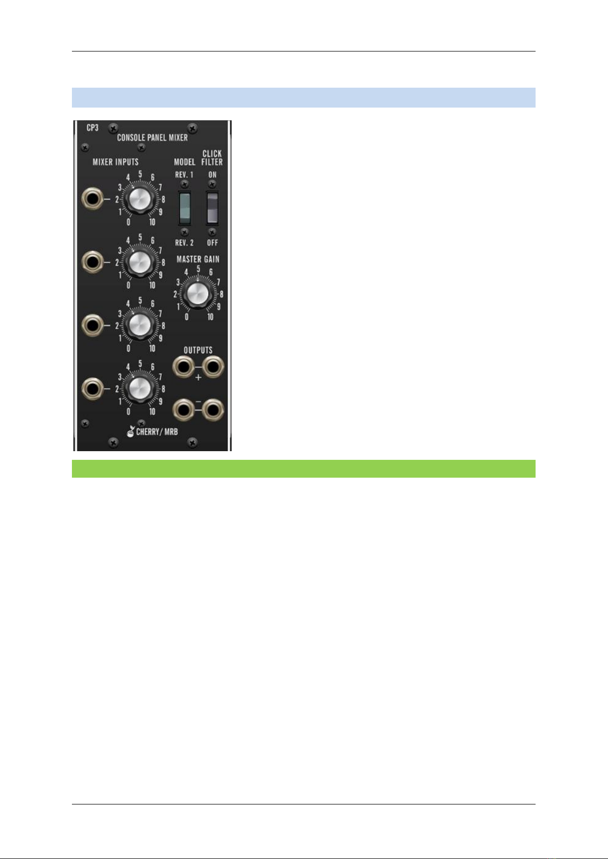
1CP3 Console Panel Mixer
The VM900 CP3 is a recreation of the classic Moog
"Console Panel Mixer." At high inputs levels, it had a
tendency to clip the tops and bottoms of waveforms for a
characteristic overdriven tone. We've also included a
switch that allows selection between the more overdriven
tone and the later, cleaner-sounding version.
Note that CP3 is DC-coupled and can be used to mix audio
or sub-audio CV signals.
1.1 Inputs, Outputs, and Controls
The four inputs are stacked vertically on the left side of the panel; we'll go over the
repeated controls just once.
Mixer Inputs jacks and level knobs- Plug inputs into the jacks and set volumes with the
knobs. Signals will tend to clip at higher input levels, particularly when the Model switch is
set to the Rev. 1 position.
Model- Selects the audio characteristics of the earlier or later production CP3 circuit. Rev. 1
has more of a tendency to clip waveforms, whereas Rev. 2 is less inclined to break up.
Click Filter- When engaged, this rounds of sharp waveform edges to reduce clicking - it's
intended for use with edgy control signals to reduce clicking when patched to something
such as a VCA CV. The Click Filter is generally not recommended for use with audio signals.
Master Gain- Sets overall output volume. While turning up the four input levels will increase
distortion (especially in rev1), Master Gain is pure output gain and has no effect on
distortion.

Voltage Modular: Cherry Audio / MRB Modules User Manual
Page 5
+/- Output jacks - Signal outputs for positive and inverted mixed signals. The (-) out, in
addition to being inverted from the (+) out, does not sound the same in Rev. 1 mode - the
distortion characteristics are very different between the two jacks. In fact, the outputs are
so different that there is quite a stereo image to be had between them. Rev. 2 mode is
purely clean and does not exhibit these quirks.

Voltage Modular: Cherry Audio / MRB Modules User Manual
Page 6
2VM901 Voltage Controlled Oscillator
The VM901 is a full-function oscillator
module. It can be used in the audio range,
or as a low-frequency modulation source.
2.1 Inputs, Outputs, and Controls
Fixed Voltage Control- Sets the range down five octaves or up six octaves.
Frequency Range- Sets the coarse frequency range to sub-audio or standard audio ranges in
standard organ footages. Use the Lo setting when using VM901 as low-frequency
modulation source.
Fine Tuning (0/1/2)- Allows continuously variable tuning down (0) or up (2) one octave.
Width Of Pulse Waveform- Sets the width or "duty-cycle" of the rectangular (aka, pulse)
wave. It has no effect on any other waveform. Its default setting of 50% produces a perfect
square wave, rich in odd-order harmonics. Moving the knob left or right narrows its width as
well as the thickness of sound until it almost disappears at its extremes.
Control Inputs- These are 1V/octave exponential inputs. They're used for pitch CV as well as
modulating the oscillator frequency. All three jacks are the same and their incoming
voltages are summed.
Sine/Saw/Triangular/Pulse volume knobs- These set the volume of each waveform for each
respective output jack in the bottom row.

Voltage Modular: Cherry Audio / MRB Modules User Manual
Page 7
Fixed Level Outputs- These are outputs for the sine, sawtooth, triangular, and pulse waves,
respectively. They not affected by the Sine/Saw/Triangular/Pulse knobs and are always at
full output level.
Sine/Saw/Triangular/Pulse adjustable outputs- These are outputs for the sine, sawtooth,
triangular, and pulse waves, respectively. Their output level is set by the Sine, Sawtooth,
Triangular, and Pulse volume knobs.

Voltage Modular: Cherry Audio / MRB Modules User Manual
Page 8
3VM901ABBB Voltage Controlled Oscillator
The VM901ABBB is an
oscillator bank that
replicates the unique
oscillator controller/slave
arrangement of classic
Moog synthesizers.
The concept is that the
Oscillator Controller
module sets the overall
coarse tuning as well as
rectangular wave pulse
width for the three slave
oscillators.
In the original hardware
modular systems, the
oscillator controller and
slaves were connected
internally.
Any number of slave oscillators could be used, but the "one+three" combo was common,
and we felt it represented a good compromise of utility and size. Though these have the
appearance of four individual single-width modules, VM901ABBB is a single quad-width
module. If for you need something physically narrower, use the VM901 oscillator module.
3.1 901-A Oscillator Controller
The oscillator driver is the "master control" center; all of its control settings will affect the
three slave oscillators. Changing its Frequency setting will equally offset all three slave
oscillators, for example.
3.1.1 Inputs, Outputs, and Controls
Fixed Voltage Control- Sets the range down five octaves or up six octaves.
Frequency Range- Sets the coarse frequency range to sub-audio or standard audio ranges in
standard organ footages. Use the Lo setting when using VM901 as low-frequency
modulation source.
Fine Tuning (0/1/2)- Allows continuously variable tuning down (0) or up (2) one octave.

Voltage Modular: Cherry Audio / MRB Modules User Manual
Page 9
Width Of Pulse Waveform- Sets the width or "duty-cycle" of the rectangular (aka, pulse)
wave. It has no effect on any other waveform. Its default setting of 50% produces a perfect
square wave, rich in odd-order harmonics. Moving the knob left or right narrows its width as
well as the thickness of sound until it almost disappears at its extremes.
Control Inputs jacks- These are 1V/octave exponential inputs. They're used for pitch CV as
well as modulating the oscillator frequency. All three jacks are the same; signals received
will be summed and are multed to all three slave oscillators.
3.2 901-B Slave Oscillators
As mentioned, 901-A oscillator driver settings equally affect all three slave oscillators.
Conversely, settings on individual 901-B slave oscillators are independent and have no affect
on the adjacent oscillators.
3.2.1 Inputs, Outputs, and Controls
Frequency Range- Sets the coarse frequency range to sub-audio or standard audio ranges in
standard organ footages. Use the Lo setting when using VM901 as low-frequency
modulation source.
Frequency Vernier- Allows continuously variable tuning down or up by about one octave
and a major third.
Sine/Saw/Triangular/Pulse output jacks- Outputs for the sawtooth, sine, pulse, and
triangular waves, respectively.

Voltage Modular: Cherry Audio / MRB Modules User Manual
Page 10
4VM902 Amplifier
The idea of a voltage-controlled amplifier (VCA) is that an audio or control
signal is patched to its input, and externally controlled voltage controlled
via the Control Inputs jacks. This is useful for turning audio or control
signals on or off, applying envelope volume curves to sounds, regulating
the amount of modulation signals applied to audio signals, and more.
A simple analogy would be to think of a water faucet, with the control
voltage affecting how much the faucet is opened.
4.1 Inputs, Outputs, and Controls
Linear (Lin.)/Exponential (Exp.)- Selects the "curve" of the amplifier's response as the input
CV rises from 0 to 5V. Lin. or linear response curve is equally proportional across the voltage
input range, whereas Exp. or exponential curve is closer to how the human ear perceives
volume. You'll likely want to use the Lin. setting for modulation or control voltage situations,
and use the Exp. setting when an envelope generator is used to control an audio signal with
the amplifier. Or just use whatever sounds best, we won't tell.
Fixed Control voltage- Adds up to 5V of gain. This works in addition to incoming and Control
Inputs jack voltages. It's useful for manually "opening" the amplifier for drones.
Control Inputs jacks- Control signal inputs are patched in here. These have no attenuators
and are "wide open" all the time - typically these would be used to patch an envelope
generator. All three jacks are the same, and when more than one is used, incoming voltages
are summed.
Signal Inputs jacks- Use this jack to patch in audio or control signals to be controlled by the
VCA. Both inputs are summed.
Signal Outputs jacks- These carry the CV-modified version of input signals.

Voltage Modular: Cherry Audio / MRB Modules User Manual
Page 11
5VM903 Random Signal Generator
Random Signal Generator simultaneously outputs white and pink noise.
Noise signals are random-voltage signals that can be used as audio or
control signals. As an audio signal, noise is often used to emulate the
percussive hit of a drum or the breathiness of a voice. As a control signal,
it can be a great source for creating randomness in a patch.
Noise signals are often used as the input signal of a Sample and Hold
module which can adjust the rate at which random voltages are output.
5.1 Outputs
White Noise- Outputs a random signal in which all frequencies across the frequency
spectrum are represented equally. Both jacks carry the same signal.
Pink Noise- Outputs a random signal in which each octave across the frequency spectrum is
represented equally. Pink noise will sound duller to the ear than white noise, and as a
control signal, will be less likely to output higher frequencies. Both jacks carry the same
signal.
Voltage Modular: Cherry Audio / MRB Modules User Manual
Page 12
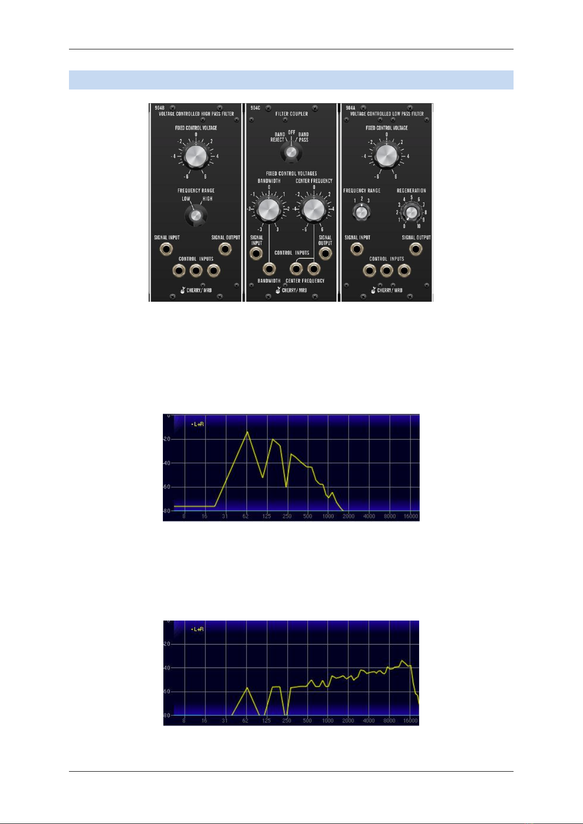
6VM904A/B/C Filters
The 904A and 904B modules are emulations of the classic transistor ladder-style low pass
and high pass filters, respectively. There are three separate modules: 904A is the classic
24dB/oct, low pass filter, 904B is a 24dB/oct high pass filter, and the 904C Filter Coupler
allows 904A and 904B to be combined for band reject and band pass responses.
Following is an explanation of how each filter type works:
A low pass filter allows frequencies below the cutoff frequency setting to pass through, but
blocks frequencies above the cutoff frequency. The frequency plot above shows the effect
of a low pass filter with its cutoff set at 412 Hz on a sawtooth wave. (The vertical axis
represents amplitude and the horizontal axis represents frequency.) You can see how the
high-frequency content trails off as it gets higher.

Voltage Modular: Cherry Audio / MRB Modules User Manual
Page 13
This plot shows the same oscillator signal and cutoff frequency setting using the high pass
mode. This is the opposite of low pass mode: high-frequency content remains, but low
frequencies are removed as the cutoff frequency increases.
The plot above shows the same oscillator signal and cutoff frequency using a band pass
filter. Band pass mode combines both low pass and high pass modes, leaving sound only "in
the middle," aka the pass band... which should not be confused with The Gap Band, who will
let frequencies across the audio spectrum pass through, and drop the bomb on you, baby.
A band reject filter is the inverse of band pass filter: a small spectrum of frequencies
between the low pass and high pass settings are eliminated. This may not seem useful, but
when the cutoff frequencies are modulated, band reject filters (also known as "notch"
filters) can be used to create nifty sweeping phaser-like sounds ("phasers" as in the guitar
stomp box effect, not the gun Capt. Kirk stunned green aliens with).
6.1 Module Configurations
The 904 modules are unique in that they can be used independently or in conjunction. As
such we've provided a couple different versions - the 904A Low Pass and 904B High Pass
filters are provided as individual modules, as well as together with the 904C Filter Coupler as
one large module. In this configuration, the low pass and high pass filters are internally
connected to the 904C Coupler, allowing band reject and band pass responses. The 904C
Filter Coupler doesn't process sound on its own; in a hardware Moog modular system, it is
internally connected to the 904A and 904B modules. Because of this, 904C isn't provided
as a single module.
6.2 Inputs, Outputs, and Controls
6.2.1 904A Voltage Controlled Low Pass Filter
Fixed Control Voltage- Sets the frequency where high-frequency attenuation begins, over a
12-octave range. This control is generally called "cutoff frequency" on just about every other
synth on the planet (remember that these designs date from the mid-60s). Turning to the
left "closes" the filter for darker tone, and turning to the right "opens" it for brighter tone.
Frequency Range- Shifts the overall range of the Fixed Control Voltage knob in two-octave
increments.
Regeneration- Also known as resonance or "Q," regeneration emphasizes sound energy at
and around the current cutoff frequency by adding feedback from the filter's output back to

Voltage Modular: Cherry Audio / MRB Modules User Manual
Page 14
its input. At lower settings, this can be used to create mild resonances such as those heard
in acoustic instruments. At more extreme settings, resonance can create a pure sine wave at
its own frequency (variable via the Fixed Control Voltage knob). Be careful with this knob as
it can get loud at extreme settings.
Signal Input jack- Patch audio signals in here.
Control Inputs jacks- CV mod inputs. These sum with the Fixed Control Voltage frequency.
Signal Output jack- The filter output signal.
6.2.2 904B Voltage Controlled High Pass Filter
Fixed Control Voltage- Sets the frequency where low-frequency attenuation begins, over a
12-octave range. This control is generally called "cutoff frequency" on just about every other
synth on the planet. Turning to the left lets more low/fundamental frequencies pass
through, and turning to the right attenuates low frequencies.
Frequency Range- Shifts the overall range of the Fixed Control Voltage knob in 1.25 octave
increments.
Signal Input jack- Patch audio signals in here.
Control Inputs jacks- CV mod inputs. These sum with the Fixed Control Voltage frequency.
Signal Output jack- The filter output signal.
6.2.3 904C Filter Coupler
As mentioned above, the 904C Filter Coupler internally connects the 904A Low Pass and
904B High Pass filter to enable band reject and band pass responses. Signals can be patched
directly to and from the coupler module when using band reject and band pass modes.
Band Reject/Off/Band Pass switch- Selects the overall filter response behavior. In the Off
position, the low pass and high pass filters are effectively disconnected and function as
normal; their respective panel signal input and output jacks can be used for signal routing.
When set to the Band Pass position, the low pass and high pass filters are connected in
series; i.e. the low pass filter removes high frequencies, and the high pass filter
simultaneously removes low frequencies, allowing the "in-between" frequencies to pass.
The Band Reject setting is the inverse of the Band Pass setting - the central frequencies
between the low pass filters are removed.
Bandwidth- Sets the frequency span of the pass band up to three octaves.
Center Frequency- Sets the central frequency.

Voltage Modular: Cherry Audio / MRB Modules User Manual
Page 15
For correct Filter Coupler control behavior, the 904A Low Pass and 904B High Pass Fixed
Control Voltage and Frequency Range controls should all be set to center position.
Setting the 904A and 904B controls differently won't hurt anything, but the coupler controls
may not behave as expected.
Signal Input jack- Patch audio signals in here.
Bandwidth jack- CV mod input affecting bandwidth.
Control Inputs jacks- CV mod inputs. These sum with the Center Frequency.
Signal Output jack- The filter output signal.
Voltage Modular: Cherry Audio / MRB Modules User Manual
Page 16
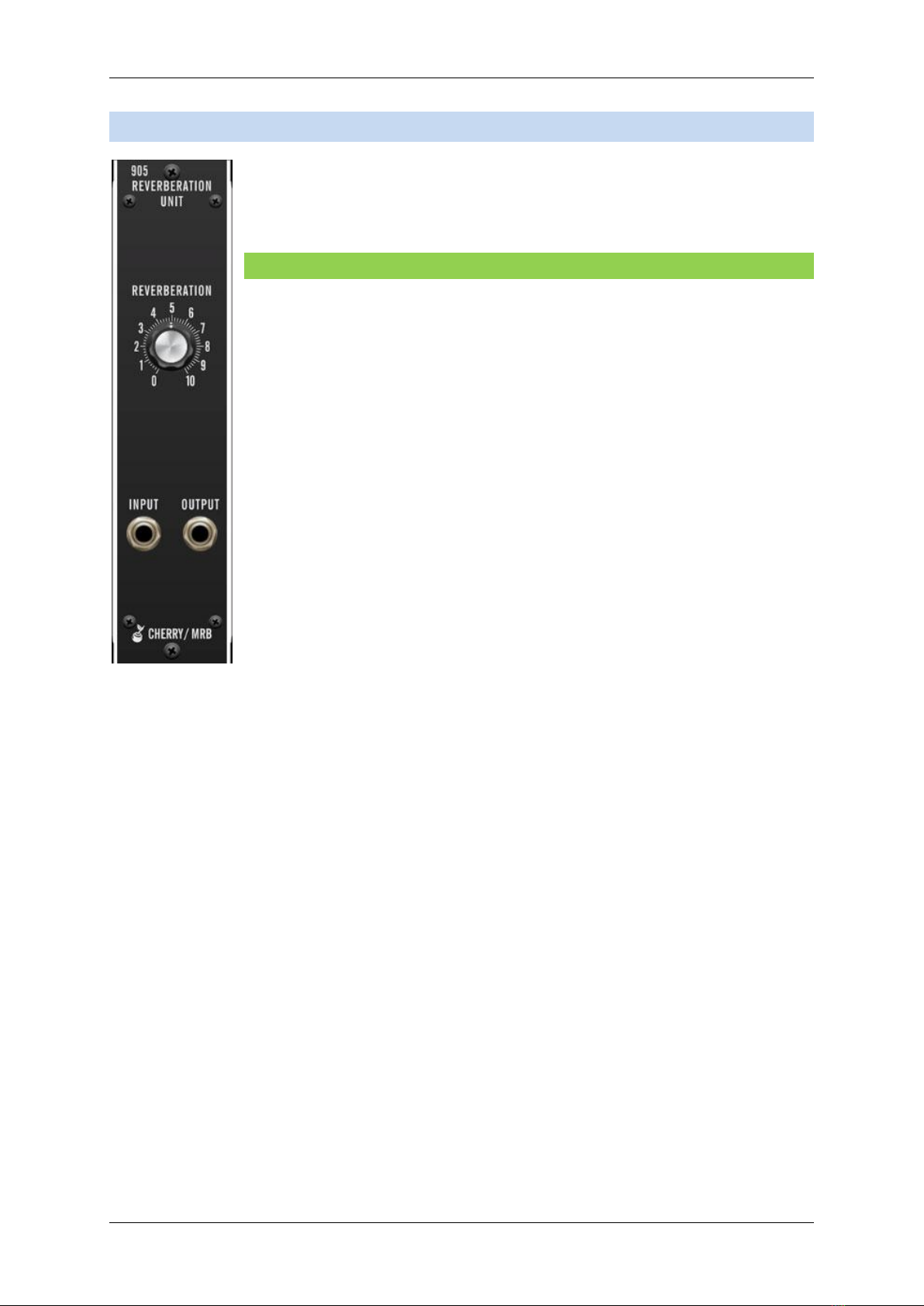
7VM905 Reverb
The VM905 is an accurate emulation of a vintage-style dual-spring reverb.
7.1 Inputs, Outputs, and Controls
Reverberation- Increases the mix level of the reverberated signal. The dry
signal always passes at 100%.
Input- Patch inputs signals here.
Output- Patch outputs signals here.
Voltage Modular: Cherry Audio / MRB Modules User Manual
Page 17
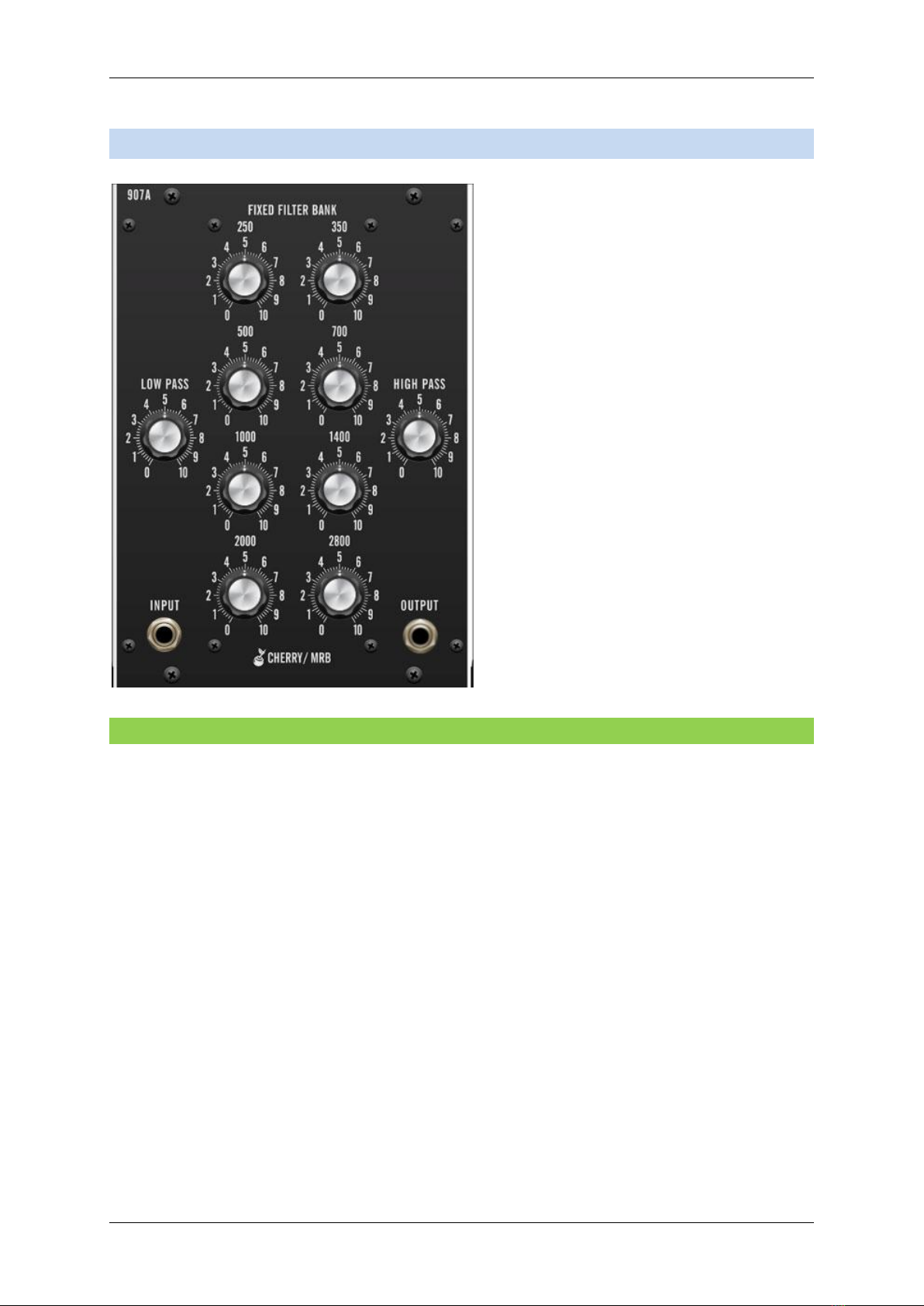
8VM907A Fixed Filter Bank
The VM907A Fixed Filter Bank consists of
eight bandpass filters that attenuate
frequencies at 1/2-octave intervals as well
as fixed corner-frequency lowpass and
highpass filters.
Its intended use is to create more realistic
instrumental sounds by imparting a
pattern of peaks and dips to the audio
spectrum of synthesizer waveforms.
8.1 Inputs, Outputs, and Controls
Lowpass- A low pass filter allows frequencies below the cutoff frequency setting to pass
through, but blocks frequencies above the cutoff frequency. This knob does not control the
cutoff frequency; it controls the volume of frequencies below the fixed 175 Hz cutoff
frequency.
Bandpass Filter volume knobs- Each of the eight main knobs corresponds to a medium-Q,
four pole, dual stagger-tuned bandpass filter. The input signal is presented to all the filters
and the knobs collectively behave like an output mixer. At zero, that channel is completely
off. When everything is turned up, all filters are heard and the response is a bumpy
spectrum with a peak at every center frequency and a dip in between.
Highpass- A high pass filter allows frequencies above the cutoff frequency setting to pass
through, but blocks frequencies below the cutoff frequency. This knob does not control the
cutoff frequency; it controls the volume of frequencies above the fixed 4000 Hz cutoff
frequency.
Input jacks- Patch audio signals in here.
Output jacks- Summed output of the fixed filter bank.
Voltage Modular: Cherry Audio / MRB Modules User Manual
Page 18
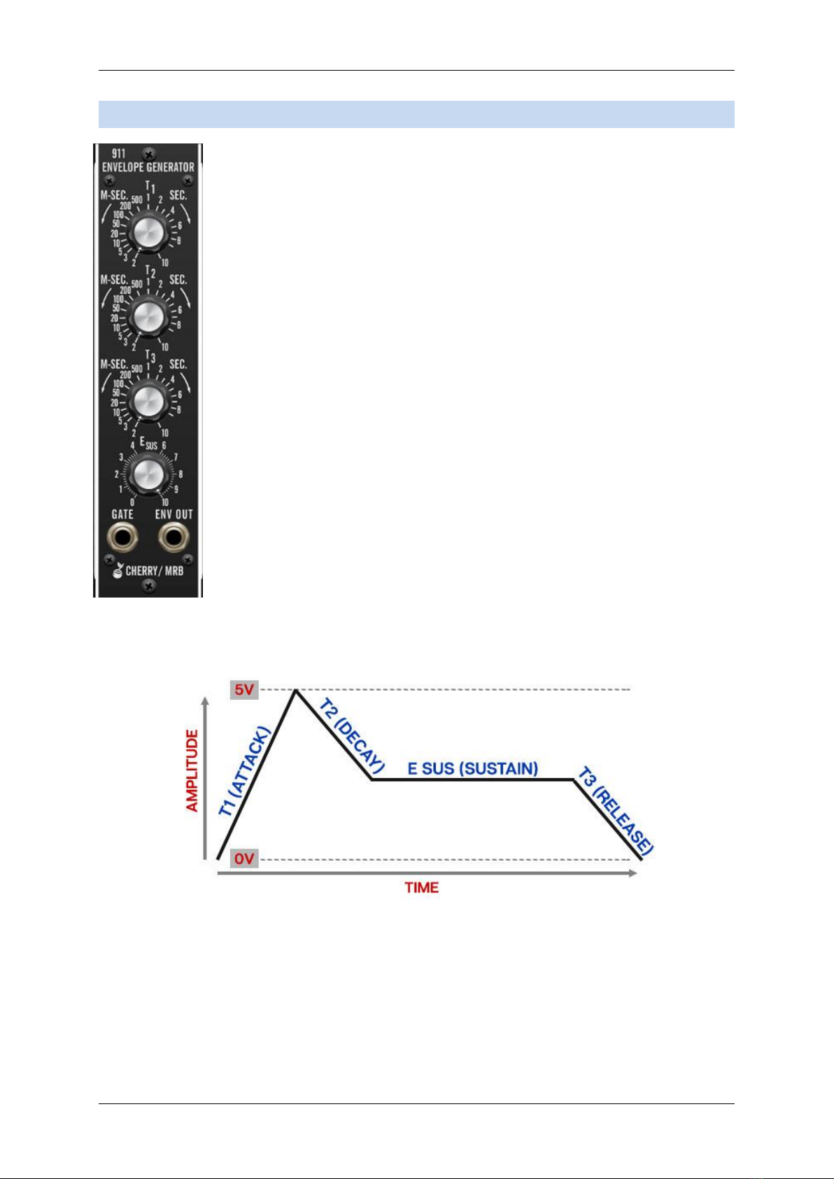
9VM911 Envelope Generator
The VM911 Envelope Generator module is a standard "ADSR"-style
envelope generator, with slightly unconventional control names.
Remember that this modules was originally developed in the mid-60s,
before analog synthesis terminology was cemented.
If you're not familiar with the operation of envelope generators, here's an overview:
When a gate voltage is sent to the Gate jack, the envelope generator outputs a voltage that
changes dynamically according to the settings of its four stages.
The T1 (attack) stage defines how long it takes for the output voltage to rise from 0 to 5
volts. Once the attack stage reaches 5V, it moves to the T2 (decay) phase, which defines
how long it takes to fall from 5V to the setting of the E Sus (sustain) phase. Unlike the T1, T2,
and T3 phases, each of which define a time, E Sus simply sets the held voltage level

Voltage Modular: Cherry Audio / MRB Modules User Manual
Page 19
following the T1 and T2 phases - this usually equates to the envelope output level while
holding down a key on a keyboard controller. Finally, the T3 knob defines the the length of
time it takes for the voltage to fall back to 0V when the gate input voltage is removed
(typically when you let go of a key on a keyboard controller).
For those interested, the T1 is (almost) linear, and T2 and T3 curve logarithmically.
(BTW, Esus is so named because E is the symbol for voltage in electro-speak. Make sure to
spout this kind of knowledge at social gatherings - we guarantee you'll be the hit of the
party.)
9.1 V-Triggers vs. S-Triggers
If you haven't used actual vintage Moog synthesizers, you can probably skip this section
with no life-altering consequences. If you're a cork-sniffin', vintage analog aficionado, this
section is ALL you.
V-triggers and S-triggers refer to two types of signal used to activate envelope generators.
The most common type is a V-trigger, more commonly referred to as a "gate" signal. This is
usually a +5V DC signal. As long as the the gate voltage is high, the envelope generator runs
through its attack and decay phases, then holds at the sustain voltage until the gate goes to
zero (typically this occurs when a key is released), at which point the envelope moves to the
release stage.
For most triggering applications, Moog used S-triggers, short for "shorting" triggers. This
was a simple switch circuit where shorting the two conductors triggered envelopes; the
envelope would run through its stages as above as long as the conductors were shorted.
When the the conductors were disconnected, the envelope would move to the release
stage. The thinking was was that any switch could be used to trigger the envelopes -
footswitches, toggles, etc.
Ultimately, S-triggers proved to be the Betamax of envelope triggering methods - just about
every modern synth uses gate signals. Additionally, in order to avoid operational calamity, S-
triggers used a non-standard, two-blade "Cinch-Jones" connector, further complicating
things.
Though we strove for accuracy in every aspect of these modules, to put it bluntly, we saw
no benefit in recreating S-triggers within the confines of the Voltage Modular environment.
The end result would have no impact on response or sound quality - it would've just
complicated interfacing with other modules. With that in mind, the Cherry Audio/MRB
VM900 modules all make use of standard gate voltages and "normal" Voltage Modular
cables for triggering purposes.

Voltage Modular: Cherry Audio / MRB Modules User Manual
Page 20
9.2 Inputs, Outputs, and Controls
T1 (Attack)- Defines the length of time for voltage to rise from 0V to 5V when the gate
voltage is applied. The time range is from 2ms to 10 seconds.
T2 (Decay)- Defines the length of time for voltage to fall from the T1 stage 5V peak to
Sustain level setting. The time range is from 2ms to 10 seconds. Also sets how long until an
Arnold Schwarzenegger cyborg storms your studio.
T3 (Release)- Defines the length of time for voltage to fall from E Sus level to 0V when the
gate is released. The time range is from 2ms to 10 seconds.
E Sus (Sustain)- Sets the held voltage level following T1 and T2 phases.
Gate jack- This is where you'll patch gate voltages to initiate the envelope generator cycle.
Most often this will come from the IO Panel Gate output.
Can I use a "trigger" to trigger an envelope generator? It would seem logical, but
the answer is, "basicallly, no." First let's clarify the difference between a gate signal
and a trigger signal:
oA gate is a constant voltage. If you're playing a keyboard, it remains high (i.e.
+5V) as long as the key is held down.
oA trigger is a rapid spike of +5V. It's useful for a number of things (like turning
stuff on and off, or triggering "one-shot" drum sounds or modules).
Though a trigger signal technically will work, it happens so quickly that the resulting
envelope generator output would be inaudible.
Like most standard envelope generators, the VM911A needs to see a constant gate voltage
to move through the T1 and T2 phases and hold during the E Sus phase. Removing the gate
voltage following the E Sus phase instantly jumps to the T3 stage.
Env Out- This is the envelope voltage output. The Env Out voltage ranges from 0V to +5V.
This manual suits for next models
23
Table of contents
Other CHERRY AUDIO Music Equipment manuals


