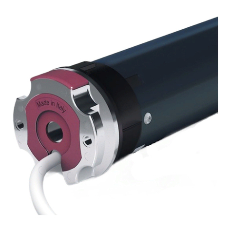
CHERUBINI WAVE RX V25 User manual

WAVE RX V25
ISTRUZIONI - INSTRUCTIONS - EINSTELLANLEITUNGEN
INSTRUCTIONS - INSTRUCCIONES
I
GB
D
F
E
VARIANTE 25:
specifico per tende
ad aggancio automatico
VERSION 25:
specific for Pergola-Awnings
with automatic coupling
MODELL 25:
speziell zu Senkrechtmarkisen
mit Einhak-System
VARIANTE 25:
spécifique pour stores
à accrochage automatique
VARIANTE 25:
específico para toldos
con enganche automático
PROGRAMMAZIONE FILARE - WIRE PROGRAMMING
DRAHTGEBUNDENE PROGRAMMIERUNG
PROGRAMMATION FILAIRE - PROGRAMACIÓN DESDE EL PULSADOR


Table of contents
Safety instructions / Warnings for user.................................................................... p. 18
Warnings for installer ............................................................................................. p. 19
How to prepare the motor ...................................................................................... p. 20
Electrical connections ............................................................................................. p. 21
Choice of the programming modes ........................................................................ p. 22
Activation/deactivation of the remote control function .......................................... p. 22
Key to symbols........................................................................................................ p. 23
Command sequences example ............................................................................... p. 23
Motor programming from the white wire .............................................................. p. 24
Note for operation from the button switch ............................................................. p. 24
Setting of the limit switches.................................................................................... p. 24
Setting the closing limit switch............................................................................... p. 24
Setting the opening limit switch ............................................................................. p. 25
Deleting the limit switch positions.......................................................................... p. 26
Deleting the closing limit switch ............................................................................ p. 26
Deleting the opening limit switch ........................................................................... p. 26
Total deleting of the limit switches ........................................................................ p. 27
Setting/deleting a middle position .......................................................................... p. 28
Adjustment of the coupling / super-sensitivity force ............................................... p. 29
Super-sensitivity obstacle detection management during downwards movement
-Only for motors up to 25 Nm-................................................................................ p. 30
Super-sensitivity threshold setting .......................................................................... p. 30
EU declaration of conformity ................................................................................. p. 73
17
TRANSLATION OF THE ORIGINAL INSTRUCTIONS
ENGLISH

18
ENGLISH
TRANSLATION OF THE ORIGINAL INSTRUCTIONS
WARNING: Important safety instructions
It is important for everyone’s safety to follow these instructions in full.
Keep these instructions for future reference.
- The tubular motors have been designed for the automation of solar protections like roller
shutters, screen, awnings, vertical awnings a.s.o. Any other use is improper. Special applications
shall be submitted to Cherubini S.p.A.’s analysis and approval.
Useful suggestions on motor choice are available on the website www.cherubini.it.
- Only professional technicians must perform installation, complying with all safety instructions,
especially those regarding electrical connections.
- This appliance can be used by children aged from 8 years and above and persons with reduced
physical, sensory or mental capabilities or lack of experience and knowledge if they have been
given supervision or instruction concerning use of the appliance in a safe way and if they
understand the hazards involved. Children shall not play with the appliance. Cleaning and user
maintenance shall not be made by children without supervision.
- Do not allow children to play with xed control devices. Keep remote controls out of the reach of
children.
- Shutters: watch the moving shutter and keep people away until the shutter is completely closed;
take care when operating the manual release with shutter open since it may fall rapidly due to
weak or broken springs.
- Awnings: Do not operate the awning when maintenance, such as window cleaning, is being
carried out in the vicinity.
- Disconnect the automatically controlled shutter/awning from the supply when maintenance,
such as window cleaning, is being carried out in the vicinity.
- Check the system frequently in order to detect any out-of-balance condition or signs of wear. Do
not use the motorized unit if it needs repair or adjustment.
- The supply cord of this motor can be replaced only by the same type of cable supplied by
Cherubini S.p.A.
- The acoustic emission level of Cherubini S.p.A. motors is lower than 70dBA: LpA < 70dB(A).
- The choice of the motor, based on its application requirements, shall be compatible with the data
written on the motor label. The trade name of the product is printed on the label.
Every motor model is identied by a part number on the packaging label. The part number is
described in the motor catalog available on the website www.cherubini.it.
WARNING: the motor shall be disconnected from its power source during cleaning,
maintenance and when replacing parts.
- Only professional technicians must perform maintenance and repairs.
- If the supply cord is damaged please call the assistance centre or qualied technical staff,
in order to avoid any hazard.
- The tubular motor is designed to work non-stop for a maximum of 4 minutes.
- Do not squash, crush, drop or wet the tubular motor with any kind of liquid; do not pierce and
do not apply any screw along the tubular section.
- The guarantee does not cover any damage caused by misuse, straining, tampering or incorrect
connections.
WARNINGS FOR USER

19
ENGLISH
- The choice of the motor, in its use application, must be compatible with the rating marked on
the motor itself. For further technical information, refer to product data sheet on the website
www.cherubini.it or contact your local Cherubini representative (see the last page of this
manual for the addresses).
- The mass and the dimension of the driven part shall be compatible with the rated torque and
related operating time. Nominal torque and operating time are given on the motor rating label,
in Nm and min. units respectively.
- The minimum diameter of the tube on which the motor can be installed is related to its
proper external diameter. The values to be considered are the rst two part number digits (e.g.
AMP35xxxxxx, AME45xxxxxx, AME58xxxxxx). The tube must have a minimum diameter not
lower than the following values: 40 mm (for motors identied with 35), 50 mm (45), 70 mm (58)
-
For outdoor exposure provide to protect the supply cord by inserting it into a cable duct. motor
with 60245 IEC 53 (H05RR-F) or 60245 IEC 57 (H05RN-F) designated supply cord shall be installed.
- Before installing the drive motor, remove any unnecessary cable and disconnect any equipment
not required for the working of the motor itself.
- Before each maintenance intervention, installation or window cleaning switch off the motor
power supply.
- The actuating member of a biased-off switch is to be located within direct sight of the driven part
but away from moving parts. It is to be installed at a minimum height of 1.5 m and not accessible
to the public.
- If the motor is tted with the emergency manual operation device, the length of the rod must
ensure that the crank is at a height below 1.8 metres.
- Fixed controls have to be clearly visible after installation.
- If the motor is used to move sun awnings, keep a safety horizontal distance of at least 40 cm
between the fully opened awning and any permanent object.
- If the supply cord is damaged, it must be replaced by Cherubini Service in order to prevent any
risk.
- Connection devices, supports and adaptors are not supplied with our motors but separately. For
use and choice consult the Cherubini “Tubular motors” catalogue (see www.cherubini.it).
- During connection follow the instructions thoroughly. If you have any doubt, NEVER act at
random but consult competent technicians.
- The guarantee does not cover any damage caused by misuse, straining, tampering or incorrect
connections.
WARNINGS FOR INSTALLER
WARNING: Important safety instructions.
Follow all instructions, since incorrect installation can lead to severe injury.
NO NO NO NO NO

20
I
HOW TO PREPARE THE MOTOR
NB: If you use tubes with a round form, the driving pulley must be xed to the tube, and
the installation is to be paid by the person who installs the system. For other tube sections
the tting is optional, but strongly recommended.
1. Insert the adaptor in the stop ring nut
mating the groove with the reference notch
and push till they touch.
2. Fix the driving pulley on the motor pin
until the stop pin clicks.
3. Insert the motor fully in the rolling tube.
STOP RING NUT ADAPTOR
DRIVING PULLEY
STOP RING NUT
1
2
3
ENGLISH

I
21
Switch with mechanical
or electrical interlocking
1- brown
2- white
3- blue
4- green-yellow
ELECTRICAL CONNECTIONS
- In order to prevent dangerous situations or malfunctioning, the electrical command
elements wired to the motor must be sized according to the motor’s electrical features.
- Means for disconnection must be incorporated in the xed wiring in accordance with
the national installation standards.
- For outdoor use, provide the appliance with a supply cable with designation H05RN-F
containing at least 2% of carbon.
- If not used, the white wire must be insulated. It is dangerous to touch the white wire
when the motor is powered.
NOTE FOR
OPERATION FROM
THE BUTTON SWITCH
- see pag. 24
ENGLISH

CHOICE OF THE PROGRAMMING MODES:
RADIO - WHITE WIRE - WHITE WIRE with the radio function active
he Wave RX motor may be programmed using 3 modes:
- RADIO PROGRAMMING: Once the programming has been completed the motor enables
use either by white-wire, by radio, or using both modes (radio/wire).
- WHITE WIRE PROGRAMMING:
· After the adjustment of the limit switches using the white wire, programming remains
active for 5 min. After 5 min have elapsed, the motor must be disconnected from its
power supply and then reconnected in order to reprogram the system.
· If the limit switches are set using the whitewire without programming a remote
control, the radio function is automatically deactivated for programming and for later
use. To reset the radio function, the activation sequence found on this page must be
performed within 5 min from the adjustment of the limit switches (or after having
disconnected and then reconnected the motor from its power supply).
· Once the programming has been completed the motor enables only the use of the
white wire, unless the radio function is reactivated.
- WHITE WIRE PROGRAMMING WITH RADIO FUNCTION ACTIVE: To be able to use both
modes (radio and wire), a remote control must be programmed before the adjustment of
the limit switches in the white wire mode. Once the programming has been completed
the motor enables use either by white wire, by radio, or using both modes (radio/wire).
ACTIVATION/DEACTIVATION OF THE REMOTE CONTROL FUNCTION
To activate/deactivate the remote control function, follow the sequence shown below:
PLEASE NOTE: To deactivate the remote function it is rst necessary to totally delete the
remote controls from the memory of the motor (Wave RX manual).
Activation/deactivation from the CLOSING position:
Activation/deactivation from the OPENING position:
22
The conrmation movements indicate that the remote control function activation/
deactivation procedure has been successfully carried out.
ENGLISH

23
down
up
KEY TO SYMBOLS
UP DOWN
Press the UP-
button
Press the buttons quickly according to the sequence indicated
Press the buttons quickly according to the sequence indicated.
The motor will carry out a movement to conrm your settings.
Press the
DOWN-button
DOWN DOWNUP
DOWN DOWNUP
short motor
rotation in one
direction
long motor
rotation in
other direction
COMMAND SEQUENCES EXAMPLE
Most of the command sequences have three or six distinct steps, at the end of which the
motor indicates if the step has been concluded positively or not, by turning in different
ways.This section is provided to demonstrate the motor indications. The buttons must be
pressed for at least 0,5 seconds as shown in the sequence, without taking more than 1
second between one step and the next. If more than 1 second is taken, the command is
not accepted and the sequence must be repeated.
Command sequence example:
As we can see from the example, when the sequence ends positively, the motor carries
out one long rotation.
If the motor does not carry out any rotation, this means that the sequence has failed. In
this case the sequence must be carried out again from the start.
Attention! If the sequence requires a repetition of the same commands (Up+Up/
Down+Down), an interposition of the Stop position could be necessary depending
on the type of switch in use.
UPUP UP
ENGLISH

24
MOTOR PROGRAMMING FROM THE WHITE WIRE
PLEASE NOTE. If the motor is programmed from the white wire without rst having
memorised at least one remote control, the remote function will be deactivated
automatically (to reactivate it, see page 22 - ACTIVATION/DEACTIVATION OF THE
REMOTE CONTROL MOTOR FUNCTION).
Motor programming from the white wire is active until the limit switches have been
programmed. Once the limit switches have been programmed, the possibility of
programming the motor from the white wire remains enabled for a maximum time of 5
minutes; this to enable the changing of certain functions such as the adjustment of the
closing force, the middle position, etc.
Each time that the motor power supply is disconnected and the motor is then powered
up again, the programming function from the white wire is reactivated (always with a
maximum duration of 5 minutes).
NOTE FOR OPERATION FROM THE BUTTON SWITCH
The motor automatically recognizes the switch-type (with 1 or 2 buttons) and sets the
proper operational mode. Following the automatic recognition and after the wire setting,
if required the motor changes the association of the switch buttons to adapt them to the
correct drive direction (Up - Down). At this point, if the drive direction does not match
with the buttons, the motor resets the proper association upon the rst complete Up/
Down cycle. During this cycle the motor performs a technical stop and then automatically
starts back up.
ENGLISH
SETTING OF THE LIMIT SWITCHES
During adjustment the motor will advance with a short movement and then a pause
followed by a continuous movement in the desired direction. The limit switch may be
adjusted regardless of the fact that the motor is mounted in a box awning or square bar.
SETTING THE CLOSING LIMIT SWITCH
It’s necessary to set rst the closing position! For cassette-awnings, hold the button
pressed until the motor stops automatically on the closing position. For open awnings,
hold the button pressed and drive until the necessary closing position.
Notes:
If the awning is completely closed, you have rstly to open it by around 20 cm.
Because the correct rotation direction will be identied only after the closing position is
set, to close the awning, during setting the closing position, it’s sometimes necessary to
use the “down” button.

25
Bring the awning to the closing position using the UP or DOWN button.
Follow the command sequence given in order to save the closing position. At the end of
the sequence, the motor carries out a short “down” movement which conrms that the
settings have been saved.
ENGLISH
UPUP UP
conrm
?
DOWN
UP
?
DOWN
UP
SETTING THE OPENING LIMIT SWITCH
• Put the Pergola at its “lowest coupling limit” position
(g. 1)
.
• Perform the sequence DOWN+DOWN+DOWN until the motor lifts the fabric into its
coupling position
(g. 2)
.
• Press the button DOWN to put the fabric on position “lowest uncoupling limit”
(g. 3)
.
• Perform the sequence DOWN+DOWN+DOWN until the motor lifts the fabric and ends
the uncoupling movement
(g. 4)
.
• From now to move the motor, just press either the up or down buttons briey.
Coupling
Lowest coupling
limit
2
Lowest uncoupling
limit
3
Pergola closed
1
1
3
2
Fig. 3 1
3
2
Fig. 4
1
3
2
Fig. 1 1
3
2
Fig. 2

DELETING THE LIMIT SWITCH POSITIONS
DELETING THE CLOSING LIMIT SWITCH
From the CLOSING position
From the OPENING position
26
ENGLISH
After deleting the closing limit switch, it is possible to proceed to a new adjustment and
memorization of the closing position.
The motor is now running in “Dead Man” mode. To memorise a new closing position refer
to the procedure “SETTING THE CLOSING LIMIT SWITCH” see page 24.
The motor is now running in “Dead Man” mode. To memorise a new opening position
refer to the procedure “SETTING THE OPENING LIMIT SWITCH” see page 25.
DELETING THE OPENING LIMIT SWITCH
From the CLOSING position
From the OPENING position
After deleting the opening limit switch it is possible to proceed to a new adjustment and
memorization of the opening position.

27
TOTAL DELETING OF THE LIMIT SWITCHES
From the CLOSING position
From the OPENING position
After deletion of the limit switches the radio function automatically resets.
ENGLISH

28
SETTING/DELETING A MIDDLE POSITION
From the CLOSING position
From the OPENING position
From the CLOSING position
From the OPENING position
After the sequence the motor will go into “Dead Man” mode so as to enable the exact
adjustment of the middle position desired. To memorise the position chosen, conrm
with this sequence:
DELETING THE MIDDLE POSITION
Use one of the sequences shown here.The motor will conrm with 3 nal movements that
the middle position has been cancelled.
To bring the awning to the middle
position do the following: or
SETTING THE MIDDLE POSITION
MOVEMENT TO MIDDLE POSITION
ENGLISH

29
ADJUSTMENT OF THE COUPLING / SUPER-SENSITIVITY FORCE
During coupling the motor stops automatically on torque, as soon as the fabric is in
tension charge.
The level of the coupling tension may be selected on three levels and may be chosen using
following procedure:
From the CLOSING position
DOWNUPUP
DOWN DOWN UP
DOWN UP UP
DOWNDOWNUP
DOWN DOWN UP
DOWNUPUP
DOWN DOWN DOWN
UP UPUP
40 %
40 %
70 %
70 %
From the OPENING position
conrm
conrm
ENGLISH
The Wave RX V25 motor is set in the factory with a coupling force of 20% of the nominal
torque (e.g., 20% of 50 Nm = 10 Nm). Using the button switch this level can be switched
to 40% or 70% depending on the results that you wish to achieve.
20 %
20 %

30
SUPER-SENSITIVITY OBSTACLE DETECTION MANAGEMENT
DURING DOWNWARDS MOVEMENT
-only for motors up to 25 Nm-
ACTIVATING THE SUPER-SENSITIVITY FUNCTION
From the CLOSING position
From the OPENING position
DEACTIVATING THE SUPER-SENSITIVITY FUNCTION
The activating and deactivating sequences are the same but the motor feedback
is different.
ENGLISH
SUPER-SENSITIVITY THRESHOLD SETTING
If the super-sensitivity function on obstacle detection downward is activated, it is
possible to set a sensitivity threshold through the sequences illustrated in the section
“ADJUSTMENT OF THE COUPLING / SUPER-SENSITIVITY FORCE” (see page 29).
Ex: 20% = lowest threshold = maximum downward sensitivity (set in the factory)
40% = medium threshold = medium downward sensitivity
70% = highest threshold = minimum downward sensitivity
To re-adjust the hooking strength, it is always mandatory to deactivate the
super-sensitivity function.

73
CHERUBINI S.p.A. dichiara che il prodotto è conforme alle pertinenti normative di
armonizzazione dell’Unione:
Direttiva 2014/53/UE, Direttiva 2011/65/UE.
Il testo completo della dichiarazione di conformità UE è disponibile facendone
richiesta sul sito: www.cherubini.it.
IDICHIARAZIONE DI CONFORMITÀ UE
CHERUBINI S.p.A. declares that the product is in conformity with the relevant Union
harmonisation legislation:
Directive 2014/53/EU, Directive 2011/65/EU.
The full text of the EU declaration of conformity is available upon request at the
following website: www.cherubini.it.
GB EU DECLARATION OF CONFORMITY
CHERUBINI S.p.A. erklärt der produkt erfüllt die einschlägigen
Harmonisierungsrechtsvorschriften der Union:
Richtlinie 2014/53/EU, Richtlinie 2011/65/EU.
Der vollständige Text der EU-Konformitätserklärung kann unter unserer Web-Seite
www.cherubini.it, gefragt werden.
DEU-KONFORMITÄTSERKLÄRUNG
CHERUBINI S.p.A.déclare que le produit est conforme à la législation d’harmonisation
de l’Union applicable:
Directive 2014/53/UE, Directive 2011/65/UE.
Le texte complet de la déclaration UE de conformité est disponible en faisant requête
sur le site internet: www.cherubini.it.
FDÉCLARATION UE DE CONFORMITÉ
CHERUBINI S.p.A. declara que el producto es conforme con la legislación de
armonización pertinente de la Unión:
Directiva 2014/53/UE, Directiva 2011/65/UE.
El texto completo de la declaración UE de conformidad puede ser solicitado en:
www.cherubini.it.
EDECLARACIÓN UE DE CONFORMIDAD

Note - Bem - Notes - Notas:


Rev: 2 04/2018 - Cod: A4518_6E23
CHERUBINI Deutschland GmbH
Siemensstrasse, 40 - 53121 Bonn - Deutschland
Tel. +49 (0) 228 962 976 34 / 35 | Fax +49 (0) 228 962 976 36
info@cherubini-group.de | www.cherubini-group.de
CHERUBINI France S.a.r.l.
ZI Du Mas Barbet
165 Impasse Ampère
30600 Vauvert -France
Tél. +33 (0) 466 77 88 58 | Fax +33 (0) 466 77 92 32
info@cherubini.fr | www.cherubini.fr
CHERUBINI Iberia S.L.
Avda. Unión Europea 11-H
Apdo. 283 - P. I. El Castillo
03630 Sax Alicante - Spain
Tel. +34 (0) 966 967 504 | Fax +34 (0) 966 967 505
info@cherubini.es | www.cherubini.es
CHERUBINI S.p.A.
Via Adige 55
25081 Bedizzole (BS) - Italy
Tel. +39 030 6872.039 | Fax +39 030 6872.040
info@cherubini.it | www.cherubini.it
Table of contents
Other CHERUBINI Window Blind manuals
Popular Window Blind manuals by other brands

FIBARO
FIBARO ROLLER SHUTTER 3 manual

HunterDouglas
HunterDouglas Silhouette Installation operation care

Silent Gliss
Silent Gliss SG 1032 installation instructions

DEZ Furnishings
DEZ Furnishings QJBK quick start guide

my home
my home Malin Assembly instructions

Silent Gliss
Silent Gliss SG 1012 installation instructions

Shade Elements
Shade Elements Omni Screen quick start guide

VENETA
VENETA 65101-50725-D How to install

SKILTEC
SKILTEC LUXAFLEX LUMINETTE Installation operation care

MHZ
MHZ R 03 Installation and operating instructions

CHILD SAFETY
CHILD SAFETY arzion outdoor Mounting instruction

MHZ
MHZ 11-8110 Installation and operation instruction