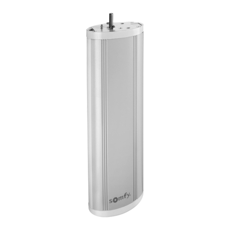
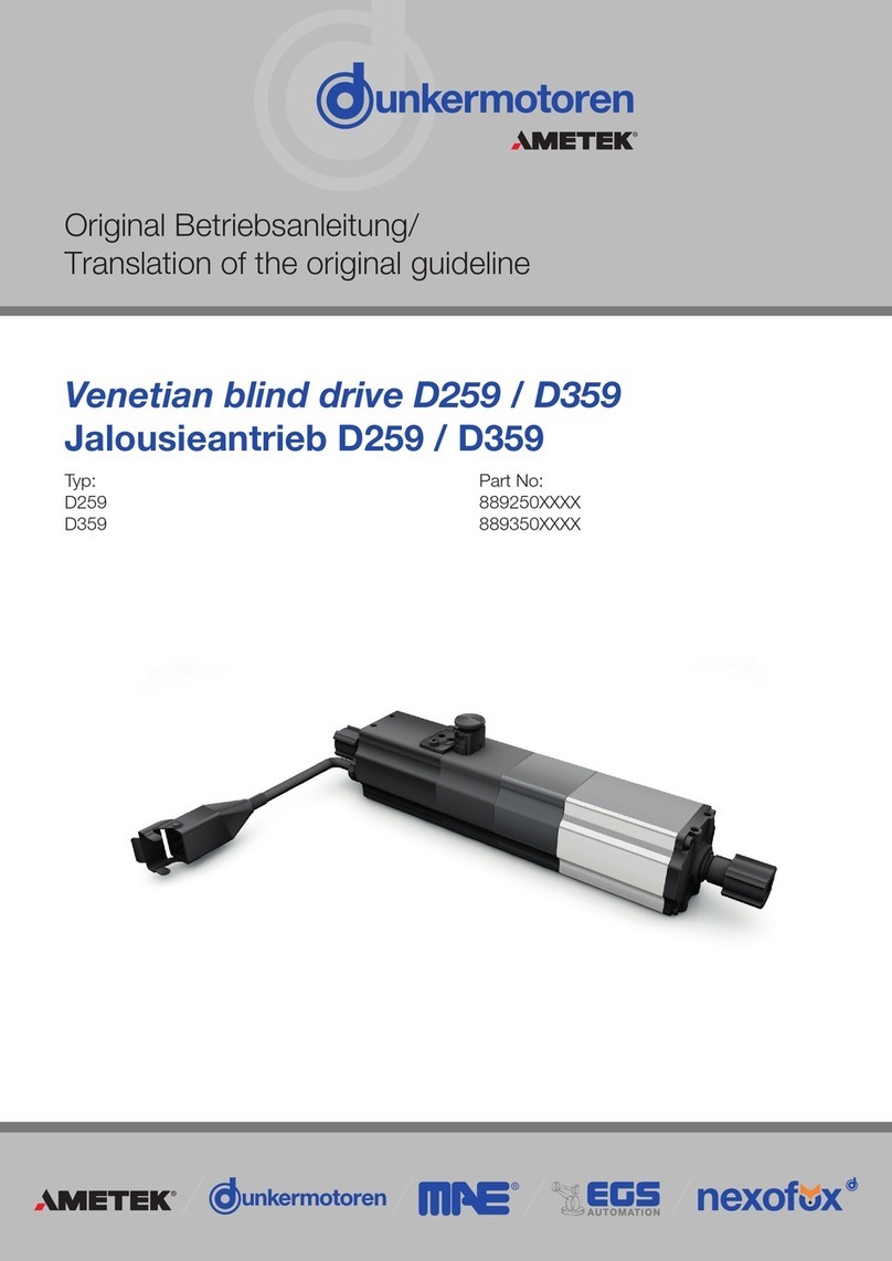
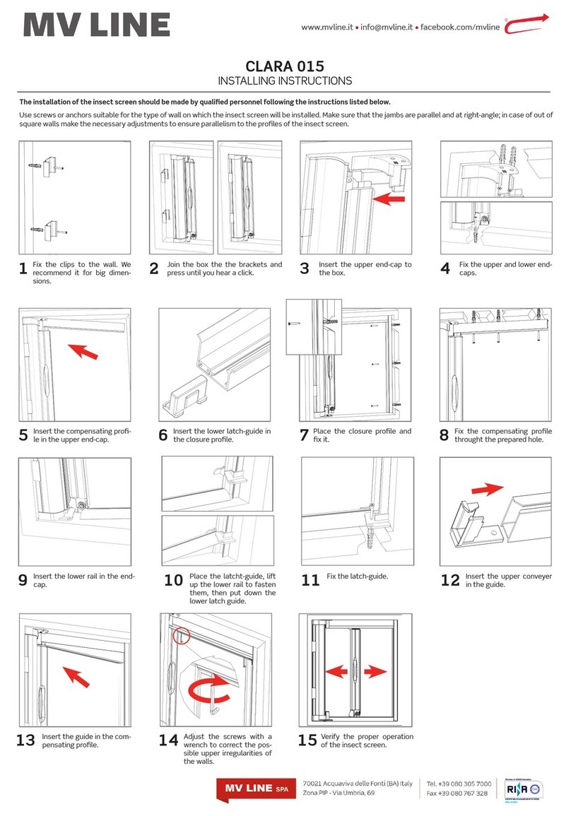
Ametek Dunkermotoren DCD22 User manual

Venetian blind drive DCD22/
Jalousettenantrieb DCD22
Original Betriebsanleitung/
Translation of the original guideline
Typ:
DCD22-2-G
DCD22-2-E
Control unit with Adapter cable for
DCD22-E-2/
Bediengerät DCD22-E-2
und Adapterkabel für DCD22-E-2
Part No:
88961.03XXX
88961.04XXX
49797.59790 and 27573.38230

Page/Seite 2 / 37 DCD22-2-G / DCD22-2-E Version 20-12-2022
Inhalt
1. Zu dieser Dokumentation...................... 4
1.1 Haftung und Gewährleistung............................... 5
1.2 Zielgruppe........................................................... 5
1.3 Sicherheitshinweise............................................. 5
1.4 Weitere Piktogramme.......................................... 6
1.5 Gefahrenzeichen ................................................. 6
1.6 EG-/EU-Konformitätserklärung............................ 7
1.7 Richtlinie Niederspannungsrichtlinie
(NSR) 2014/35/EU .............................................. 7
2. Sicherheitshinweise............................... 8
2.1 Bestimmungsgemäße Verwendung..................... 8
2.2 Vorhersehbarer Fehlgebrauch ............................. 8
2.3 Grundlegende Sicherheitshinweise...................... 9
2.4 Sicherheitshinweise für Personal ......................... 9
2.5 Sicherheitshinweise zu Betriebsphasen............. 10
2.5.1 Transport........................................................... 10
2.5.2 Installation ......................................................... 10
2.5.3 Reinigung.......................................................... 10
2.5.4 Wartung/Reparatur............................................ 10
2.5.5 Umweltgerecht entsorgen ................................. 10
2.6 Hinweise auf besondere Gefahrenarten ............ 11
2.6.1 Elektrische Energie/elektromagnetische
Sicherheit .......................................................... 11
2.6.2 Mechanische Sicherheit..................................... 11
3. Transport und Lagerung...................... 12
4. Produktbeschreibung.......................... 13
4.1 Aufbau DCD22-2-G und DCD22-2-E ................ 13
4.2 Aufbau Bediengerät für DCD22-2-E .................. 14
Content
1. About this Documentation .................... 4
1.1 Liability and Warranty .......................................... 5
1.2 Target Group....................................................... 5
1.3 Safety Notes ....................................................... 5
1.4 Further Icons....................................................... 6
1.5 Hazard Signs ...................................................... 6
1.6 EC-/EU Declaration of Conformity....................... 7
1.7 Directives Low-Voltage Directive
(LVD) 2014/35/EU ............................................... 7
2. Safety Notes........................................... 8
2.1 Intended Use ...................................................... 8
2.2 Expected Misuse ................................................ 8
2.3 Basic Safety Notes.............................................. 9
2.4 Safety Notes for Staff .......................................... 9
2.5 Safety Notes concerning Operating Phases ...... 10
2.5.1 Transport........................................................... 10
2.5.2 Installation ......................................................... 10
2.5.3 Cleaning............................................................ 10
2.5.4 Maintenance/Repair .......................................... 10
2.5.5 Environmentally Compatible Disposal ................ 10
2.6 Notes concerning Special Hazard Types ........... 11
2.6.1 Electrical Energy/Electromagnetic
Safety................................................................ 11
2.6.2 Mechanical Safety ............................................. 11
3. Transport and Storage......................... 12
4. Product Description............................. 13
4.1 Design DCD22-2-G and DCD22-2-E ................ 13
4.2 Design Venetian Blind Drives series DCD22....... 14

Version 20-12-2022 DCD22-2-G / DCD22-2-E Page/Seite 3 / 37
5. Technische Daten ................................ 15
5.1 Produktspezifikation.......................................... 15
5.2 Umgebungsbedingungen ................................. 16
5.3 Maßzeichnung DCD22-G.................................. 17
5.4 Maßzeichnung DCD22-E................................... 18
5.5 Drehmoment/Stromkennlinie............................. 19
5.6 Typenschild ...................................................... 20
6. Installation ............................................ 21
6.1 Mechanische Montage...................................... 21
6.2 Elektrische Montage.......................................... 22
6.3 Anschlussbelegung DCD22-2-E........................ 25
6.4 Anschlusskabel DCD22-2-E.............................. 26
6.5 Anschlusskabel DCD22-2-G ............................. 26
6.6 Einzelanschluss DCD22-2-E ............................. 27
6.7 Paralleler Anschluss DCD22-2-E....................... 27
6.8 Logikversorgung, Ein- und Ausgänge................ 28
6.9 Adapterkabel für Bediengerät DCD22-2-E ........ 29
6.10 DCD22-2-E mit Bediengerät einstellen .............. 30
6.10.1 Einstellen der oberen Endlage ........................... 30
6.10.2 Einstellen der unteren Endlage........................... 31
6.10.3 Wiederherstellen des Auslieferzustandes........... 32
6.11 Normalbetrieb DCD22-2-E................................ 33
6.12 Verhalten im Betrieb ......................................... 33
7. Wartung ................................................ 35
8. Außerbetriebnahme und Entsorgung 35
9. Service und Support............................ 35
10. Impressum............................................ 36
5. Technical Data...................................... 15
5.1 Product specification......................................... 15
5.2 Environmental Conditions.................................. 16
5.3 Dimensional Drawing DCD22-G ........................ 17
5.4 Dimensional Drawing DCD22-E......................... 18
5.5 Torque/current characteristic............................. 19
5.6 Motor label........................................................ 20
6. Installation ............................................ 21
6.1 Mechanical Assembly........................................ 21
6.2 Electrical Assembly ........................................... 22
6.3 Pin assignment DCD22-2-E .............................. 25
6.4 Connection Cable DCD22-2-E.......................... 26
6.5 Connection Cable DCD22-2-G ......................... 26
6.6 Single Connection DCD22-2-E.......................... 27
6.7 Connecting in parallel DCD22-2-E..................... 27
6.8 Logic Supply, Inputs and Outputs ..................... 28
6.9 Adapter cable for control unit DCD22-2-E......... 29
6.10 DCD22-2-E set with control unit........................ 30
6.10.1 Setting of the upper end position....................... 30
6.10.2 Setting of the lower end position ....................... 31
6.10.3 Re-establishing of the delivery state................... 32
6.11 Normal operation DCD22-2-E........................... 33
6.12 Behaviour during operatio ................................. 33
7. Maintenance......................................... 35
8. Decommissioning and Disposal......... 35
9. Service and Support ............................ 35
10. Imprint................................................... 36

Page/Seite 4 / 37 DCD22-2-G / DCD22-2-E Version 20-12-2022
1. Zu dieser Dokumentation
Diese Dokumentation richtet sich an Personen, die mit
Transport, Montage und Anschluss des Motors beauftragt
sind.
Im nachfolgenden wird der DCD22-2-G bzw. DCD22-2-E
als „Produkt“ bezeichnet.
XLesen Sie die Anleitungen und Informationen sorgfäl-
tig durch.
XBeachten Sie die Sicherheitshinweise im Dokument
und am Produkt.
XVerwenden Sie das Produkt nur im technisch ein-
wandfreien Zustand.
XBewahren Sie die Dokumentation griffbereit am Ein-
satzort auf.
XBeachten Sie ergänzend gültige gesetzliche und sons-
tige verbindlichen Regelungen zur Unfallverhütung und
zum Umweltschutz.
Zusätzlich zu dieser Dokumentation für Einstellung und
Parametrierung des Motors ist die Montageanleitung, die
dem Produkt beiliegt erforderlich. Diese und weiterführen-
de Informationen sowie die Konformitätserklärung, finden
Sie auch auf unserer Homepage unter www.dunkermoto-
ren.de.
Folgende Dokumente zu Ihrem Motor sind auf Anfrage bei
Dunkermotoren erhältlich:
»Spezifikation und Kennlinie.
»Maßzeichnungen.
1. About this Documentation
This documentation is targeted at people who are
charged with transport, assembly and connection of the
motor.
In the following, the DCD22-2-G and DCD22-2-E is refer-
red to as „product“.
XRead the instructions and information carefully.
XObserve the safety notes in the document and on the
product.
XUse the product only if it is in a technically impeccable
condition.
XKeep the documentation ready at hand at the site of
use.
XAdditionally observe any applicable statutory and other
binding provisions on accident prevention and environ-
mental protection.
The assembly instructions enclosed with the product are
required in addition to this documentation for adjustment
of the motor. This and further information, as well as the
declaration of conformity, can be found on our website
under www.dunkermotoren.com.
The following documents concerning your motor are avai-
lable from Dunkermotoren on request:
»Specification and characteristic curve.
»Dimensional drawings.

Version 20-12-2022 DCD22-2-G / DCD22-2-E Page/Seite 5 / 37
1.1 Liability and Warranty
Dunkermotoren GmbH does not accept any liability or
warranty claims for personal injury or damage to property
if they are attributable to one or several of the following
causes:
»The product was not properly commissioned, set up
or handled.
»Notes in the documentation concerning safety, trans-
port, storage, assembly, commissioning, programming
or operation of the product were not observed.
»The product was modified without the advance con-
sent and written approval of Dunkermotoren GmbH.
»Application of externally acquired spare and wear
parts.
Wear parts are excluded from the warranty.
1.2 Target Group
This function and connection guide is targeted only at
qualified and trained specialists with knowledge in electro-
nics, mechanics and drive technology.
1.3 Safety Notes
The safety notes inform about potential hazards and
name measures to avoid risks.
The safety notes are structured as follows:
DANGER DANGER marks hazards that will
directly lead to death or severe
injury.
WARNING WARNING marks hazards that
may lead to death or severe
injury.
CAUTION CAUTION marks hazards that
may lead to injury.
NOTICE NOTICE marks hazards that
may lead to property damage.
1.1 Haftung und Gewährleistung
Die Dunkermotoren GmbH übernimmt keine Haftungs-
und Gewährleistungsansprüche für Personen- und Sach-
schäden, wenn sie auf einen oder mehrere der folgenden
Ursachen zurückzuführen sind:
»Produkt wurde nicht richtig in Betrieb genommen, ein-
gerichtet oder bedient.
»Hinweise in der Dokumentation bezüglich Sicherheit,
Transport, Lagerung, Montage, Inbetriebnahme, Pro-
grammierung oder Betrieb des Produkts wurden nicht
beachtet.
»Eine Modifikation des Produktes wurde ohne vorhe-
rige Zustimmung und schriftlicher Genehmigung der
Dunkermotoren GmbH vorgenommen.
»Verwendung fremdbezogener Ersatz- und Verschleiß-
teile.
Verschleißteile sind von der Gewährleistung ausgeschlos-
sen.
1.2 Zielgruppe
Diese Funktions- und Anschlussbeschreibung richtet sich
ausschließlich an qualifiziertes und geschultes Fachperso-
nal mit Kenntnissen der Elektronik und Mechanik.
1.3 Sicherheitshinweise
Die Sicherheitshinweise weisen auf mögliche Gefahren hin
und nennen Maßnahmen zur Vermeidung der Gefahren.
Die Sicherheitshinweise sind wie folgt aufgebaut:
GEFAHR GEFAHR kennzeichnet Gefah-
ren, die unmittelbar zu Tod oder
schweren Verletzungen führen.
WARNUNG WARNUNG kennzeichnet Ge-
fahren, die zu Tod oder schweren
Verletzungen führen können.
VORSICHT VORSICHT kennzeichnet Gefah-
ren, die zu Verletzungen führen
können.
ACHTUNG ACHTUNG kennzeichnet Gefah-
ren, die zu Sachschäden führen
können.

Page/Seite 6 / 37 DCD22-2-G / DCD22-2-E Version 20-12-2022
1.4 Weitere Piktogramme
In diesem Dokument werden folgende Piktogramme ver-
wendet:
1.5 Gefahrenzeichen
Die Gefahrenzeichen weisen auf mögliche Gefahren hin
und nennen Maßnahmen zur Vermeidung der Gefahren.
Die Gefahrenzeichen haben folgende Bedeutung:
1.4 Further Icons
This document uses the following icons:
Symbol/
Symbol
Meaning/
Bedeutung
Observe operating instructions/
Gebrauchsanweisung beachten
Earth before use/
Vor Benutzung erden
Recommendations/
Empfehlungen
XInstruction to act/
Handlungsaufforderung
1.5 Hazard Signs
The hazard signs inform about potential hazards and
name measures to avoid risks.
The danger signs have the following meaning:
Safety icon
Sicherheitssymbol
Meaning
Bedeutung
Warning of a danger point/
Warnung vor einer Gefahrenstelle
Warning of electrical voltage/
Warnung vor elektrischer Spannung
Warning of non-ionising radiation/
Warnung vor nicht ionisierender Strahlung
Warning of hand injuries/
Warnung vor Handverletzungen
Warning of hot surface/
Warnung vor heißer Oberfläche
No access with cardiac pacemaker or implanted defibrillators
Kein Zutritt für Personen mit Herzschrittmachern oder implantierten Defibrillatoren

Version 20-12-2022 DCD22-2-G / DCD22-2-E Page/Seite 7 / 37
1.6 EC-/EU Declaration of Conformity
With the EC/EU declaration of conformity, the manufac-
turer confirms that he has met all basic safety and health
requirements of of the applicable directive.
The declarations of conformity can be downloaded from
www.dunkermotoren.com/en/downloads/certificates.
1.7 Directives Low-Voltage Directive
(LVD) 2014/35/EU
The low-voltage directive (LVD) 2014/35/EU applies to all
electrical devices with a nominal voltage between 75 and
1,500 VDC, or between 50 and 1,000 VAC. The nomi-
nal operating voltage indicated by the manufacturer is
relevant for this. Therefore, products with voltages of less
than 75 VDC are not subject to the scope of this directive.
Electromagnetic Compatibility (EMC) 2014/30/EU
The directive on electromagnetic compatibility (EMC)
2014/30/EU applies to all electronic and electrical de-
vices, designs and systems that are sold to end consu-
mers. If products are intended for sale to end consumers,
they must be marked with the CE symbol in accordance
with the EMC directive. Products that are intended to be
components integrated in machines do not need to have
an CE symbol, but may have it. Measurements concer-
ning EMC compliance are only sensible if the drive unit is
integrated in a machine.
Machinery Directive 2006/42/EC
This products are subject to the machinery directive
2006/42/EU.
1.6 EG-/EU-Konformitätserklärung
Mit der EG-/EU-Konformitätserklärung bescheinigt der
Hersteller, alle grundlegenden Sicherheits- und Gesund-
heitsanforderungen der anzuwendenden Richtlinie erfüllt
zu haben.
Die Konformitätserklärungen sind downloadbar unter
www.dunkermotoren.de/downloads/zertifikate.
1.7 Richtlinie Niederspannungsrichtlinie
(NSR) 2014/35/EU
Die Niederspannungsrichtlinie (NSR) 2014/35/EU gilt für
alle elektrischen Geräte mit einer Nennspannung zwi-
schen 75 bis 1.500 VDC, bzw. zwischen 50 und 1.000
VAC. Verbindlich ist die angegebene Nennbetriebsspan-
nung durch den Hersteller. Daher fallen Produkte mit
Spannungen unter 75 VDC nicht in den Anwendungsbe-
reich dieser Richtlinie.
Elektromagnetische Verträglichkeit (EMV) 2014/30/EU
Die Richtlinie über die elektromagnetische Verträglich-
keit (EMV) 2014/30/EU gilt für alle elektronischen und
elektrischen Geräte, Konstruktionen und Systeme, die an
Endverbraucher verkauft werden. Wenn Produkte für den
Verkauf an Endverbraucher bestimmt sind, müssen sie
nach der EMV-Richtlinie ein CE-Zeichen tragen. Produkte,
die als Komponente zum Einbau in Maschinen bestimmt
sind, müssen kein CE-Zeichen tragen, können es aber.
Messungen zur EMV-Einhaltung sind nur dann sinnvoll,
wenn der Antrieb in einer Maschine eingebaut wird.
Maschinenrichtlinie 2006/42/EG
Für diese Produkte gilt die Maschinenrichtlinie
2006/42/EU.

Page/Seite 8 / 37 DCD22-2-G / DCD22-2-E Version 20-12-2022
2. Sicherheitshinweise
Die Sicherheitshinweise sind nur ein Teil der technischen
Dokumentation dieses Produkts.Sie sind im Zusammen-
hang mit den anderen technischen Dokumentationen zu
sehen.
XBewahren Sie die Dokumentation griffbereit am Ein-
satzort der Maschine auf.
XBeachten Sie ergänzend zur technischen Dokumen-
tation allgemeingültige gesetzliche und sonstige ver-
bindliche Regelungen zur Unfallverhütung und zum
Umweltschutz.
2.1 Bestimmungsgemäße Verwendung
»Die Produkte sind Zulieferteile und dürfen in der
beschriebenen Konfiguration nur als Jalousetten-
antrieb eingesetzt werden (innenliegender Sonnen-
schutz).
»Die Produkte müssen fest montiert werden und dürfen
nur mit den geeigneten Kabeln und Zubehörteilen ein-
gesetzt werden.
»Die Produkte dürfen erst nach EMV-gerechter Mon-
tage des Gesamtsystems in Betrieb genommen
werden.
»Die Produkte dürfen nur in Systemen verbaut werden,
in welchen die angegebene IP-Schutzklasse ausreicht.
»Die Produkte dürfen nur innerhalb ihrer technischen
Spezifikation betrieben werden.
2.2 Vorhersehbarer Fehlgebrauch
»Die Produkte sind ausschließlich dazu bestimmt, in
Jalousetten eingebaut zu werden.
»Jede Verwendung des Produkts, welche die maxi-
mal zulässigen spezifizierten Daten überschreitet, ist
unzulässig, siehe Kapitel „Technische Daten“ auf Seite
15.
»Der Betrieb des Produkts in explosionsgefährdeten
Bereichen ist nicht zulässig.
»Der Betrieb des Produkts in der Nähe brennbarer
Stoffe oder Komponenten ist nicht zulässig.
»Die Verwendung des Produkts als sicherheitstechni-
sches Bauteil bzw. für die Übernahme sicherheitsrele-
vanter Funktionen ist verboten.
»Der Betrieb mit teilweise oder vollständig demontier-
ten oder veränderten Schutzeinrichtungen ist nicht
zulässig.
2. Safety Notes
The safety notes are only part of the technical documen-
tation of this product.They must be read in connection
with the other technical documentation.
XKeep the documentation ready at hand at the
machine’s site of use.
XObserve generally applicable statutory and other
binding provisions on accident prevention and envi-
ronmental protection in addition to the technical docu-
mentation.
2.1 Intended Use
»The products are vendor parts. In the configuration
described, they may only be used as venetian blind
drives (interior sun protection).
»The products must be firmly assembled and must only
be used with suitable cables and accessory parts.
»The motors must only be taken into operation after
EMC-compatible assembly of the overall system.
»The products must only be installed in systems where
the indicated IP protection class is sufficient.
»The products must only be operated within their tech-
nical specifications.
2.2 Expected Misuse
»The products are intended only for integration in vene-
tian blinds.
»Any application of the product that exceeds the
maximum permitted specified data is forbidden, see
„Technische Daten“ on page 15.
»Operation of the product in explosive areas is not
permissible.
»Operation of the product near any flammable substan-
ces or components is not permissible.
»Use of the product as a safety-technical part or for any
safety-relevant functions is forbidden.
»Operation with protection facilities partially or entirely
disassembled or modified is not permissible.

Version 20-12-2022 DCD22-2-G / DCD22-2-E Page/Seite 9 / 37
2.3 Grundlegende Sicherheitshinweise
XVerwenden Sie das Produkt nur im einwandfreien
Zustand.
XHalten Sie die in der Dokumentation angegebenen
technischen Daten und Umgebungsbedingungen ein.
XArbeiten Sie mit dem Produkt nicht in explosionsge-
fährdeter Umgebung, in der sich brennbare Flüssigkei-
ten, Gase oder Staub befinden.
XVor Arbeiten am Produkt ist dieser spannungsfrei zu
schalten und gegen wiedereinschalten zu sichern.
XSie dürfen das Produkt erst dann in Betrieb nehmen,
wenn sichergestellt ist, dass das Endprodukt, in das
die Antriebseinheit eingebaut wird, den länderspezi-
fischen Bestimmungen, Sicherheitsvorschriften und
Normen der Anwendung entspricht.
XUm Gefahren abzuwenden zu können, vergewissern
sie sich, dass einschlägige Sicherheitsnormen berück-
sichtigt werden und entsperrende Sicherheitsmaßnah-
men umgesetzt wurden.
2.4 Sicherheitshinweise für Personal
Die Produkte dürfen ausschließlich von qualifiziertem
Fachpersonal nach den entsprechenden Normen trans-
portiert, ausgepackt, eingebaut, eingerichtet, bedient,
gewartet und anderweitig verwendet werden.
Als qualifiziert gilt eine Person:
»wenn sie aufgrund ihrer Erfahrungen Gefahren erken-
nen und vermeiden kann.
»wenn ihr die Unfallverhütungsvorschriften bekannt
sind.
»wenn sie gemäß den Normen Stromkreise und Geräte
in Betrieb setzen und installieren darf.
»wenn sie Kenntnisse der relevanten Elektronik, Mecha-
nik und den Bereichen der Antriebstechnik besitzt.
2.3 Basic Safety Notes
XOnly use the product in an impeccable condition.
XObserve the technical data and environmental condi-
tions indicated in the documentation.
XDo not work with the product in an explosive environ-
ment in the presence of flammable liquids, gases or
dust.
XSwitch the product to zero-potential and secure it
against reactivation before working on it.
XOnly take the product into operation once it has been
ensured that the end product into which the drive unit
is integrated corresponds to the country-specific pro-
visions, safety provisions and standards of application.
XTo avert hazards, they make sure that relevant safety
standards are observed and unlocking safety measu-
res have been implemented.
2.4 Safety Notes for Staff
The products must only be transported, unpacked, integ-
rated, set up, handled, serviced and otherwise used by
qualified specialists and according to the corresponding
standards.
A person is deemed qualified:
»if they have the experience to recognise and avoid
potential hazards.
»if they are familiar with the accident prevention provi-
sions.
»if they are allowed to activate and install circuits and
devices in accordance with the standards.
»if they have knowledge of the relevant electronics and
the areas of drive engineering.

Page/Seite 10 / 37 DCD22-2-G / DCD22-2-E Version 20-12-2022
2.5 Sicherheitshinweise zu Betriebsphasen
2.5.1 Transport
XTransportieren Sie das Produkt nur in der Originalver-
packung.
XSorgen Sie für ausreichende Sicherung des Transport-
guts.
XTransportieren Sie das Produkt unter zulässigen Trans-
portbedingungen. Detailliertere Informationen entneh-
men Sie dem Kapitel „Transport und Lagerung“ auf
Seite 12.
XHalten Sie die vorgegebenen Schwingungswerte,
Temperatur- und Klimabereiche während des gesam-
ten Transports ein, siehe „Technische Daten“ auf Seite
15.
XLagern Sie das originalverpackte Produkt trocken und
geschützt in einer sauberen Umgebung. Halten Sie
dabei den Umgebungstemperaturbereich ein, siehe
„Technische Daten“ auf Seite 15.
XLagern Sie das Produkt nicht länger als 2 Jahre.
2.5.2 Installation
Elektrischer Stromschlag
XStellen Sie sicher, dass das Gerät spannungsfrei ist.
XBeachten Sie die relative Luftfeuchtigkeit.
Kurzschluss
XStellen Sie sicher, dass die Steckverbindungen in ein-
wandfreiem Zustand sind.
2.5.3 Reinigung
XStaub oder anderweitige Verschmutzungen muss
regelmäßig entfernt werden, da sonst die Wärmeab-
gabe eingeschränkt ist und die Motoren/Regler im Ext-
remfall überhitzen können.
XVerwenden Sie keine Reinigungsmittel.
XBenutzen Sie fusselfreie Putztücher.
2.5.4 Wartung/Reparatur
Das Produkt ist über die vorhergesehene Lebensdauer
wartungsfrei.
2.5.5 Umweltgerecht entsorgen
XEntsorgen Sie das Produkt und/oder Austauschteile
sicher und umweltschonend.
XBeachten Sie landesspezifische Vorschriften, Gesetze
und Bestimmungen.
2.5 Safety Notes concerning Operating Phases
2.5.1 Transport
XTransport the product contoller only in its original
packaging.
XEnsure that the transported goods are sufficiently
secured.
XTransport the product under permissible transport
conditions. For detailed information, see chapter
„Transport and Storage“ on page 12.
XComply with the preset vibration values, temperature
and climate areas throughout transport, see „Technical
Data“ on page 15.
XStore the product in the original packaging dry and
protected in a clean environment. Comply with the
environmental temperature range, see „Technical
Data“ on page 15.
XDo not store the product for more than 2 years.
2.5.2 Installation
Electrical shock
XEnsure that the device has zero-potential.
XObserve the relative humidity.
Short circuit
XEnsure that the connectors are in an impeccable con-
dition.
2.5.3 Cleaning
XDust or other soiling must be removed regularly, other-
wise heat emission is limited and the motors/control-
lers could overheat.
XDo not use any aggressive cleaning agents.
XUse lint-free cleaning rags.
2.5.4 Maintenance/Repair
The product is maintenance-free during the intended
service life.
2.5.5 Environmentally Compatible Disposal
XDispose of the product and/or exchange parts safely
and in an environmentally sound manner.
XObserve the country-specific regulations, laws and
provisions.

Version 20-12-2022 DCD22-2-G / DCD22-2-E Page/Seite 11 / 37
2.6 Notes concerning Special Hazard Types
2.6.1 Electrical Energy/Electromagnetic
Safety
Operation of the product or the entire equipment will
produce electromagnetic interferences. These may influ-
ence the signals from control cable and equipment parts
without suitable protection, and endanger operational
reliability of the equipment.
Compliance with the thresholds in accordance with DIN
EN 61000-6-4 (Emission for industrial environments)
requires use of shielded connection cables and low-in-
duction shield connections on all components. Further
measures may be necessary depending on the respective
application.
Further measures are necessary to comply with the thres-
holds in accordance with DIN EN 61000-6-3 (Emission for
residential environments).
Such measures may be:
»Assembly of the product in metal housings, or metalli-
sation of plastic housings.
»Low-inductive connection of all parts of the systems,
concealed installation of shielded cables in metallic
cable ducts.
»Use of additional suppressor components (ferrites or
filter modules).
»Additional storage capacitors.
2.6.2 Mechanical Safety
XOnly perform work when the equipment/machinery are
switched off.
XEnsure sufficient cooling of the product.
XRemove the protection devices only for assembly or
repair work on the drive system and the application
structure.
2.6 Hinweise auf besondere Gefahrenarten
2.6.1 Elektrische Energie/elektromagnetische
Sicherheit
Beim Betrieb des Produkts bzw. der gesamten Anlage
entstehen elektromagnetische Störungen. Diese kön-
nen ohne geeignete Schutzmaßnahmen die Signale von
Steuerleitungen und Anlageteilen beeinflussen und die
Betriebssicherheit der Anlage gefährden.
Zur Einhaltung der Grenzwerte gemäß DIN EN 61000-6-
4 (Störaussendung Industriebereich) ist die Verwendung
geschirmter Anschlussleitungen sowie niederinduktive
Schirmanbindungen an allen Komponenten notwendig.
Weitere Maßnahmen können, abhängig von der jeweiligen
Anwendung notwendig sein.
Zur Einhaltung der Grenzwerte gemäß DIN EN 61000-6-3
(Störaussendung Wohnbereich) sind weitere Maßnahmen
erforderlich.
Diese Maßnahmen können sein:
»Montage des Produkts in Metallgehäusen, oder Metal-
lisierung von Kunststoffgehäusen.
»Niederinduktive Verbindung aller Bauteile der Anlage,
verdeckte Verlegung der geschirmten Leitungen in
metallischen Kabelkanälen.
»Verwendung zusätzlicher Entstörbauteile (Ferrite oder
Filtermodule).
»Zusätzliche Speicherkondensatoren.
2.6.2 Mechanische Sicherheit
XFühren Sie Arbeiten nur an ausgeschalteten Anlagen/
Maschinen aus.
XSorgen Sie für ausreichende Kühlung des Produkts.
XEntfernen Sie die Schutzvorrichtungen nur zu Mon-
tage- oder Reparaturarbeiten am Antriebssystem und
an der Anwendungskonstruktion.

Page/Seite 12 / 37 DCD22-2-G / DCD22-2-E Version 20-12-2022
3. Transport und Lagerung
Beachten Sie bei Transport und Lagerung die Umge-
bungsbedingungen. Falls Sie davon abweichende Lage-
rungs- und Transportbedingungen haben (siehe Tabelle
unten), setzen Sie sich bitte mit uns in Verbindung, damit
wir prüfen können, wie sich diese auf Ihr Produkt auswir-
ken können.
ACHTUNG
Produktschaden
Unsachgemäßer Transport sowie eine falsche Lagerung
können das Produkt beschädigen.
XTransportieren und lagern Sie das Produkt aus-
schließlich in der Originalverpackung, in einer trocke-
nen und geschützten Umgebung.
XHalten Sie die maximal empfohlene Lagerungsdauer
für das Produkt von 2 Jahren ein.
XVermeiden Sie Temperaturschwankungen.
XSchützen Sie das Produkt vor mechanischen Belas-
tungen wie z. B. Stöße und Vibration.
XBeachten Sie die relative Luftfeuchtigkeit.
XSchützen Sie das Produkt vor Staub und Ver-
schmutzungen.
XVermeiden Sie Schadgase, z. B. Ozon, Schwefelver-
bindungen oder Kohlenwasserstoffe.
XSchützen Sie das Produkt vor Strahlenquellen, wie
z. B. Sonneneinstrahlung oder technischer Strah-
lung.
XSchützen Sie das Produkt vor elektrischen, elektro-
statischen oder magnetischen Feldern.
Storage and transport conditions/
Lagerungs- und Transportbedingungen
Long-term/
Dauerhaft
Temporary (24h)/
Kurzzeitig (24h)
Temperature range/
Temperaturbereich °C -25 ... + 55 - 25 ... +70
Relative humidity (non-condensing)/
Relative Luftfeuchtigkeit (nicht kondensierend) % 30 ... 70
Recommended storage time/
Empfohlene Lagerungsdauer < 2 years/ < 2 Jahre
3. Transport and Storage
Observe the environmental conditions during transport
and storage. If your storage and transport conditions
deviate from these (see table below), please contact us so
that we can review potential impacts on your products.
NOTICE
Product damage
Improper transport and incorrect storage may damage
the product.
XTransport and store the product only in its original
packaging, in a dry and protective environment.
XComply with the maximum recommended storage
time for the product of 2 years.
XAvoid temperature fluctuations.
XProtect the product from any mechanical loads such
as impacts and vibrations.
XObserve the relative humidity.
XProtect the product from dust and contamination.
XAvoid harmful gases, such as ozone, sulphur com-
pounds or hydrocarbons.
XProtect the product from any sources of radiation,
such as sunlight or technical radiation.
XProtect the product from electrical, electrostatic or
magnetic fields.

Version 20-12-2022 DCD22-2-G / DCD22-2-E Page/Seite 13 / 37
4. Produktbeschreibung
4.1 Aufbau DCD22-2-G und DCD22-2-E
»Die Jalousettenantriebe (Jalousieantriebe) der Baureihe
DCD22 sind speziell für den Einsatz im innenliegenden
Sonnenschutz konzipierte Gleichstromantriebe.
»DCD22-2-G
Antrieb für mittigen Einbau mit integriertem Inkremen-
talgeber. Die Signale des Inkrementalgebers können
durch eine externe Steuerung ausgewertet und zur
Endlagensteuerung und Drehzahlregelung verwendet
werden.
Die obere Endlage ist durch einen Auflaufendschalter
begrenzt.
»DCD22-2-E
Antrieb für mittigen Einbau mit integrierter Steuerelekt-
ronik. Die integrierte Steuerelektronik steuert die obere
und die untere Endlage und regelt die Drehzahl. Der
Antrieb wird über einen Auf-Ab-Taster mit der Span-
nungsversorgung verbunden.
Die obere und untere Endlage sind einstellbar; für die
obere Endlage steht zusätzlich ein externer Aufaufend-
schalter zur Verfügung.
4. Product Description
4.1 Design DCD22-2-G and DCD22-2-E
»The Venetian Blind Drives series DCD22 – based on
direct-current technology - are particularly designed
for the use in interior blind applications.
»DCD22-2-G
Double shaft drive with integrated incremental enco-
der. The signals can be interpreted by the use of an
external controller and used for end position and
velocity control.
The upper end position is limited by an external end
switch (pushbutton).
»DCD22-2-E
Double shaft drive with integrated controller. The integ-
rated electronics controls upper / lower end position
and velocity. The drive is connected to the power
supply via an up/ down push-button.
The upper and lower end positions are adjustable; an
additional external end switch is available for the upper
end position.
Position Description/
Bezeichnung
AExternal end switch (pushbutton)/
Auflaufendschalter
BBrushed DC motor/
Bürstenbehafteter Gleichstrommotor
CHexagon socket on both sides for shaft connection on the customer side/
Beidseitiger Innensechskant für kundeseitiger Wellenanschluß
DBracket for rail mounting/
Halterung für Schienenmontage
EPlanetary gearbox/
Planetengetriebe
FConnector plug (opposite the external end switch)/
Anschlussstecker (Gegenüberliegend zum Auflaufendschalter)
A
D
B
C
E
F
E
C

Page/Seite 14 / 37 DCD22-2-G / DCD22-2-E Version 20-12-2022
4.2 Aufbau Bediengerät für DCD22-2-E
»Mit dem Bediengerät für DCD22-2-E sind neben dem
Verfahren in AUF- oder AB-Richtung ein einfaches Ein-
stellen der Endlagen sowie ein Wiederherstellen des
Auslieferzustandes möglich. Über die Tasten werden
kurze Befehlssequenzen an den Antrieb gesendet
welche über LED’s angezeigt werden.
»Das Bediengerät ist ausgelegt für den wahlweisen
Betrieb von Gleichstromantrieben des Typs
DCD22-2-E mit 24V Nennspannung.
»Die Antriebe DCD22-2-E haben je eine einstellbare
obere und untere Endlage. Für die obere Endlage
steht zusätzlich ein externer Endschalter (Pilztaster) zur
Verfügung.
4.2 Design Venetian Blind Drives series DCD22
»The Venetian Blind Drives series DCD22 – based on
The control unit for DCD22-2-E enables to run the
drive in UP and DOWN direction and to adjust the end
positions and re-establishing of the delivery state as
well. By the buttons short command sequences are
sent to the drive and indicated by the LED.
»The control unit is typo for operating the DC-drives
DCD22-2-E for nominal supply voltage of 24V.
»The lower and upper stop positons of DCD22-2-E are
adjustable each. In addition, an external limit switch for
the upper stop position is available.
Position Description/
Bezeichnung
ALED status display/
LED‘s für Statusanzeigen
BDC-power supply 24V/
DC-Spannungsversorgung 24V
CRe-establishing delivery state/
Wiederherstellen Auslieferzustand
DProgramming button lower end stop position/
Programmiertaste untere Endlage
EProgramming button upper end stop position/
Programmiertaste obere Endlage
FDrive button DOWN/
Fahrtaste AB
GDrive button UP/
Fahrtaste AUF
HTo the motor/
Zum Antrieb
H
G
F
E
D
C
A
B

Version 20-12-2022 DCD22-2-G / DCD22-2-E Page/Seite 15 / 37
5. Technische Daten
5.1 Produktspezifikation
5. Technical Data
5.1 Product specification
Technical data/ Technische Daten DCD22-2-E DCD22-2-G
Input rated voltage/
Anschlussspannung VDC 24 24
Continuous rated torque/
Nenndrehmoment Nm 2x0,3 2x0,3
Slow speed/
Schleichgang min-1 5 -*
Fast speed/
Schnellgang min-1 32 43*
Rated continuous current/
Nennstromaufnahme A 0,32 0,32
Rated input power/
Nennleistungsaufnahme W 7,7 7,7
Maximum range of revolutions/
Max. Anzahl Umdrehungen 400 -*
Starting torque/
Anlaufmoment Nm 2x2 2x2
Maximum current/
Maximale Stromaufnahme A 1,4 1,4
Weight/
Gewicht kg 0,13 0,13
Protection class/
Schutzart IP 40 40
Encoder pulses per output revolution /
Geberimpulse pro Abtriebsumdrehung 200
*) Depends on controller/
Abhängig von Steuerung
Technical data/ Technische Daten Bediengerät DCD22-2-E
Dimension/
Abmessungen mm 119 x 65 x 26
Supply voltage *1)/
Anschlussspannung *1) VDC 12VDC or 24VDC/
12VDC oder 24VDC
Protection class/
Schutzart IP IP 40 /
IP 40
Temperature range/
Temperaturbereich °C –
*1) The individual nominal voltage of the drive has to be considered!/
Die jeweilige Nennspannung des Antriebes ist zu beachten!

Page/Seite 16 / 37 DCD22-2-G / DCD22-2-E Version 20-12-2022
5.2 Umgebungsbedingungen
Sollten Ihre Daten von den in der Tabelle aufgeführten
Umgebungsbedingungen abweichen, wenden Sie sich
bitte an Dunkermotoren. Wir prüfen, ob der Motor unter
den gegebenen Umständen für Ihren Einsatz geeignet ist.
5.2 Environmental Conditions
Please contact Dunkermotoren if your data deviate from
the environmental conditions listed in the table. We will
check if the motor is suitable for your application under
the present conditions.
DCD22
Protection class/
Schutzart
IP 40 /
IP 40
Maximum housing temperature in operation/
Maximale Gehäusetemperatur im Betrieb °C 55
Environmental temperature/
Umgebungstemperatur °C -20 ... 85
Environmental temperature in operation/
Umgebungstemperatur im Betrieb °C 0 ... +50*)
Relative humidity (non-condensing)/
Relative Luftfeuchtigkeit (nicht kondensierend) % -
*)with free airflow, 0 ... +25 without free airflow/
mit freiem Luftstrom, 0 ... +25 ohne freie Luftströmung

Version 20-12-2022 DCD22-2-G / DCD22-2-E Page/Seite 17 / 37
5.3 Maßzeichnung DCD22-G5.3 Dimensional Drawing DCD22-G
Plug pin/
Stecker Pin
Connection/
Anschluss
1 +
2 -
3 Signal A
4 N. C.
5 Hall GND
6 Hall VCC

Page/Seite 18 / 37 DCD22-2-G / DCD22-2-E Version 20-12-2022
5.4 Maßzeichnung DCD22-E5.4 Dimensional Drawing DCD22-E
Plug pin/
Stecker Pin
Connection/
Anschluss
1 +
2 -
3Programming pin/
Programmier Pin

Version 20-12-2022 DCD22-2-G / DCD22-2-E Page/Seite 19 / 37
5.5 Drehmoment/Stromkennlinie
5.5 Torque/current characteristic

Page/Seite 20 / 37 DCD22-2-G / DCD22-2-E Version 20-12-2022
5.6 Typenschild
H
G
K
I
F
B
C
A
D
E
J
5.6 Motor label
Position Description/
Bezeichnung
ALogo Dunkermotoren/
Logo Dunkermotoren
BPart number/
Materialnummer
CCE-indication/
CE-Zeichen
DNominal current/
Nennstrom
ENominal voltage/
Nennspannung
FProduction plant/
Produktionsstätte
GNominal speed/
Nenndrehzahl
HTorque output shaft/
Drehmoment Abtriebswelle
IDate (CW/Year)/
Datum (KW/Jahr)
JNumber of channels/
Anzahl Kanäle
KType of motor/
Motortyp
This manual suits for next models
2
Table of contents
Other Ametek Window Blind manuals
Popular Window Blind manuals by other brands

Mottura
Mottura SOFTBOX 437 Instruction and maintenance manual

Rollo Rieper
Rollo Rieper Nano Rollo K1 Assembly and operating instructions

John Lewis
John Lewis FAUX WOOD VENETIAN BLIND instruction manual

IKEA
IKEA FYRTUR 140 instructions

Dunelm
Dunelm Luna Fittings guide

Levolor
Levolor Real Wood Blind Series Installation operation care