CHERUBINI Wave Wire User manual

ISTRUZIONI - INSTRUCTIONS - EINSTELLANLEITUNGEN
INSTRUCTIONS - INSTRUCCIONES
I
MOTORE TUBOLARE CON REGOLAZIONE MANUALE
DEL FINECORSA ELETTRONICO PER
SCREEN E TENDE A RULLO
Wave Wire
Senso Wire
GB
TUBULAR MOTOR WITH MANUAL ADJUSTMENT
OF THE ELECTRONIC LIMIT SWITCH FOR
SCREEN AND ROLLER BLINDS
D
ROHRMOTOR MIT MANUELLER EINSTELLUNG
DER ELEKTRONISCHEN ENDLAGEN ZU
SCREENS UND SENKRECHTMARKISEN
F
MOTEUR TUBULAIRE AVEC RÉGLAGE MANUEL
DES FINS DE COURSE ÉLECTRONIQUES
POUR SCREEN ET STORES VERTICAUX
E
MOTOR TUBULAR CON REGULACIÓN MANUAL
DEL FIN DE CARRERA ELECTRONICO
PARA TOLDOS VERTICALES Y SCREEN


12
Table of contents:
Electrical connections ............................................................................................. p. 13
How to prepare the motor ...................................................................................... p. 14
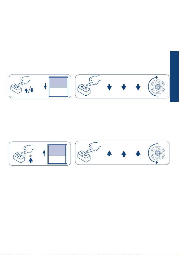
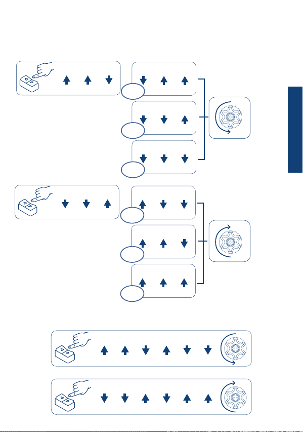
Key to symbols ....................................................................................................... p. 15
Command sequences example ............................................................................... p. 15
Limit switch setting ................................................................................................ p. 16
Procedure for limit switch setting .......................................................................... p. 16
Example 1: Setting the upper limit switch as rst position ....................................... p. 16
Example 2: Setting the lower limit switch as rst position ....................................... p. 17
Changing limit switches.......................................................................................... p. 18
Deleting of single limit switch positions ................................................................. p. 18
Deleting of all limit switch positions ...................................................................... p. 18
Activation and adjustment of the super-sensitivity ................................................. p. 19
Deactivation super-sensitivity function ................................................................... p. 19
Limit switches and obstacle detection .................................................................... p. 20
Restoring the original conguration ....................................................................... p. 20
TRANSLATION OF THE ORIGINAL INSTRUCTIONS
ENGLISH
CHERUBINI S.p.A. declares that the product is in conformity with the relevant Union
harmonisation legislation:
Directive 2014/35/EU
Directive 2014/30/EU
Directive 2011/65/EU
The full text of the EU declaration of conformity is available upon request at the
following website: www.cherubini.it.
EU DECLARATION OF CONFORMITY

13
- To prevent any danger or malfunction, the size of electrical control components
connected to the motor must be compatible with the electrical features of the motor.
- Means for disconnection must be incorporated in the xed wiring in accordance with
the national installation standards.
- The selectors inverting the direction of rotation of the motor must be provided with
mechanical interlocking.
- Invert the brown and the black conductor to change the direction of rotation.
- NEVER connect two or more selectors to the same motor.
- For outdoor use, provide the appliance with a supply cord with designation H05RN-F
containing at least 2% of carbon.
- Cable length between motor and control-switch maximal 50 m.
In case of cable length more than 50 m an interface-relay have to be used.
ELECTRICAL CONNECTIONS
1- brown (UP)
2- black (DOWN)
3- blue
4- yellow-green
ENGLISH

14
HOW TO PREPARE THE MOTOR
NB: If you use tubes with a round form, the driving pulley must be xed to the tube, and
the installation is to be paid by the person who installs the system. For other tube sections
the tting is optional, but strongly recommended.
STOP RING NUT ADAPTOR
DRIVING PULLEY
STOP RING NUT
1
2
3
1. Insert the adaptor in the stop ring nut
mating the groove with the reference notch
and push till they touch.
2. Fix the driving pulley on the motor pin
until the stop pin clicks.
3. Insert the motor fully in the rolling tube.
ENGLISH

15
KEY TO SYMBOLS
Press the up or down button to raise
the awning
Press the buttons as indicated in rapid sequence and hold the button
down at the step marked by “HOLD”, to check the motor conrmation
movement.
UP DOWN
HOLD
Press the
UP-button
Press the
DOWN-button
Press and hold
down the button
Motor
rotation to
conrm
DOWN DOWN
HOLD
UP
2 sec
2 sec
DOWN
UP
?
DOWN
UP
DOWN
UP ?
COMAND SEQUENCES EXAMPLE
Most of the command sequences have three or six distinct steps.
The buttons should be pressed quickly (<0.5 sec) as indicated in the sequence.
The time interval between each step should not be more than 1 second, otherwise the
command sequence will be cancelled.
To receive conrmation that the sequence has been accepted by the motor, the button
must be held down at the nal step marked by HOLD.
DOWN DOWN
HOLD
UP
2 sec
Command sequence example in 3 steps:
Attention! If the sequence requires a repetition of the same commands
(Up+Up/Down+Down), an interposition of the Stop position could be necessary
depending on the type of switch in use.
ENGLISH

16
LIMIT SWITCH SETTING
The motor can learn the limit switches only in manual mode.
It is suggested that the strength of the awning, its couplings and its safety lugs be checked.
As long as both of the limit switch positions have not been learned, the motor
will move briey, stop and then start back up again.
PROCEDURE FOR LIMIT SWITCH SETTING
Depending on your individual needs, it’s possible to learn rst either the upper or the
lower limit switch.
EXAMPLE 1:
SETTING THE UPPER LIMIT SWITCH AS FIRST POSITION
If the awning is already completely closed up, it must be rst opened out to
about 20 cm, then proceed as follows.
Using the button switch, bring the awning up to the desired position (for cassette-
awnings, hold the button pressed until the motor stops automatically on the closing
position).
To set the upper limit switch position perform the indicated sequence of commands
(UP-UP-UP) with the button to be linked to the ascent.
Using the button to be linked to descent bring the awning down to the desired position.
To set the lower limit switch position perform the indicated sequence of commands
(DOWN-DOWN-DOWN).
UP UP
HOLD
UP
2 sec
DOWN DOWN DOWN
HOLD
2 sec
DOWN
UP
?
DOWN
UP ?
ENGLISH

17
EXAMPLE 2:
SETTING THE LOWER LIMIT SWITCH AS FIRST POSITION
If the awning is already completely lowered, it must be rst raised about 20 cm,
then proceed as follows.
Using the button switch, bring the awning down to the desired position.
To set the lower limit switch position perform the indicated sequence of commands
(DOWN-DOWN-DOWN) with the button to be linked to descent.
Using the button to be linked to ascent bring the awning up to the desired position (for
cassette-awnings, hold the button pressed until the motor stops automatically on the
closing position).
To set the upper limit switch position perform the indicated sequence of commands
(UP-UP-UP).
DOWN DOWN DOWN
HOLD
2 sec
DOWN
UP
?
UP UP
HOLD
UP
2 sec
DOWN
UP ?
ENGLISH

18
CHANGING LIMIT SWITCHES
The following command sequences may be performed only after the limit switches have
been set and only when the motor is in one of the two limit switch positions.
DELETING OF SINGLE LIMIT SWITCH POSITIONS
DELETING OF ALL LIMIT SWITCH POSITIONS
Deletion of the UPPER limit switch.
Take the awning to the upper limit switch and perform the sequence:
Deletion of the LOWER limit switch.
Take the awning to the lower limit switch and perform the sequence:
From the UPPER position
From the LOWER position
Deleting of one or both limit switches is indicated by the motor pausing briey before
moving again until both limit switch positions have been memorised again.
PLEASE NOTE: When the limit switches are deleted, the super-sensitivity settings
are also deleted.
UP UP UP UP UPDOWN
HOLD
2 sec
UP UP UP UPDOWN DOWN
HOLD 2 sec
UPDOWN DOWN DOWN DOWN DOWN
HOLD
2 sec
UP UPDOWN DOWN DOWN DOWN
HOLD
2 sec
ENGLISH

19
DOWNUPUP
DOWN DOWN UP
DOWN UP UP
HOLD
DOWNDOWNUP
HOLD
DOWN DOWN UP
HOLD
DOWNUPUP
HOLD
DOWN DOWN DOWN
HOLD
UP UPUP
HOLD
MAX
MAX
MID
MID
MIN
MIN
From the LOWER position
From the UPPER position
To complete activation of the
super-sensitivity, run the awning
through a complete cycle of
opening and closing.
conrm
conrm
ACTIVATION AND ADJUSTMENT OF THE SUPER-SENSITIVITY
2 sec
2 sec
DEACTIVATION SUPER-SENSITIVITY FUNCTION
From the UPPER position
From the LOWER position
UP UP UPDOWN DOWNDOWN
HOLD 2 sec
UP UP UP
DOWNDOWN DOWN
HOLD
2 sec
The super-sensitivity feature for obstacles when descending may be enabled on three levels
only after both limit switches have been set.
ENGLISH

LIMIT SWITCHES AND OBSTACLE DETECTION
Obstacle detection in ASCENT
Obstacle detection in ascent is enabled only after both the limit switches have been set.
In the event of obstacle detection in ascent, the motor will stop without making any
movements backwards.
Obstacle detection in DESCENT
In the event of obstacle detection in descent, with the super-sensitivity feature on, the
motor stops and makes a backwards safety movement.
20
DOWNUP
RESTORING THE ORIGINAL CONFIGURATION
To restore the original motor conguration perform the procedure as described below:
- Connect both the brown and black motor wires under the same switch, e.g. UP.
PLEASE NOTE: recovery of the default conguration will delete the limit switches
and disabling the super-sensitivity.
- Press the UP button for at least 2 seconds.
- Disconnect and then restore the original control switch electrical connections (see
page 13).
1- Brown
2 - Black
3 - Blue
4 - Yellow-green
ENGLISH

Rev: 2 07/2018 - Cod: A4516_6D60
CHERUBINI Deutschland GmbH
Siemensstrasse, 40 - 53121 Bonn - Deutschland
Tel. +49 (0) 228 962 976 34 / 35 | Fax +49 (0) 228 962 976 36
info@cherubini-group.de | www.cherubini-group.de
CHERUBINI France S.a.r.l.
ZI Du Mas Barbet
165 Impasse Ampère
30600 Vauvert -France
Tél. +33 (0) 466 77 88 58 | Fax +33 (0) 466 77 92 32
info@cherubini.fr | www.cherubini.fr
CHERUBINI Iberia S.L.
Avda. Unión Europea 11-H
Apdo. 283 - P. I. El Castillo
03630 Sax Alicante - Spain
Tel. +34 (0) 966 967 504 | Fax +34 (0) 966 967 505
info@cherubini.es | www.cherubini.es
CHERUBINI S.p.A.
Via Adige 55
25081 Bedizzole (BS) - Italy
Tel. +39 030 6872.039 | Fax +39 030 6872.040
info@cherubini.it | www.cherubini.it
This manual suits for next models
1
Table of contents
Other CHERUBINI Window Blind manuals
Popular Window Blind manuals by other brands

FIBARO
FIBARO ROLLER SHUTTER 3 manual

HunterDouglas
HunterDouglas Silhouette Installation operation care

Silent Gliss
Silent Gliss SG 1032 installation instructions

DEZ Furnishings
DEZ Furnishings QJBK quick start guide

my home
my home Malin Assembly instructions

Silent Gliss
Silent Gliss SG 1012 installation instructions

Shade Elements
Shade Elements Omni Screen quick start guide

VENETA
VENETA 65101-50725-D How to install

SKILTEC
SKILTEC LUXAFLEX LUMINETTE Installation operation care

MHZ
MHZ R 03 Installation and operating instructions

CHILD SAFETY
CHILD SAFETY arzion outdoor Mounting instruction

MHZ
MHZ 11-8110 Installation and operation instruction