Cheval ARION 600W Series User manual
(International Version) AAG.20.03.002


ARION : 600 SERIES - Safety Information
This assembly guide applies to the following ARION Enclosure: 600 Series
PREFACE:
This assembly guide is provided to prevent service personnel from committing an act that results in the risk of re, electric shock, or injury to persons. The equipment shall be
installed or serviced by trained service personnel in accordance with the applicable requirements of the National Electrical Code, NFPA 70-1999 or Canadian Electrical Code and
the applicable sections of ANSI C2, the National Electrical Safety Code. Not following these instructions could result in the risk of re, electric shock, or injury to persons.
SAFETY SYMBOLS USED IN THIS MANUAL
This assembly guide provides general safety guidelines to be observed during installation, operation, and maintenance of the ARION Enclosure.
SAFETY CONSIDERATIONS
• When applicable, rack systems are not intended as enclosures and do not provide any degree or protection as that of an enclosure.
• Only UL Listed ITE (Information Technology Equipment) units should be installed inside the ARION Enclosure.
• Be sure to read and follow all individual manufacturer equipment manuals for safety and installation instructions.
• Proper spacing is required when installing electrical equipment to avoid electrical shock. Maintain minimum spacing between the accessories and components and the
computer enclosure assembly for safe operation of the equipment when installed in accordance with the specication.
R
WARNING: Improper handling and use of the ARION Enclosure could result in equipment damage, serious injury, or possible death.
WARNING:
• Only indentical ARION enclosures should be installed together when ganging.
• The ambient temperature operating range for the ARION Enclosure and accessories is +50 to +95˚F (+10 to +35˚C).
• The non-operating temperature is -4 to +140˚F (-20 to +60˚C).
• Once in place at the desired/intended location, deploy the leveling feet for maximum stability.
• If stabilizing brackets are used, they must be tightened until they are ush to the frame.
• Rated or maximum load capacity for the ARION Enclosure is 1,400 kilograms on the oor or on leveling glides.
• No EIA slide rail location instructions are provided here, location is determined by end user.
• To maintain a uniform distribution of the mechanical load in the ARION Enclosure, load the heaviest equipment rst, at the bottom of the ARION Enclosure and load the
lighter unit at the top.
WARNING: Only install equipment after the ARION Enclosure has been property secured. If you need to move the enclosure after equipment installation, exercise extreme
caution to avoid the enclosure tipping over. The casters are rated to about 650 lbs each dynamic load. Moving a fully loaded cabinet will generate heat which can damage
the casters. To avoid overheating, move the enclosure a maximum of 100 yards, then stop for 2 minutes and allow the casters to cool down. Repeat until nal location
is reached.
WARNING: Be careful when moving enclosures before installation. Sudden stops and starts, excessive force, obstructed routes, and uneven oor surfaces may cause the
enclosure to topple over.
LOADING EQUIPMENT:
WARNING : Failure to follow directions in the warning could result in injury to persons or loss of life.
TIP : Indicates a recommended way of working.

Unpacking Instructions
Parts list
Tools & Hardware
Frame Structure Assembly
Middle Side Brace Assembly
Leveling Feet and Caster Assembly
Top Panel Assembly
PDU/Vertical Cable Rail Assembly
PMA (19”Mounting Rails) Set Assembly
Door Hinges & Door Latch Bracket Assembly
Front Door (Curve) Assembly
Rear Door (Split) Assembly
Side Panel Assembly
Grounding the 19”Enclosure
Product Information
About us
1
4
5
6
7
8
9
10
11
12
13
14
15
17
18
19
ARION : 600 SERIES - Table of Contents

ARION : 600 SERIES - Receiving and Unpacking Instructions
WARNING
Receiving and Initial Inspection: Although we have taken our best precautions to pack your Arion rack, damage may occur from external forces during shipment of your
Arion rack, please follow these steps.
1. Inspect the package for any indentations, holes or other damage and note these issues on the shipping documents. If possible, photograph the damaged area as well.
2. After opening the crate, check the components for any signs of damage. Record any damage and report to our customer service at: commce@chevalgrp.com. Keep the original packing materials
in case the shipping company needs to see.
3. All damages must be reported to Cheval within three (3) days after delivery. Claims made after 3 days will not be under Cheval's responsibility.
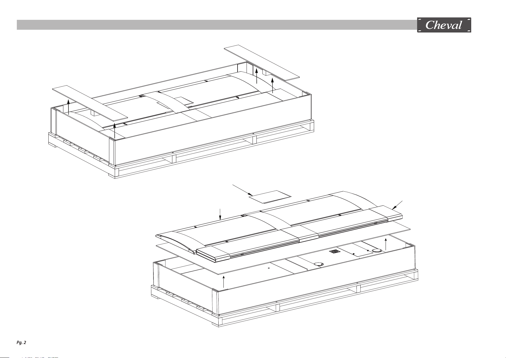
MOVING THE CARTON
HEAVY LOAD HAZARD: This carton is not intended to be lifted or moved by hand. Failure to follow these instructions can result in injury. The recommended equipment for moving the
carton are pallet jack or forklift.
1. Move the carton to a solid, level area clear of obstructions.
2. Carefully cut the wrapping straps securing the carton.
3. Remove the top cover and take out the assembly guide for further instructions.
UNPACKING AND STAGING THE COMPONENTS FOR ASSEMBLY: The Arion Enclosure has been packed to protect the components from damage during shipping.
For the best assembly experience, please follow these steps.
1. Prepare your work area. The area needed is approximately 8’ x 8’. The surface must be clean, at and either carpeted or use a drop cloth to prevent scratching the components.
2. Remove the components and check all are complete by referring to the“parts check list”. Arrange the components according the assembly sequence, Step1, Step2 and etc.
You may nd it easier to assemble steps 1-4 on a table or raised surface.
3. After step 4, stand the rack up on the oor and continue the assembly.
1030 mm.
2075 mm.
395 mm.
Thank you for purchasing our Arion 19" enclosure. We hope you nd the product experience completely to your satisfaction and appreciate any feedback you may have.
Assembly Guide
Front Door (Curve)
(P14)
Rear Door (split) kit
(P16)
ARION : 600 SERIES - Unpacking Instructions

Side Panel (P17) x 4
Assembly Hardware Bag Set
(A,B,C,D)
(A) (B)
(C) (D)
Tools Assembly Bag
Hardware Bag (P18)
PMA (P10) x 2
(P11) x 2
Vertical Post (P2) x 4
Top Panel (P6)
Caster kit (P7) x 4
Side Brace (Mid) (P4) x 2
PDU/Vertical Cable Rail (P8) x 2 Frame (Top) (P3)
Frame (Bottom) (P1)
ARION : 600 SERIES - Unpacking Instructions

Part NameItem
Check QTY
Check Item Part Name QTY
P1
P2
P3
P4
P5
P6
P7
P8
P9
Frame (Bottom)
Vertical Post
Frame (Top)
Side Brace (Mid)
Top Panel Bracket
Top Panel Assy.
Caster kit
PDU / Vertical Cable Rail Assy.
PMA Mounting Bracket
1
4
1
2
2
1
4
2
12
P10
P11
P12
P13
P14
P15
P16
P17
P18
PMA Assy (LH)
PMA Assy (RH)
Door Hinges
Door Latch Bracket
Front Door (Curve) Assy.
Split Door Latch Bracket
Rear Door (Split) Kit Assy.
Side Panel Assy.
Hardware Bag.
2
2
6
1
1
2
2
4
1
ARION : 600 SERIES - Parts List

Tools Recommended for Assembly
Assembly Hardware Set List
ARION : 600 SERIES - Tools & Hardware

ARION : 600 SERIES - Frame Structure Assembly
Tools:
- Hexagon Socket No.24 (16mm.)
- Screwdriver Torx T30
Installing Direction Locate
Step 1
Step 2
Step 2
Step 1
P2 Cross Section
STEP 1
Parts: P1 x 1, P2 x 4, P3 x 1
Hardware Set: “A”
H1 (8 pcs.)
H2 (8 pcs.)
H9 (8 pcs.)
H5 (8 pcs.)
Hand tight only
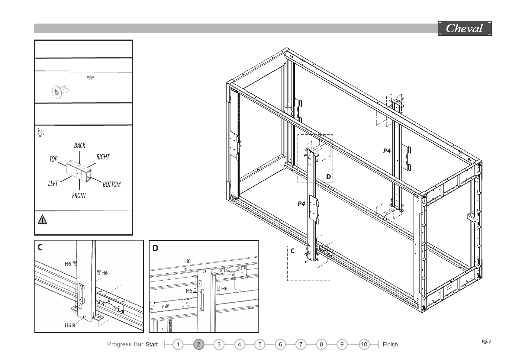
ARION : 600 SERIES - Middle Side Brace Assembly
STEP 2
Parts: P4 x 2
Hardware Set: “B”
H6 (12 pcs.)
Tools:
- Screwdriver Torx T30
Installing Direction Locate
Tighten all location
securely
G
ARION : 600 SERIES - Middle Side Brace Assembly
Leveling feet adjust follow
“G” picture
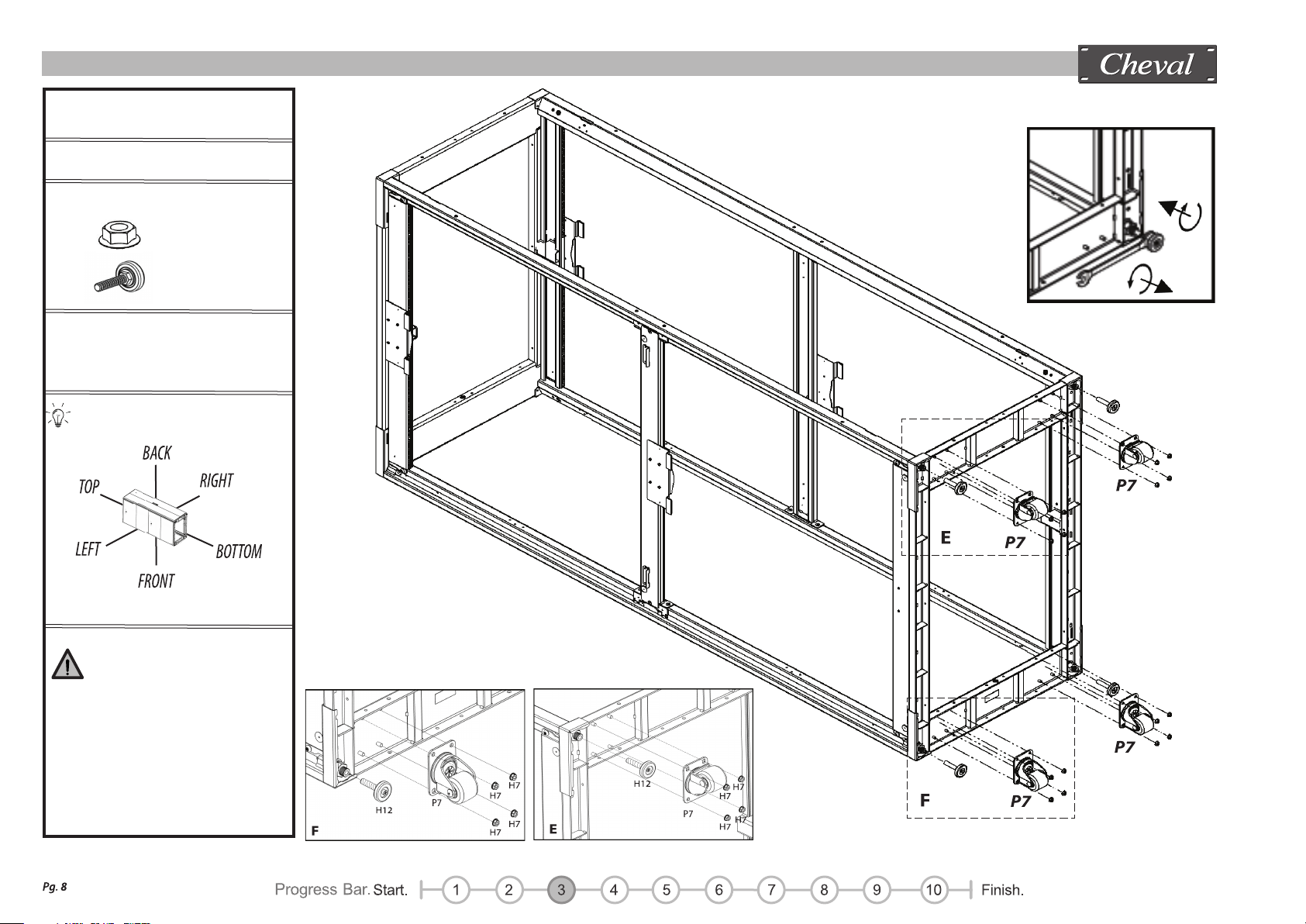
ARION : 600 SERIES - Leveling Feet And Caster Assembly
STEP 3
Parts: P7 x 4
Hardware Set: “B”
H7 (16 pcs.)
H12 (4 pcs.)
Tools:
- Hexgon Socket No. 10
- Open End Wrench No. 14
Installing Direction Locate
Once in place at the desired
location, deploy the leveling
feet for maximum stability.
The rack should not be left
standing on the casters.

(Insert Top panel tabs into frame slots.)
Hexagon Socket No.10
Make sure the Top Panel is
installed correctly before
tightening Top panel xing. (P5)
ARION : 600 SERIES - Top Panel Assembly
i
i3 Inside
i
i1
i2
STEP 4
Parts: P5 x 2, P6 x 1
Hardware Set: “C”
H5 (2 pcs.)
H7 (2 pcs.)
Tools:
- Screwdriver Torx T30
Installing Direction Locate
(Inside)
(Inside)
(Inside)
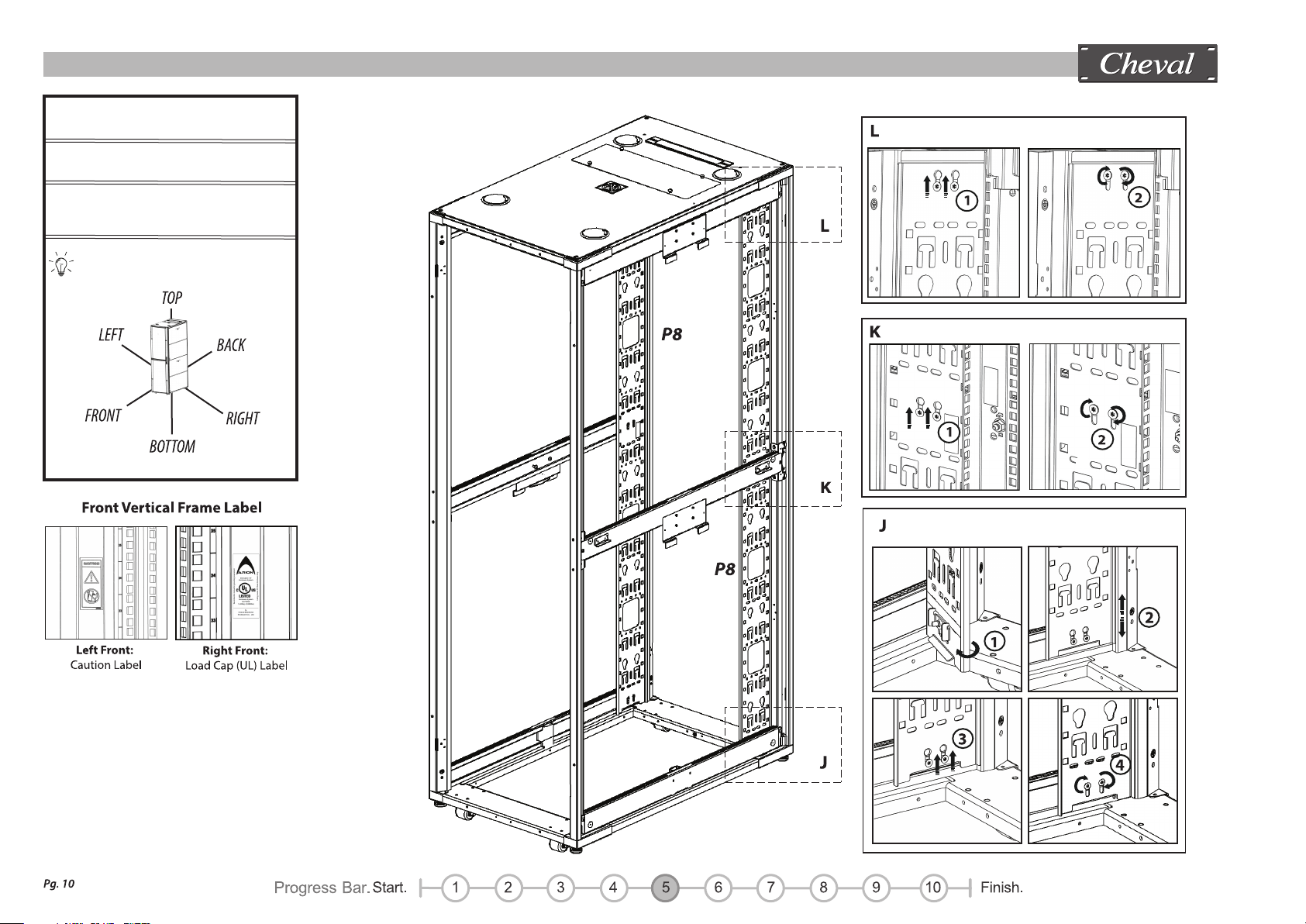
ARION : 600 SERIES - PDU / Vertical Cable Rail Assembly
STEP 5
Parts: P8 x 2
Tools:
- Screwdriver Torx T30
Installing Direction Locate

P10, P11
Cross Section
(Inside)
(Inside)
(Inside)
(Inside)
ARION : 600 SERIES - PMA 19” Mounting Rails Set Assembly
P10
N
Depth indicator
STEP 6
Parts: P9 x12, P10 x 2, P11 x 2
Hardware Set: “C”
H8 (12 pcs.)
H4 (12 pcs.)
Tools:
- Hexagon Socket No. 13
Picture 1:
Picture 2:
Use depth indicator label (”N”)
to select location and align
L/R rails.
Installing Direction Locate

H5
H6
H6
H6
H6
H6
H6
ARION : 600 SERIES - Door Hinges & Door Latch Bracket Assembly
STEP 7
Parts: P12 x 6, P13 x 1, P15 x 2
Hardware Set: “D”
H5 (6 pcs.)
H6 (6 pcs.)
Tools:
- Screwdriver Torx T30
Picture 1:
Picture 2:
Check Installing Direction
carefully for clarify
Installing Direction Locate
S
T
S
T
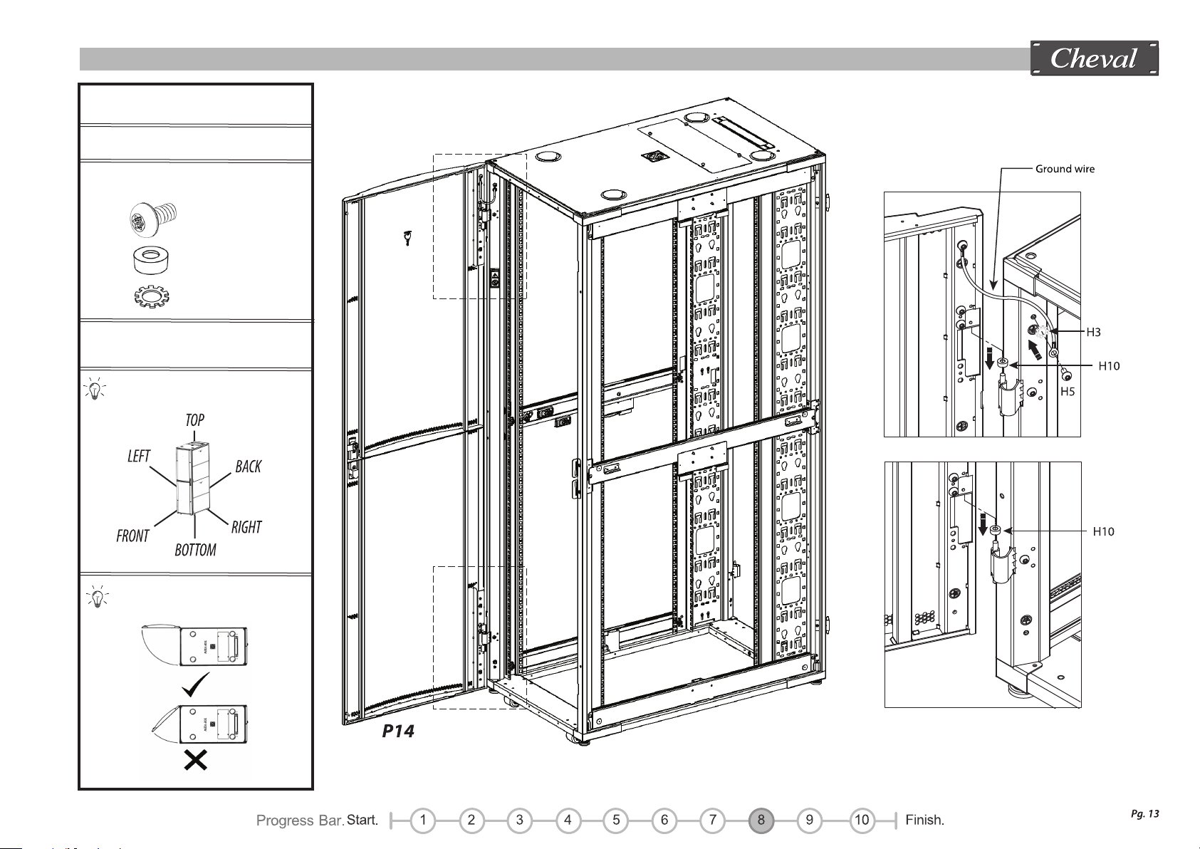
ARION : 600 SERIES - Front Door Assembly
STEP 8
Parts: P14 x 1
Hardware Set: “D”
H5 (1 pcs.)
H10 (2 pcs.)
H3 (1 pcs.)
Tools:
- Screwdriver Torx T30
Install from 90 degree angle
Installing Direction Locate

U
U
V
V
ARION : 600 SERIES - Rear Door Assembly
STEP 9
Parts: P16 x 2
Hardware Set: “D”
H5 (2 pcs.)
H10 (4 pcs.)
Tools:
- Screwdriver Torx T30
Install from 90 degree angle
Installing Direction Locate
H3 (2 pcs.)
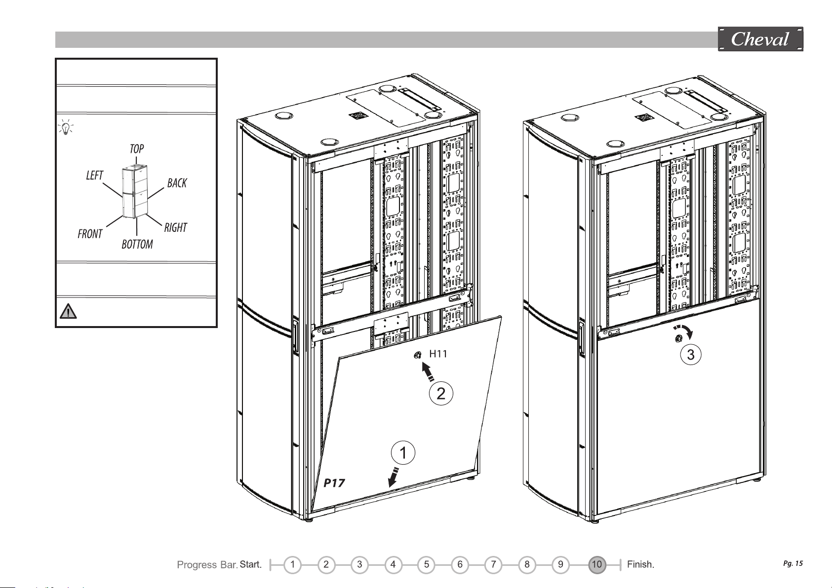
ARION : 600 SERIES - Side Panel Assembly
STEP 10 - 1
Parts: P17 x 2
Installation Step
1 > 2 > 3
Ensure lock is engaged to
prevent side panel falling o.
Installing Direction Locate

ARION : 600 SERIES - Side Panel Assembly
STEP 10 - 2
Parts: P17 x 2
Installation Step
1 > 2 > 3
Ensure lock is engaged to
prevent side panel falling o.
Installing Direction Locate
Table of contents
Popular Enclosure manuals by other brands


Panamax
Panamax MIW-POWERKIT-TL installation instructions

Huawei
Huawei OptiX OSN 9800 U32 Enhanced Subrack V100 Quick installation guide

Laney
Laney LV412A instructions

Displays2go
Displays2go JTCPCS16D Assembly instructions

StarTech.com
StarTech.com S2510BU3ISO user manual

Thermaltake
Thermaltake V3 BlacX Edition VL800M Series user manual


