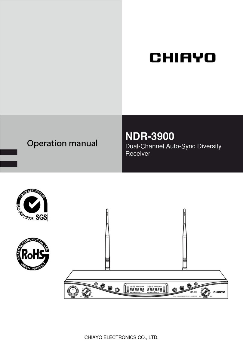
Chiayo SDR-5900 User manual

CHIAYO ELECTRONICS CO., LTD.
Operation manual
SDR-5900
Dual-Channel 2-Way Sync True
Diversity Receiver

1
SDR-5900 Dual-Channel 2-Way Sync True Diversity Receiver
Important safety instructions
◼READ, KEEP and HEED these instructions.
◼CLEAN ONLY with dry cloth.
◼DO NOT block any ventilation openings. Allow sufficient distances for adequate ventilation
and install in accordance with the manufacturer’s instructions.
◼DO NOT install or place near any heat sources such as open flames, radiators, heat registers,
stoves, or other apparatus (including amplifiers) that produce heat.
◼DO NOT defeat the safety purpose of the polarized or grounding type plug. A polarized plug
has two blades with one wider than the other. A grounding type plug has two blades and a
third grounding prong. The wider blade or the third prong are provided for your safety. If the
provided plug does not fit into your outlet, consult an electrician for replacement of the
obsolete outlet.
◼PROTECT the power cord from being walked on or pinched, particularly at plugs,
convenience receptacles, and the point where they exit from the apparatus.
◼ONLY USE attachments/accessories specified by the manufacturer.
◼USE only with a cart, stand, tripod, bracket, or table specified by the manufacturer, or sold
with the apparatus. When a cart is used, use caution when moving the cart/apparatus
combination to avoid injury from tip-over.
◼UNPLUG this apparatus during lightning storms or when unused for long periods of time.
◼REFER all servicing to qualified service personnel. Servicing is required when the apparatus
has been damaged in any way, such as power supply cord or plug is damaged, liquid has
been spilled or objects have fallen into the apparatus, the apparatus has been exposed to rain
or moisture, or does not operate normally.
◼To reduce the risk of fire or electric shock, DO NOT expose this apparatus to rain or moisture.
◼DO NOT attempt to modify this product. Doing so could result in personal injury and/or
product failure.
2
Instructions
Thank you for choosing CHIAYO wireless microphone system!
For more details, please take a few moments to read this operating manual for thorough
understanding of the function and operation of both transmitter and receiver.
In the box
SDR-5900 receiver
2 handheld / beltpack transmitters
(optional)
a pair of antennas
audio cable
switching adaptor
(plug varies from country to country)
rackmount kit:
short bracket (12R1007) *2
screw (14A2129) *8
(Refer to P.4)
operation manual
**The above specifications are subject to change without prior notice.
Optional related products
▍Transmitters
SQ-6100 IrDA
Handheld microphone
SM-7100 IrDA
Belt-pack transmitter
SQ-5100 IrDA
Handheld microphone
SM-6100 IrDA
Belt-pack transmitter
▍Antennas
DA-80
UHF directional antenna
RA-80
UHF Remote antenna
▍Antenna booster
AB-80
UHF Antenna Booster
▍Antenna dividers
AD-85
Wideband 4-Channel Antenna Divider
PAD-70
Wideband 4-Channel Powered Antenna
Divider
S
D
R
-
590
0
UH
F雙頻
道數位鎖
定
自動
對
頻自動
選
訊無線麥克風
系
統

3
SDR-5900 Dual-Channel 2-Way Sync True Diversity Receiver
Antenna A
(TNC type)
Parts and functions
Important
1.Please make sure that the output DC voltage range of the switching power covers that
specified by the receiver before turning it on.
2.The RF signal meter bars and diversity A/B antenna indicator will appear to denote RF signal
received after turning on the transmitter.
3.The receiver and transmitter must be the same frequency.
4.While using the transmitter, the audio signal meter bars will appear to denote audio signal
received.
FRE Q SQ
R F A F
MHz
C H BA
MENUMENU
ENTERENTER SYNCSYNC MAXMINMIN FREQ S Q
R F A F
MHz
C H BA
MENUMENU
ENTERENTER SYNCSYNC MAXMINMIN
POW E RPOW E R
TRUE DIVERSITY RECEIVERTRUE DIVERSITY RECEIVER
SDR-5900SDR-5900
ANT. B MIC 2 OUT
1.G
2.
3.
MIXED OUT
MIC LINE
MIC 1 OUT
1.G
2.
3.
DC IN
12V
ANT. A
SQ
RF AF
MHz
BA
650.250
C H 00 2
FREQ
CH-1
UP▲
DOWN▼
CH-1
IR sensor
IrDA sync
CH-1
Volume control
CH-2
UP▲
DOWN▼
CH-2
IR sensor
IrDA sync
CH-2
Volume control
Power switch
CH-1 LCD
CH-1
MENU
ENTER
CH-2 LCD
CH-2
MENU
ENTER
Antenna B
(TNC type)
Mixed MIC/LINE audio
output impedance switch
DC input
CH-2
balanced audio output
Mixed unbalanced audio output
CH-1
balanced audio output
Channel
Diversity A/B antenna
RF signal meter
Audio signal meter
Frequency
Transmitter battery power

4
Instructions
Receiver installation
1. The receiver should be at least 1m above the ground and 1m away from a wall or metal
surface to minimize reflections.
2. The transmitter should also be at least 1m away from a wall or metal surface to minimize
reflections.
3. The transmitter should also be at least 1m away from the receiver. Keep antennas away from
noise source such as motors, automobiles, neon light as well as large metal objects.
4. Power voltage should not below 12V DC or above 15V DC. Deficient current causes unstable
operating voltage or malfunction and over current shortens the product life and possibly
damages circuits.
Rack mounting
The receiver can be cabinet-mounted with accompanied kit as illustrated below.
1m 1m
1m

5
SDR-5900 Dual-Channel 2-Way Sync True Diversity Receiver
Channel synchronizing between receiver and transmitter
Align infrared areas of the receiver and transmitter within 10~30cm.
Changing the receiver’s channel
1 Press the synchronizing button of the
transmitter.
2 The transmitter's LED will glow to denote
synchronizing signal transmitted.
3 The channel/frequency of the receiver will
change and then the synchronization is
complete.
Changing the transmitter’s channel
1 Press the SYNC button of the receiver
2 The receiver’s LCD will show to
denote synchronizing signal being sent.
3 The channel/frequency of the transmitter will
change and then the synchronization is
complete.
If it doesn’t work check that you have the IR sensor panels aligned, that they are facing each
other, devices are within 10~30cm of each other, and try again.
FRE Q SQ
RF AF
MHz
C H BA
MENUMENU
ENTERENTER SYNCSYNC MAXMINMIN
FRE Q SQ
RF AF
MHz
C H BA
MENUMENU
ENTERENTER SYNCSYNC MAXMINMIN
10~30cm

6
Instructions
Channel scanning
For an interference- free operation, a cleaner channel might be necessary if the current one
receives too much interference. To operate the scanning:
1 Press MENU button to make the frequency icon appear on the bottom.
2 Press ENTER button until this icon flashes to denote readiness for setting.
3 Press ▲(up) or ▼(down) button to find and locate a clear, interference- free channel.
4 After a channel is chosen, press ENTER button or wait 5 seconds to store the setting
and the channel will not change after reboot until the setting is changed again.
FREQ S Q
RF AF
MHz
C H BA
MENUMENU
ENTERENTER SYNCSYNC MAXMINMIN
RF AF
MHz
BA
650.250
C H 002
FREQ
FREQ S Q
RF AF
MHz
C H BA
MENUMENU
ENTERENTER SYNCSYNC MAXMINMIN
RF AF
MHz
BA
650.250
C H 002
FREQ
FREQ S Q
RF AF
MHz
C H BA
MENUMENU
ENTERENTER SYNCSYNC MAXMINMIN
FREQ
RF AF
MHz
BA
652.000
C H 009
FREQ S Q
RF AF
MHz
C H BA
MENUMENU
ENTERENTER SYNCSYNC MAXMINMIN
FREQ
RF AF
MHz
BA
652.000
C H 009

7
SDR-5900 Dual-Channel 2-Way Sync True Diversity Receiver
Squelch (SQ) setting
You may adjust the SQUELCH (SQ) when strong RF interference is encountered.
When the transmitter is turned off but the receiver still has audio output, it is apparent that there
is RF interference. At this time, just increase the SQ level to make the receiver filter out
background noise when receiving it. However, the receiving distance will be shortened as the
SQ level increases. Therefore, maximum receiving distance should be considered when
adjusting the SQ level to eliminate noise.
1 Press MENU button to go to the squelch setting page.
2 Press ENTER button until this icon flashes to denote readiness for setting.
3 Press ▲(up) or ▼(down) button to select a new squelch (sensitivity) level between 01
and 10. The default level is 01.
4 After a squelch (sensitivity) level is chosen, press ENTER button or wait 5 seconds to
store the setting and the level will not change after reboot until the setting is changed
again.
FREQ S Q
RF AF
MHz
C H BA
MENUMENU
ENTERENTER SYNCSYNC MAXMINMIN
SQ
LE-02
FREQ S Q
RF AF
MHz
C H BA
MENUMENU
ENTERENTER SYNCSYNC MAXMINMIN
SQ
LE-02
FREQ S Q
RF AF
MHz
C H BA
MENUMENU
ENTERENTER SYNCSYNC MAXMINMIN
SQ
LE-06
FREQ S Q
RF AF
MHz
C H BA
MENUMENU
ENTERENTER SYNCSYNC MAXMINMIN
SQ
LE-06

8
Instructions
Audio output connection
◼Mixed unbalanced audio output
1. ¼” (6.3mm) PHONE PLUG connector provides unbalanced audio output signal from this
jack to the mixer/amplifier. Use an audio output cable with ¼” (6.3mm) PHONE PLUG
connectors. Connect one end from the unbalanced output jack of the receiver, and the
other end to the “LINE IN” or “MIC IN”jack of the mixer/ amplifier.
2. Level switch setting
(1).When connecting to the LINE /AUX IN of
a mixer/amplifier, switch to “LINE”
position. DO NOT use the “MIC” position
as they may not deliver a sufficient high
output level.
(2).When connecting to the “MIC IN” jack of a
mixer/amplifier, switch to “MIC” position.
Overload distortion may occur at the
wrong level position.
SDR-5900 amplifier
SDR-5900 amplifier
◼Individual balanced audio output
XLR connector provides balanced audio output signal from this jack to the mixer/amplifier.
Use an audio output cable with “XLR” or “Cannon” connector, connect one end to the
balanced output jack of the receiver, and the other end to the “MIC IN” jack of the mixer/
amplifier.
ANT. B MIC 2 OUT
1.G
2.
3.
MIXED OUT
MI C L IN E
MIC 1 OUT
1.G
2.
3.
DC IN
12 V
ANT. A
MIXED OUT
MIC LINE
LINE 1 LINE 2
MIXED OUT
MIC LINE
MIC 1 MIC 2
ANT. B MIC 2 OUT
1.G
2.
3.
MIXED OUT
MI C L IN E
MIC 1 OUT
1.G
2.
3.
DC IN
12 V
ANT. A
Mixer
▼
◄Amplifier

9
SDR-5900 Dual-Channel 2-Way Sync True Diversity Receiver
FAQ & useful operation tips
1 What are the common causes of dropouts?
⚫Improper installation of the antenna (wrong antenna frequency band, unlocked
antenna, blocked antenna position, etc.)
⚫Environmental interference (Please switch to another channel when interference
occurs.)
⚫Interference from the surrounding audio equipment (We recommend to adjust the
position of the receiver at this moment.)
⚫Choose true-diversity models.
2 What is the SQUELCH (SQ)? What is it for?
The SQUELCH (SQ) control is on the rear panel of the receiver or SQUELCH
SETUP in the control page of LCD display, and its level has been set up. You may
adjust it when strong RF interference is encountered.
When the transmitter is turned off but the receiver still has audio output, it is apparent
that there is RF interference. At this time, just increase the SQ level to make the
receiver filter out background noise when receiving it. However, the receiving
distance will be shortened as the SQ level increases. Therefore, maximum receiving
distance should be considered when adjusting the SQ level to eliminate noise.
3 What is IrDA? What is it for?
IrDA is the abbreviation of Infrared Data Association. It is a standard for the
equipment which use infrared for short-distance transmission. (i.e. computers, PDAs
and mobile phones) CHIAYO is the first company to apply this technology to wireless
microphone products.
The biggest advantage of CHIAYO's IrDA technology is bidirectional data
transmission between receiver and transmitter, with a click on the transmitter to
synchrozize the receiver and vise versa. It is different from most unidirectional
models seen on the market.
4 Why does the battery life become shorter, even less than two hours, after new
batteries installed into the microphone (transmitter)?
Please make sure the installed battery type corresponds to the setting. Set NiMH
batteries to "NiMH" and non-rechargeable batteries to "AKLN". Short operating time
should be related to the quality of the battery. When purchasing batteries, please first
consider well-known brands such as: TOSHIBA, DURACELL, SONY, etc.
5 Why does the microphone (transmitter) overheat after installing new batteries?
It should be related to the quality of the battery. The battery itself might have had short-
circuit problem. When purchasing batteries, please first consider well-known brands
such as: TOSHIBA, DURACELL, SONY, etc.

CHIAYO ELECTRONICS CO., LTD.
Http://www.chiayo.com.tw|Email: sales@chiayo.com.tw
Office: 30, Lane 27, Section 4, Jen-Ai Road, Taipei 10685, Taiwan
Tel: 886-2-27415741|Fax: 886-2-27525242
Factory: 88, Chung-Hsiao Street 2, Chiayi 60080, Taiwan
Tel: 886-5-2711000|Fax: 886-5-5767611
Other manuals for SDR-5900
2
Other Chiayo Receiver manuals

Chiayo
Chiayo SDR-6220 User manual

Chiayo
Chiayo NDR-2110 User manual

Chiayo
Chiayo SDR-5100M Installation manual

Chiayo
Chiayo NDR-3120 Installation manual

Chiayo
Chiayo SDR-5200M IrDA User manual

Chiayo
Chiayo DWR-2420 User manual

Chiayo
Chiayo NDR-3110 User manual

Chiayo
Chiayo QR-4000N User manual

Chiayo
Chiayo DWR-2410 User manual

Chiayo
Chiayo NDR-2120 User manual