Chiayo SDR-6220 User manual

Operation manual
CHIAYO ELECTRONICS CO., LTD.
SDR-6220
SDR-6120
UHF Dual-Channel 2-Way Sync
True Diversity / Diversity Receiver
CH
FREQSQ
RF AF
AB
0 0 1
630000
VOL
CH
FREQSQ
RF AF
AB
0 0 1
630000
VOL
SDR-6120
Wireless Receiver SET SYNCSET SYNC

1
SDR-6220/6120 UHF Dual-Channel 2-Way Sync True Diversity Receiver
Thank you for choosing this wireless microphone system! For more details, please take a few
moments to read this operating manual to have a thorough understanding of the function and
operation of both transmitter and receiver.
In the box
SDR-6220 / 6120 receiver
two transmitters
(handheld / belt-pack)
a pair of antennas
audio cable
switching adaptor
operation manual
** Remark: The above specifications are subject to change without prior notice.
Important
1.Please make sure that the output DC voltage range of the switching power covers that
specified by the receiver before turning it on.
2.The RF meter bars and antenna diversity indicator will appear to denote RF signal received
after turning on the transmitter.
3.The receiver and transmitter must be the same frequency.
4.While using the transmitter, the audio meter bars will appear to denote audio signal received.
RF meter Antenna selection Transmitter battery
Channel/frequency Audio meter
CH
FREQSQ
RF AF
A B
0 0 1
630000
VOL
CH
FREQSQ
RF AF
A B
0 0 1
630000
VOL
SDR-6120
Wire less R eceiv er SE T SY N CSE T SY N C
CH
FREQSQ
RF AF
A B
0 0 1
63 0000
VOL

2
Instructions
Parts and functions
Power switch LCD
Function settings on the receiver
VOLUME adjusting
Volume level can be adjusted by the UP(▲) and DOWN(▲) buttons, from VOL 00 to VOL 15.
CH
FREQSQ
RF AF
A B
0 0 1
63 0000
VOL
CH
FREQSQ
RF AF
A B
0 0 1
63 0000
VOL
SDR-6120
WirelessReceiver SET SYNCSET SYNC
AN T. ADC IN
12V
1.G
2.
3.
1.G
2.
3.
BALANCED OUT 2ANT.B BALANCED OUT 1OUTPUT 2 OUTPUT 1LEVEL
MIC LINE MIXED SEPARATE
OUTPUT MODE
SET SYNC
VOL
VOL 12
IrDA synchronization button
SET button
IR sensor area
UP button
DOWN button
Antenna A (TNC)
DC input
CH-1
unbalanced audio output
CH-1
balanced audio output
Mixed audio output switch
MIC/LINE output impedance switch,
only for unbalanced audio output.
CH-2
unbalanced audio output
CH-2
balanced audio output
Antenna B (TNC)
CH 1
CH 2

3
SDR-6220/6120 UHF Dual-Channel 2-Way Sync True Diversity Receiver
CHANNEL scanning
For an interference- free operation, a cleaner channel might be necessary if the current one
receives too much interference. To operate the scanning:
1 Press SET button to make the frequency icon appear on the bottom.
2 Press UP(▲) and DOWN(▲) button to find and locate a clear, interference- free
channel.
3 After a channel is chosen, press SET button or wait 3 seconds to save the setting.
Channel synchronizing between receiver and transmitter
Align infrared areas of the receiver and transmitter within 10~30cm.
FREQ
SET SYNC
CH
FREQ
RF
0 0 2
650.250
SET SYNC
CH
FREQ
RF
0 0 9
652.500
SET SYNC
CH
FREQ
RF
0 0 9
652.500

4
Instructions
Changing the receiver’s channel
1 Press the synchronizing button of the
transmitter.
2 The transmitter's LED will grow to denote
synchronizing signal transmitted.
3 The channel/frequency of the receiver will
change and then the synchronization is
complete.
Changing the transmitter’s channel
1 Press the SYNC button of the receiver
2 The receiver’s LCD will show to
denote synchronizing signal being sent.
3 The channel/frequency of the transmitter will
change and then the synchronization is
complete.
If it doesn’t work check that you have the IR sensor panels aligned, that they are facing each
other, devices are within 10~30cm of each other, and try again.
SQUELCH (SQ) adjusting
When interference is encountered try reducing the sensitivity of the receiver, thus less
susceptible to interference. To operate the squelch setting:
1 Press SET button to turn to the squelch setting page and the LCD will display current
squelch level (LE-02).
2 Press UP(▲) and DOWN(▲) button to select a new squelch (sensitivity) level between
1 and 10.
3 After a squelch (sensitivity) level is chosen, press SET button or wait 3 seconds to
store the setting.
Since increasing the squelch level will also reduce the reception distance, it’s recommended to
choose the lowest level that can eliminate the interference.
CH
FREQSQ
RF AF
AB
00 1
630000
VOL
CH
FREQSQ
RF AF
AB
0 0 1
630000
VOL
SDR-6120
Wireless Receiver SET SYNCSET SYNC
SET SYNC
SQ
LE-02
SET SYNC
SQ
LE-06
SET SYNC
SQ
LE-06

5
SDR-6220/6120 UHF Dual-Channel 2-Way Sync True Diversity Receiver
If this still does not solve the problem it means this frequency is not suitable. Adjust the squelch
back to its preset level and use the scan function to locate a clear, interference-free channel.
BUTTON LOCK & UNLOCK
1 Press SET button to turn to the BUTTON LOCK page and the LCD will display current
lock status (L-OFF).
2 Press UP(▲) and DOWN(▲) button to switch between L-OFF (unlocked) and L-ON
(locked). The UP(▲) and DOWN(▲) buttons don’t function under L-ON status.
3 After a locking status is chosen, press SET button or wait 3 seconds to store the
setting.
Rack mounting
The receiver can be cabinet-mounted by either one or two units. If only one receiver is to be
mounted, an optional kit is available and it's installed as shown in Fig 1. If two receivers are to
be mounted, they can be assembled by another kit and installed as shown in Fig 2.
Fig 1. Rack mount of one receiver
Fig 2. Rack mount of two receivers
SET SYNC
L-OFF
SET SYNC
L-ON
SET SYNC
L-ON

6
Instructions
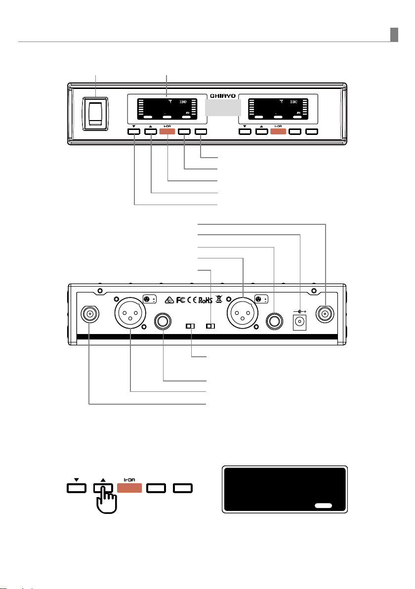
Audio output connection
Balanced output: XLR connector provides balanced audio output signal from this jack to the
mixer/amplifier. Use an audio output cable with “XLR” or “Cannon” connector, connect one
end to the balanced output jack of the receiver, and the other end to the “MIC IN” jack of the
mixer/ amplifier.
①MIC IN + Separate
②MIC IN + Mixed
Level ▼
Mode ▼
Level ▼
Mode ▼
MIC
SEPARATE
MIC
MIXED
Unbalanced output: ¼” PHONE PLUG connector provides unbalanced audio output signal
from this jack to the mixer/amplifier. Use an audio output cable with ¼ ” PHONE PLUG
connectors. Connect one end from the unbalanced output jack of the receiver, and the other
end to the “LINE IN” or “MIC IN”jack of the mixer/ amplifier.
Level switch setting: When connecting to the LINE /AUX IN of a mixer/amplifier, switch to
“LINE” position. DO NOT use the “MIC” position as they may not deliver a sufficient high
output level. When connecting to the “MIC IN” jack of a mixer/amplifier, switch to “MIC”
position. Overload distortion may occur at the wrong level position.
①LINE IN + Separate
②LINE IN + Mixed
③MIC IN + Separate
④MIC IN + Mixed
LINE/AUX IN
LINE/AUX IN
MIC IN
MIC IN
Level ▼
Mode ▼
Level ▼
Mode ▼
Level ▼
Mode ▼
Level ▼
Mode ▼
LINE
SEPARATE
LINE
MIXED
MIC
SEPARATE
MIC
MIXED
AN T. ADC I N
12V
1.G
2.
3.
1.G
2.
3.
BALA NCE D OUT 2ANT. B BALA NCE D OUT 1OUTP UT 2 OUTP UT 1LEVE L
MIC LINE MIXED SEPARATE
OUTP UT MO DE
AN T. ADC I N
12V
1.G
2.
3.
1.G
2.
3.
BALA NCE D OUT 2ANT. B BALA NCE D OUT 1OUTP UT 2 OUT PUT 1LEVE L
MIC LINE MIXED SEPARATE
OUTP UT MO DE
MIC LINE
LEVEL
MIXED SEPARATE
OUTPUT MODE
MIC LINE
LEVEL
MIXED SEPARATE
OUTPUT MODE
AN T. ADC IN
12V
1.G
2.
3.
1.G
2.
3.
BALA NCE D OUT 2ANT.B BALA NCE D OUT 1OUTP UT 2 OUTP UT 1LEVE L
MIC LINE MIXED SEPARATE
OUTP UT MO DE
AN T. ADC IN
12V
1.G
2.
3.
1.G
2.
3.
BALA NCE D OUT 2ANT.B BAL ANCE D OUT 1OUT PUT 2 OUT PUT 1LEV EL
MIC LINE MIXED SEPARATE
OUTP UT MO DE
AN T. ADC IN
12V
1.G
2.
3.
1.G
2.
3.
BALA NCE D OUT 2ANT.B BALA NCE D OUT 1OUTP UT 2 OUTP UT 1LEVE L
MIC LINE MIXED SEPARATE
OUTP UT MO DE
AN T. ADC IN
12V
1.G
2.
3.
1.G
2.
3.
BALA NCE D OUT 2ANT.B BAL ANCE D OUT 1OUT PUT 2 OUT PUT 1LEV EL
MIC LINE MIXED SEPARATE
OUTP UT MO DE
MIC LINE
LEVEL
MIXED SEPARATE
OUTPUT MODE
MIC LINE
LEVEL
MIXED SEPARATE
OUTPUT MODE
MIC LINE
LEVEL
MIXED SEPARATE
OUTPUT MODE
MIC LINE
LEVEL
MIXED SEPARATE
OUTPUT MODE
CHANNEL 2 only
CHANNEL 2 only
CHANNEL 2 only

SDR-6220/6120 UHF Dual-Channel 2-Way Sync True Diversity Receiver
Mixed audio output
Either Balanced or unbalanced output socket of CHANNEL 2 generates mixed output of both
channels. The balanced output socket (XLR) must connect to the balanced input socket of the
mixer. The unbalanced output socket (¼ ”) must connect to the unbalanced input socket.
Receiver installationFor best operation, the receiver should be at least 1m above the
ground and 1m away from a wall or metal surface to minimize
reflections. The transmitter should also be at least 1m away from a wall
or metal surface to minimize reflections. The transmitter should also be
at least 1m away from the receiver. Keep antennas away from noise
source such as motors, automobiles, neon light as well as large metal
objects.
ANT. ADC I N
12V
1.G
2.
3.
1.G
2.
3.
BA LANCED OUT 2AN T.B BA LANCED OUT 1OUTPUT 2 OUTPUT 1LEVEL
MIC LINE MIXED SEPARATE
OUTPUT MOD E
MIXED SEPARATE
OUTPUT MODE
CHIAYO ELECTRONICS CO.,LTD.
Http://www.chiayo.com.tw|Email: sales@chiayo.com.tw
Office: 30, Lane 27, Section 4, Jen-Ai Road, Taipei 10685, Taiwan
Tel: 886-2-27415741|Fax: 886-2-27525242
Factory: 88, Chung-Hsiao Street 2, Chiayi 60080, Taiwan
Tel: 886-5-2711000|Fax: 886-5-5767611
1m 1m
1m
This manual suits for next models
1
Table of contents
Other Chiayo Receiver manuals

Chiayo
Chiayo SDR-5100M Installation manual

Chiayo
Chiayo SDR-5900 User manual

Chiayo
Chiayo NDR-3110 User manual

Chiayo
Chiayo DWR-2420 User manual

Chiayo
Chiayo NDR-2120 User manual

Chiayo
Chiayo DWR-2410 User manual

Chiayo
Chiayo QR-4000N User manual

Chiayo
Chiayo NDR-3900 User manual

Chiayo
Chiayo SDR-5900 User manual

Chiayo
Chiayo SDR-6200 IrDA User manual