Chiayo Smart 300 User manual

12I480
Portable Sound System
OPERATION MANUAL
GREEN PRODUCT
It has been RoHS Compliant
June 2007
Chiayo Electronics Co., Ltd.
Tel:+886-2-2741-5741 Fax:+886-2-2752-5242
Factory:No.88, Chung-Hsiao St.2, Chiayi 60085, Taiwan
Tel:+886-5-271-1000 Fax:+886-5-276-7611
Email:sales@chiayo.com.tw Web:www.chiayo.com.tw
Office:No.30, Lane 27, Sec.4, Jen-Ai Rd, Taipei 10685, Taiwan

SMART 300 Operation Manual
Congratulation and thank you for the purchase of this all-in-one ultra compact
portable sound system.
To ensure a trouble-free operation, please read this manual thoroughly to fully
understand its controls and functions.
There are various versions of the SMART 300 as follow :
1. SMART 300 Passive Speaker. (Fig.1)
2. SMART 300 portable sound system only ( VHF / UHF ) ( Fig.2 )
3. SMART 300 with Digital USB player. ( VHF / UHF ) ( Fig.3 )
All the versions can be equipped with 1 or 2 Wireless ( WR ) receiver module(s). The
wireless (WR) receiver module can be either VHF or UHF. The VHF module is a fixed
crystal single frequency type whereas the UHF module is a PLL synthesized type
with 16 preset frequencies ( identified by external 16 channel rotary switch(s) ).
Remark: It is also possible to have all the above versions without any wireless (WR)
fitted.
Configuration :
All versions of SMART 300 series comes equipped with the following :
1.A switch mode power supply.
2.One or two wireless microphones, either handheld or bodypack transmitter. (
except version with no wireless receiver module built-in )
.
Matching Transmitters
Optional accessories :
1.Carrying bag.
2.Tripod stand.
3.Charger for UHF transmitter.
4.Companion powered speaker.
5.Wired microphone.
Remark: Manufacturer reserves the rights to change the above combinations
without prior notice.
Band
VHF
UHF
Handheld
Q-1002
SQ-916 / SQ-5016
Bodypack
M-1002
SM-916 / SM-5016
1 18
Accessories
ST-30
SR-30
Wall bracket
SB-12
Carrying bag
Beltpack
12W0016
Rechargeable
battery
for Focus series
(12V / 2.7 Ah) (AA * 2)
Beltpack
(AA x 2)

2
SMART 300 Passive Speaker
Fig. 1 Fig. 2
SMART 300
( Amplifier version configuration )
AEXT. SP
A
AUX / Mp3
TON E
HI
LOW
A
C
B
D
E
F
G
H
J
AMIC IN
JBattery Compartment
cover release button
HWR Power &
Volume control
GAUX / MP3
FMain Power &
MIC Volume
EDC IN
DEXT. SP
CTONE
BAUX IN
ICHARGING indicator
Fig. 3
SMART 300
( Digital USB Player version configuration )
WR2 channel selector
WR1 channel selector
a
c
b
d
e
f
g
h
i
j
k
l
m
n
o
EXT. SP
p
USB port
MODE
Play / Pause
MIC IN
Battery Compartment
cover release button
WR2
WR1
AUX / MP3
Main Power & MIC Volume
DC IN
TONE
AUX IN
CHARGING indicator
Q Q
CH1
CH2
A
B
A.
B.
TON E
PLAY /
PAUSE
MODE
a
c
b
d
e
f
g
h
i
j
k
l
m
n
p
Digit al USB Pla yer:
PLAY /PAU SE
MODE
1
2
3
4
5
1
2
3
4
5
USB Jack ( Play starts automatically)
PLAY / PAUSE
4 EQ Modes : Normal / Rock / Classic / Jazz
DOWN
UP
Music Format:USB 2.0 Thumb Dr ive
J
I
17
PWR / MIC
PWR / MIC
Federal Communication Commission Interference Statement
This equipment has been tested and found to comply with the limits for a Class B
digital device, pursuant to Part 15 of the FCC Rules .These limits are designed to
provide reasonable protection against harmful interference in a residential
installation. This equipment generates, uses and can radiated radio frequencyenergy
and, if not installed and used in accordance with the instructions, may cause harmful
interference to radio communications. However, there is no guarantee that
interference will not occur in a particular installation. If this equipment does cause
harmful interference to radio or television reception, which can be determined by
turning the equipment off and on, the user is encouraged to try to correct the
interference by one of the following measures:
‧Reorient or relocate the receiving antenna.
‧Increase the separation between the equipment and receiver.
‧Connect the equipment into an outlet on a circuit different from that to which the
receiver is connected.
‧Consult the dealer or an experienced radio/TV technician for help.
FCC Caution :
To assure continued compliance,(example-use only shielded interface cables when
connecting to computer or peripheral devices).Any changes or modifications not
expressly approved by the party responsible for compliance could void the user's
authority to operate this equipment.
This transmitter must not be co-located or operating in conjunction with any other
antenna or transmitter.
FCC Radiation Exposure Statement
This equipment complies with FCC radiation exposure limits set forth for an
uncontrolled environment.
This equipment should be installed and operated with minimum distance 20 cm
between the radiator & your body.
This device complies with Part 15 of the FCC Rules. Operation is subject to the
following two conditions (1)This device may not cause harmful interference, and
(2)this device must accept any interference received, including interference that may
cause undesired operation.
L. WR2 channel selector
K. WR1 channel selector
CH1
CH2
K
L

3
Operating procedures
After unpacking the unit for the first time, please charge the unit for about 4~5 hours
before any operation. This is absolutely necessary as the built-in rechargeable battery
might have been discharged naturally due to long shipment and storage time, even
though it has been fully charged in the factory prior to shipment.
To charge the battery, just plug in the DC end of the switch mode power supply into the
DC IN of the unit and charging will start automatically. During the charging process, the
charging indicator LED will flash RED. When GREEN LED stays glow permanently,
battery is then fully charged and normal operation could now be started.
To operate this portable sound unit, switch on the main POWER switch (H), which will
glow GREEN. However, the main POWER switch does NOT switch on the WR modules
as each of them has dedicated Power / Volume control switch indicated by WR1, WR2.
To operate each of them, you must switch them on accordingly.
When the Charging / Battery Status Indicator glows RED, it means the built-
in rechargeable battery is weak and a recharge is necessary. While charging, the unit
could also be operated simultaneously.
Operating the built-in Wireless ( WR ) receiver modules
In the SMART 300 control panel, there are two designated power switch / volume
control knob for the built-in Wireless Receiver (WR). They are indicated by WR1 and
WR2 .
st
To use the 1 wireless microphone, first switch on the main power switch (H), then
switch on the WR1 power / volume control switch, Red LED next to it will glow. Switch
on the corresponding transmitter ( RF ). Rotate the volume control knob clockwise and
amplified sound could be heard if voice is spoken into the transmitter.
nd
To use the 2 wireless microphone, switch on WR2 power / volume control switch and
repeat the same operation as above.
By default, when the system is equipped with one WR receiver module only, it is always
controlled via WR1 switch, WR2 is then redundant.
For SMART 300 which comes with wireless receiver (WR) module, there are two
possibilities, namely the VHF or UHF version. The VHF receiver module is a fixed
frequency type. To operate the VHF version, just switch on the corresponding wireless
microphone(s) after switching on the WR1 or WR2 switch.
To operate the UHF version, which comes with 16 preset frequencies, please ensure
that the channel setting on the wireless microphone and SMART 300 receiver module(
D or E ) are the same before operation. Then perform the same procedure as above.
The above operation is only valid with SMART 300version with built-in wireless receiver
(WR) module(s). Otherwise, the WR controls are redundant.
16
Caution and tips on how to obtain the best results.
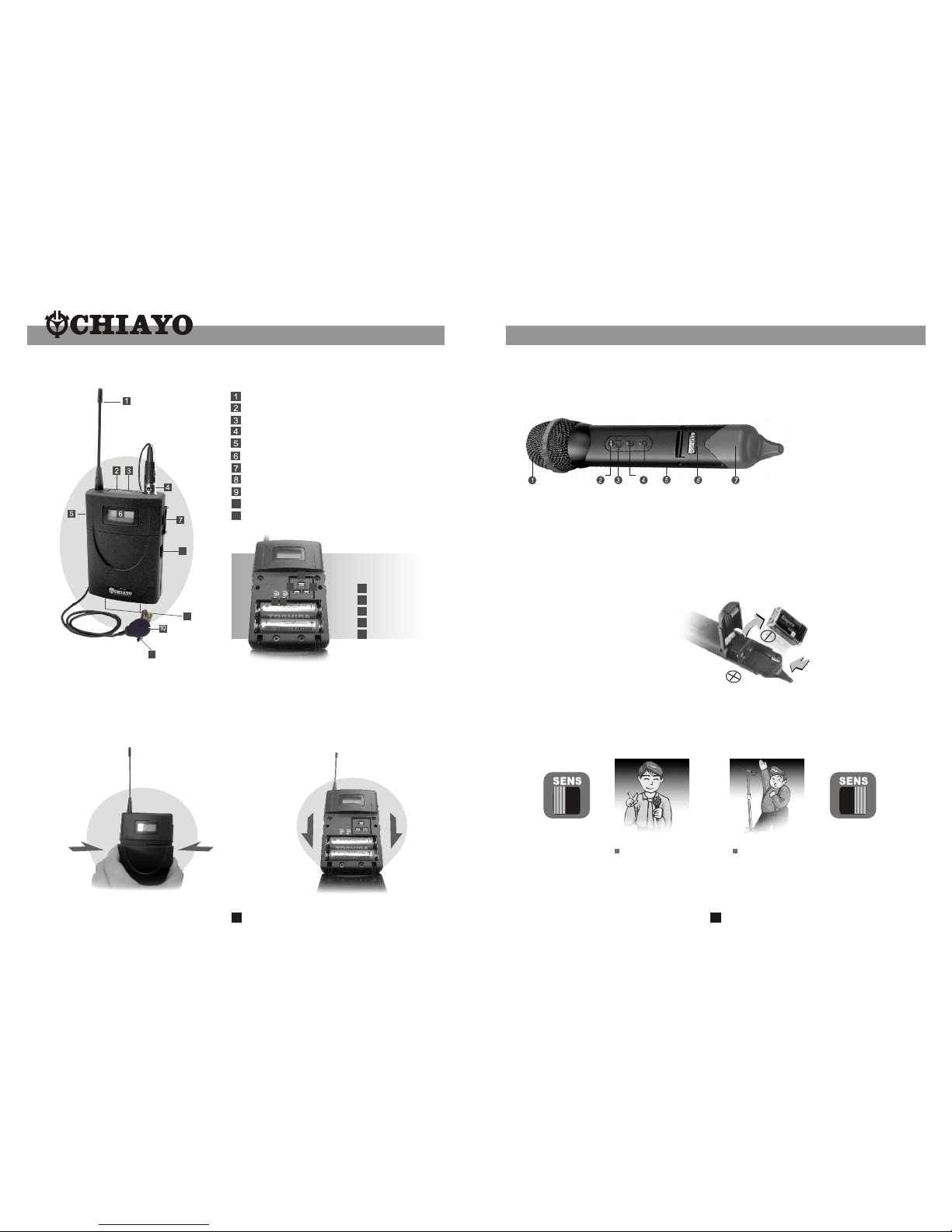
1. Before inserting the batteries, please make sure that they are inserted according to
the correct polarity.
2. The audio cable of VHF transmitters also serves as antenna. The length of the cable
is cut according to the specific frequency range. Do not alter the length or mix around
the cable of different transmitters. The use of wrong audio cable will affect the antenna
efficiency of the transmitter!
3. Use only brand new Alkaline batteries. Do not use " general purpose " batteries, When
batteries are weak, replace all the batteries at the same time. Do not mix and use new and
old batteries together.
4. Position the receiver such that it has the least possible obstructions between it and the
transmitter. Line of sight is best !
5.The transmitter and the receiver should be as close as possible but not less than 1m.
6. A receiver cannot receive signals from two or more transmitters simultaneously.
7. Turn the transmitter off when it is not in use. Remove the batteries if it is not to be
used for a period of time.
8. Antennas form an integral part of the receiver and must be installed when in Operation.
Simple DIY Trouble-shooting :
No sound when one speaks into the wireless microphone
Please verify the followings:
1.Main power switch of the system should be ON. When power on LED not lighting up,
it means that the battery is either weak or not charged. Please plug in the AC cable to
Charge the battery. The rechargeable battery has a life span of about 2 years. If the
batteries have reached their life expectancy, please change to a fresh pair.
2.The power switch of the corresponding receiver module should be put to ON. This is
indicated by the lighted power LED. When two wireless microphones are used, both
power switches of the receiver modules must be ON.
3.Wireless microphone should be switched to ON and verify that the battery is okay. (
please refer to wireless microphone operating manual ).
4.Please verify that the frequency on the wireless microphone and the corresponding
built-in wireless receiver module are exactly of the same frequency group and channel.
5.Master volume control of the system should be turned on.

4
10 W (RMS) / 2 Load
4" full range speaker
< 0.5%
Wired Mic / Line In
Built-in 12V / 2.7AH rechargeable Battery
about 4 hours
VHF / UHF receiver modules
VHF 160 - 260 MHz / UHF 600 - 900 MHz
Chiayo or other compatible brand
M-1002, Q-1002 / SM-916,SQ-916 / SM-5016,SQ-5016
Speaker out
247.5* 140* 152.5
2.7
Black
W
Max. Power Output
Speaker System
Distortion
Input
Power Supply
Charging Time
Receiver Module
Frequency Range
Wired microphone
Wireless microphone
Output
Dimension (H* W* D, mm)
Weight (Basic unit)(kg)
Color
Specification
Item Specification
15
Operating the dynamic wired microphone
There is a MIC IN jack with dedicated volume control for this portable sound unit. To
use a cable microphone ( dynamic only ), just plug the end with a phone jack plug into
MIC IN . Switch on the Power / volume control knob MIC ( H ) and rotate it clockwise,
amplified sound could be heard when voice is spoken into the cable microphone.
Battery Charging
Internally, the SMART 300 SMART Slave contain 1 piece of 12V / 2.7 maintenance-
free lead acid rechargeable battery, which has no memory effect. When the battery is
weak, the power indicator RED LED will light up if the main power is switched on.
To charge the battery, simply plug in the AC power supply, the charging process will
start automatically. While charging, the charging indicator will be in FLASH RED.
When battery is fully charged, the charging indicator will stay GREEN.
Operating the Digital USB Player
To use the USB 2.0 Player for playing MP3 files, simply plug your USB 2.0 into the port
after the player has been turned on. " PLAY / PAUSE", " MODE ", " Forward " and "
Rewind " buttons can be used to control during USB is in use. User is advised to have
the USB format in " FAT " or " FAT 32 ". The built-in USB player can not be able to read
the MP3 files stored in your USB if it is not formatted by either " FAT " or " FAT-32 ".
Secondly, USB in use can only be detached after the player has been shut off,
preventing the USB from being possibly damaged.
AH

14
5
Handheld Transmitter Q-1002(VHF)
Color cap
Battery status
LED indicator
Metal Grille
( Capsule module inside )
Power Switch
Battery compartment
cover
r sP e s
Battery Installation
Q-1002 uses 1 piece of 9V battery. To install new or replace the old battery, First unscrew the
battery cap from the battery compartment, then insert the new battery according to its correct
polarity as indicated. For longer operation hour, Alkaline battery is recommended!
slide to "ON" position
After putting the battery cover back to the housing , slide the switch to "ON" position as
shown below.
As soon as the power is on, the battery-status indicator will give flash, indicating a normal
operation. If there is no flash, it indicates either power supply is not available or battery is
installed wrongly.
After switching on, the Therefore signal indicator LED(s) of matching receiver will light up,
indicating the microphone signal transmission is in normal operation.
Switch off the power when the microphone is not in use, meanwhile, remove the battery out
of microphone if it is not to be used for an extended period.
Parts an d fun ct ion s
Making changes to various settings in SM-5016
1.Making changes to CHANNEL / FREQUENCY:
Use UP or DOWN button to go to the CHANNEL /FREQUENCY page.
The cursor will flash to allow changes to be made. Pressing UP or DOWN button
will increase or decrease the channel number. The corresponding frequency will
change accordingly. When a desired channel(frequency) is being selected, it will
be automatically saved and stored in the memory.
2.Making changes to Battery selection:
Use UP or DOWN button to go to the Battery selection page.
Press SET for about 2 seconds to activate the cursor. Press UP or DOWN button to
move the cursor to either NiMH ( rechargeable battery ) or AKLN ( Alkaline battery )
position.
When the desired option has been selected, press SET for about 2 seconds to save
and store the data in the memory.
Remark : When changing transmitter frequencies, care should be taken to
avoid causing interference to other channels / users.
Remark : NiMH battery must be selected when rechargeable battery is
being used. Never select AKLN ( Alkaline ) when transmitter is intended
for charging as Alkaline battery can not be charged ! Wrong selection of
battery will result in battery sensing electronics to display wrong and
mislead status information.
3.Input Level Gain Control Adjustment
Low impedance (Lo-Z) " MT" & high impedance (Hi-Z) " GT" gain controls are
situated inside the transmitter. Gain controls are adjustment ports that enable you to
use microphones of differing output levels and Guitar or instruments with Hi-Z
output. To adjust microphone (Lo-Z) input levels, turn the "MT" control and to adjust
the Guitar or instrument (Hi-Z) input, adjust the "GT" gain control to set the
transmitter's desired audio input level.

13 6
Belt-pack Transmitter SM-5016 (UHF)
8
10
11
Antenna
Battery weak / audio mute indicator
Audio mute switch
Mini-XLR connector
Power ON / OFF switch
LCD display
Mini USB port
Cover release button
Charging contacts
Lavalier microphone
Mic clip
12
13 14
1615
14
13
12 SET
UP
DOWN
GT
MT
15
16
9
11
Battery installation
SM-5016 uses 2 pieces of " AA " size batteries (Alkaline battery is recommended ).
To install or remove the batteries, press the release buttons at the edges of the
transmitter to open or close the cover as illustrated below.
L
N
L
N
Press
Hand-held microphones SQ-916(UHF)
SQ-916
Low Sensitivity High Sensitivity
Battery installation
SQ-916 uses a 9V battery for power. To change or replace the battery, please remove
the color cap first, then press the bottom of battery compartment to release the cover
as shown below.
Sensitivity switch
This microphone has a sensitiving switch, For colse mouth singing or normal speech, please
put the switch to L ( Low ) position. For tripod-mount speech, please put the switch to N
( Normal ) position.
1. Capsule with metal grille
2. Battery indicator
3. Sensitivity switch
4. Power on/off switch
5. Battery cover
7. Color cap

12
Installation of Lavalier /
Headset microphones or instrument inputs
Depending on customer requirements, Lavalier / Headset microphone or instrument
inputs could be connected to the transmitter via the audio input connector. User is free
to choose the various input sources but is advised to take note that connector used must
be compatible to each other. The pin configurations of mini XLR connector are as follow
.
ANTENNA
GT IN
LED INDICATOR
MT IN GND
PHANTOM POWER
POWER
SWITCH
POWER
OFF ON 1
2
34
mini XLR connector
Installation of cable restraint
To prevent contact noise caused by constant tension
applied to the connector, a cable restraint is designed such
that tension is totally reduced when it is properly used.
When the audio cable goes through the cable restraint, it
could prevent sweat from going directly into the electronic
board via the connector.
This is another advantage of the cable restraint.
7
Operating instructions
1.Before operation, please check and make sure that transmitter & receiver are of
matching frequency or frequency group.
2.To switch on the microphone, put the switch to "ON" position. The green LED
indicator will light on to indicate that battery is fresh. When RED LED light on, it
indicates that battery is weak, thus a replacement is necessary.
3.For best result, alkaline battery is recommended. Please remove the battery if the
transmitter is not to be used for a longer period.
4.When necessary, mic capsule could be replaced by pulling out and plugging in the
new one, either dynamic or condenser for SQ-916.
Changing capsule
This microphone has a module design. To change or replace a capsule, Open the grill
to pull out and plug in the capsule as shown in the following figure.

11 8
MT
Channel
GT
Selector
Beltpack Transmitter SM-916 (UHF)
Battery in sta lla tio n
SM-916 uses a 9V batte ry. To insert th e batte ry,
first open the batte ry compartm ent cover by
pressing the cover downward till th e door fl ips
open by its elf (see below picture). When insta lling
the batte ry, please beware of correct polarity . To
put back th e cover of the batte ry compartm ent,
one has to press the cover in upward dire ction
until it is locked.
Battery status
Indicator
Power switch
Audio input
Connector
Battery
Compartment
Cable
restraint
Mike clip
Capsuale
Antenna
Channel selection and gain adjust
Channel selector and gain adjust are hidden in the designated cover of the front as
illustrated.
To make channel selection and gain adjust, please press the designated cover and
flip it open as illustrated.
Channel selection can be made by
rotating the selector with a small
screw driver.
Gain adjust for Lavalier and Headset
microphones can be done by adjusting
the MT switch, whereas GT switch is
for the gain adjust of electric Guitar
and other high- impedance line level
inputs.
Fig.1
Battery installation
SQ-5016 microphone requires 2 pieces of " AA " size batteries
to operate. Please insert the batteries according to the correct
polarity as indicated.
Handheld Transmitter SQ-5016(UHF)
. Microphone capsule module
. Battery status LED
. ON/OFF switch
. LCD
. Battery compartment
. Rotating protective cap for controls
(also serves as color identification cap)
1
2
3
4
5
6
Caution
Many batteries are known to have leakage problem of conductive and corrosive liquid.
Please observe the rule to remove the batteries if they are not to be used for a longer
period.
Due to various unstandardized sizes ( diameters ) of " AA " batteries, this battery
compartment is designed to accommodate the most commom Alkaline batteries only.
Changing of capsule
First unscrew the metal grill from the housing and take out the capsule to be replaced. Then
insert a new capsule. Either dynamic or condenser type can be chosen from location to
location.
. Lock / Unlock
. Set
. Up
. Down
. Charging port
. Name plate
7
8
9
10
11
12
Parts and functions

10
9
3. Making changes to Sensitivity Level:
Use UP or DOWN button to go to the SENS SET page.
Press UP or DOWN button to increase or decrease the Sensitivity Level of the transmitter.
The MAX level is 4 and the MIN level is 1.
When a desired sensitivity level has been selected for your application, it will be
automatically saved and stored in the Memory.
Remark : When selecting Sensitivity level, please bear in mind that Level 1 is for
close proximity singing purposes whereas Level 4 is for use of transmitter on
tripod mount for speech purposes. When Level 4 setting is used for close
proximity singing, high SPL input will result in undesirable distortion in the
output.
After performing setting changes, you could turn the protective cover 180° in either
direction to block the buttons from being accidentally adjusted.
1.Making changes to Channel:
Use UP or DOWN button to go to the CHANNEL/ FREQUENCY page. The cursor will flash
to allow changes to be made. Pressing UP or DOWN button will increase or decrease the
channel number. The corresponding frequency will change accordingly. When a desired
channel is selected, it will be automatically saved and stored in the memory.
2. Making changes to Battery selection:
Use UP or DOWN button to go to the Battery selection page.
Press UP or DOWN button to move the cursor to either NiMH ( rechargeable battery ) or
AKLN ( Alkaline battery ) position.
When the desired battery has been selected, it will be automatically saved and stored in the
memory.
Making changes to various settings in SQ-5016
Remark : NiMH battery must be selected when rechargeable battery is being
used. Never select AKLN ( Alkaline ) when transmitter is intended for charging as
Alkaline battery can not be charged ! Wrong selection of battery will result in
battery sensing electronics to display wrong and misleading status information.
Parts an d fun ct ion s
Belt Clip
This uniquely designed belt clip allows 360
degree rotation. Select the best position
to achieve optimum wearing comfort.
Battery Installation
M-1002 uses 1 piece of 9V battery. To install
new or replace the old battery, first open the
battery compartment cover, then insert the
new battery according to its correct polarity as
indicated. For longer operation hour, Alkaline
battery is recommended!
360 rotate able
belt clip.
Beltpack Transmitter M-1002 (VHF)
MIC clip
MIC capsule
Battery
compartment
Battery compartment
cover
Power Switch Battery status
indicator.
MIC cable
MIC IN socket
MT
Input level Gain control adjustment
Low-impedance "MT" gain control is situated inside the beltpack transmitter. Gain
control port is an adjustable design that enables user to use microphones of different
output levels. To adjust the audio input levels, simply use a small screw driver to
switch the "MT" control till a desired level is chosen.
Other manuals for Smart 300
2
Other Chiayo Speakers manuals

Chiayo
Chiayo Focus 500 series User manual

Chiayo
Chiayo VICTORY 2000 User manual

Chiayo
Chiayo Challenger 1000 User manual

Chiayo
Chiayo Coach 400 Series User manual

Chiayo
Chiayo Focus 505 series User manual

Chiayo
Chiayo Challenger 1000 User manual

Chiayo
Chiayo Challenger 1000 User manual

Chiayo
Chiayo Smart 300 User manual

Chiayo
Chiayo Challenger 1000 User manual

Chiayo
Chiayo STAGE PRO User manual