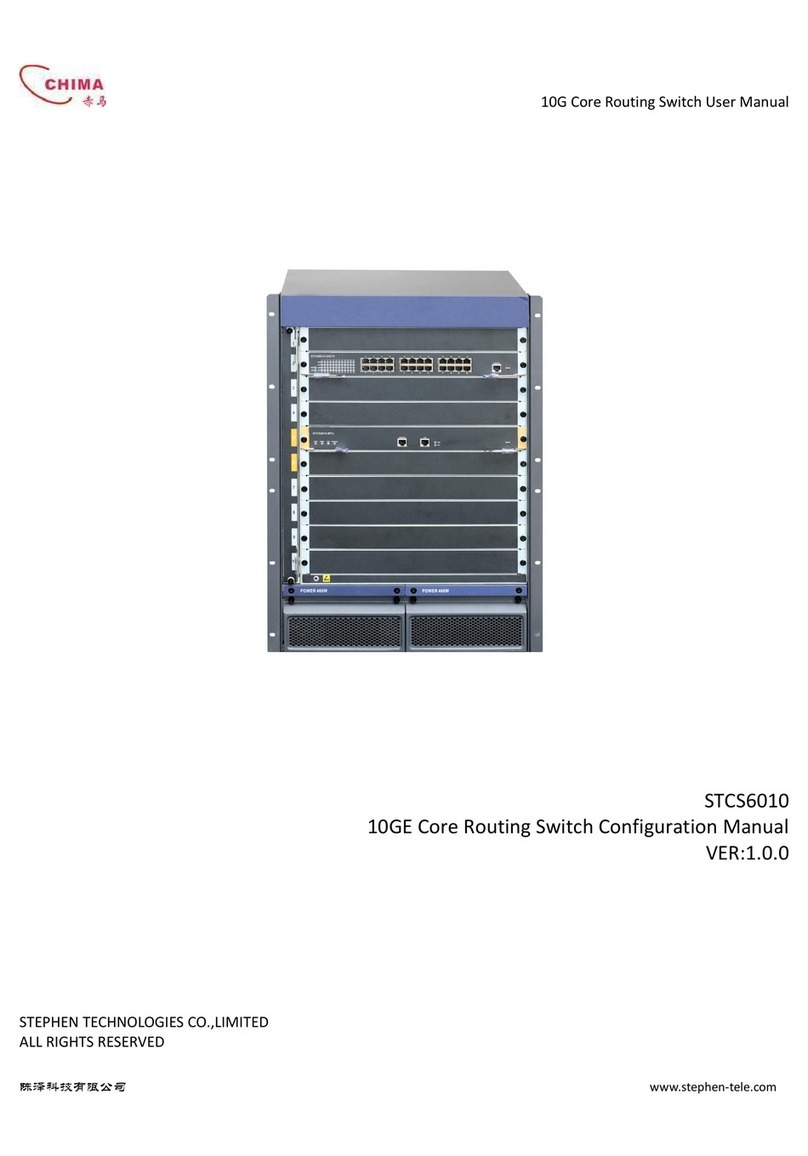
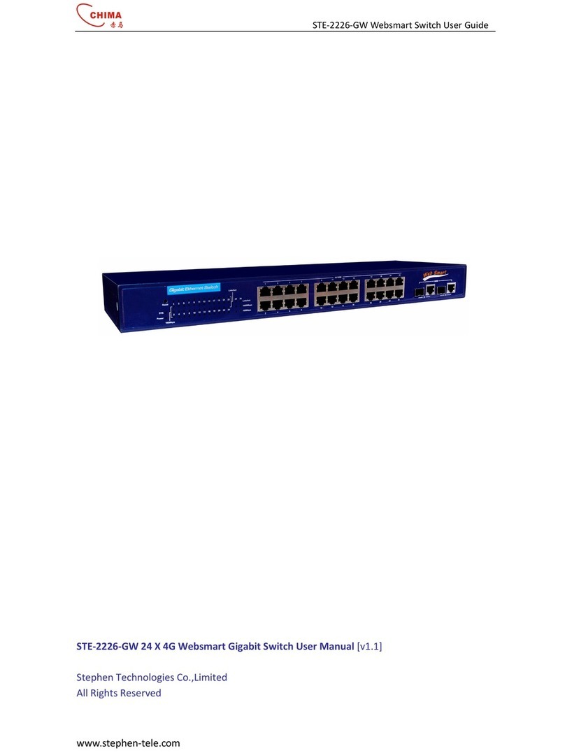
Chima STES2026+ User manual

STES2026+ Layer 2 Man
aged Switch User Manual
陈泽科技有限公司
www.stephen-tele.com
1
STES2026+ 2 Port 10/100Base-Tx + 2 Port Giga SFP + 2 Port Giga Ethernet
Layer 2 managed Ethernet switch User Manual [V1.3]
STEPHEN TECHNOLOGIES CO.,LIMITED
ALL RIGHTS RESERVED

STES2026+ Layer 2 Man
aged Switch User Manual
陈泽科技有限公司
www.stephen-tele.com
2
Table of Contents
Packing List
Chapter 1 About this User’s Guide
1.1 Usage
1.2 Assumpsit
1.3 Overview of this User’s Guide
Chapter 2 Introduction
2.1 Overview of the Product
2.2 Features and Specification
2.2.1 Features
2.2.2 Specification
Chapter 3 Installation
3.1 Installation
3.1.1 Desktop or Shelf Installation
3.1.2 Rack Installation
3.1.3 Power on
3.2 Connecting the Switch
3.2.1 Front Panel
3.2.2 Rear Panel
3.3 Remarks
Chapter Introduction to switch configuration
.1 System configuration
.1.1 System information
.1.2 Switch infromation
.1.3 System passport setting
.1. File transfer
.1.5 Save and Reset
.1.6 WEB and Telnet management control
.2 Port management
.2.1 Port Parameters
.2.2 Port Mirroring
.2.3 Port description
.2. Port statistic and status
.2.5 Port bandwidth
.2.6 Port storm control
.3 Network Management
.3.1 IGMP snooping
.3.2 Static IGMP setting
.3.3 IP address setting
.3. Mac address aging time and dynamic address table(FDB Table)
.3.5 MAC address binding
.3.6 Switch ARP table

STES2026+ Layer 2 Man
aged Switch User Manual
陈泽科技有限公司
www.stephen-tele.com
3
. VLAN management
. .1 IEEE802.1Q Tag VLAN
. .2 Port-based VLAN
. .3 Protected Vlan
.5 Trunk configuration
.6 QoS management
.6.1QoS Global configuration
.6.2 Port-based priority
.6.3 TOS priority
.6. 802.1P priority
.6.5 802.1p priority reflected table(802.1p priority remapped table)
.7 STP
.7.1 STP realzation
.7.2 STP Port Status
.8 SNMP and RMON management
.8.1 SNMP protocol
.8.2 RMON protocol
.9 Port Access Entity(802.1x)
Chapter 5 WEB management
5.1 Summrize
5.2 WEB management link
5.2.1 Ready work
5.2.2 Link
5.3 WEB management interface and operation method
5.3.1 System configuration
5.3.2 Port management
5.3.3 Network management
5.3. VLAN management
5.3.5 Trunk configuation
5.3.6 QOS configuration
5.3.7 STP configuration
5.3.8 SNMP setting
5.3.9 802.1x Configuration
Chapter 6 Out-of-band management
6.1 Summrization
6.2 Out-of-Band conection
6.3 Out-of-Band management interface and operation method
6. CLI command grammar and user help
6. .1 Grammar introduction
6. .2 Introduction to previous menu configuration
6. .3 Introduction to aaa command configuration
6. . Example of aaa configuration
6. .5 IGMP snooping

STES2026+ Layer 2 Man
aged Switch User Manual
陈泽科技有限公司
www.stephen-tele.com
4
6. .6 Introduction to port mirroring command configuration
6. .7 Example to port mirroring command configuration
6. .8 Introduction to network configuration command
6. .9 Introduction to port configuration command
6. .10 Introduction to QoS configuration command
6. .11 Example of QoS configuration
6. .12 RMON configuration command
6. .13 Introduction to SNMP configuation command
6. .1 Introduction to STP configuration command
6. .15 System configuration command
6. .16 Trunk configuration command
6. .17 Example of Trunk configuration
6. .18 Introduction to VLAN configuration command
6. .19 Example of VLAN configuration
Chapter 7 Telnet Management
7.1 Summerization
7.2 Telnet
7.3 Connection
Chapter 8 SNMP Management
Checklist
The following contents should be in your box:
One Switch
One AC power cable
One Serial cable
One user’s Guide
L-type Brackets
Note: If any of the listed contents are damaged or missig,please contact the retailer from whom you purchased the
Switch for assistance.

STES2026+ Layer 2 Man
aged Switch User Manual
陈泽科技有限公司
www.stephen-tele.com
5
Chapter 1 About this User’s Guide
Thank you for purchasing STES2026+ Gigabit management Ethernet switch.. The series provide powful
management functions. With the features of high-performance,easy -to use, the STES2026+ is the a good choice
for you.
1.1 Usage
This User’s Guide tells you how to use STES2026+ Gigabit management Ethernet switch..
1.2 Assumpsit
The Switch indicated in the User’s Guide is the STES2026+ Gigabit management Ethernet switch.
1.3 Overview of this User’s Guide
Chapter 1 About the User’s Guide
Chapter 2 Introduction Describes the switch and its features
Chapter 3 Installation Help you to get started with the basic installation of the switch
Chapter General conception of Switch
Chapter 5 WEB Management
Chapter 6 TELNET/Out-of-Band Management Describes how to management
Chapter 7 TELNET Management
Chapter 8 SNMP Management

STES2026+ Layer 2 Man
aged Switch User Manual
陈泽科技有限公司
www.stephen-tele.com
6
Chapter 2 Introduction
2.1 Overview of the product
STES2026+ Gigabit management Ethernet switch fully complies with IEEE802.3 Ethernet standard, its intelligent management
make it suitable for small, middle and large networks solution.
STES2026+ Gigabit management Ethernet switch provides powful management functions including the system, port, network,
VLAN, Truck, priority and security management etc.
You can manage the switch through WEB browser and you can also check the system configuration, modify IP network
parameter, and modify login password through the RS232 serial port.
STES2026+ Gigabit management Ethernet switch with 2 100Mbp ethernet copper port and 2 Gigabit copper port with 2 Giga
SFP COMBO slot, can extend next generation network connection.
2.2 Features and Specification
2.2.1 Features
● Fully comply with IEEE 802.3,IEEE 802.3u,IEEE 802.3ab,IEEE 802.3z, IEEE 802.1Q,
● IEEE 802.1D, IEEE 802.1x standard
● Support IEEE 802.3x flow control for full-duplex mode and collision-based back-pressure for half-duplex mode
● STES2026+ support 2 100M Auto-Negotiation RJ 5 ports,
● 2 Giga Auto-Negotiation RJ 5 ports
● Provide 2 Giga SFP optical extend slot and share with 2 Giga RJ- 5 port
● Support RJ- 5 port Auto MDI/MDIX
● Provide one DTE equipment configuration serial port.
● Support Ip address setting and dynamic learning(DHCP)
● Support 26 Port-based VLAN, 256 IEEE 802.1Q VLAN
● Support Protected VLAN
● Support MAC address binding
● Support IGMP Snooping
● Support STP protocol and against a loop occurring between switches
● Support 802.1x protocol and authenticating users to gain access to Local Area Network by using a Client and Server
based access control model
● Support port trunk function, port mirroring
● Support port priority, TOS priority, IEEE 802.1 p priority
● Support IEEE 802.1p priority remap
● Support broadcast/multicast/dlf storm control, it can reduce broadcast/multicast/dlf storm
● Support bandwidth control,The miximum granularity is 6 Kb
● Support WEB management interface and console/telnet tftp upgrade, local Xmodem upgrade
● Provide SNMP, WEB and Telnet/Console management
● Support SNMP V1, V2, and RMON
● Dynamic LED indicator, provide simple work state indication and malfunction obviation
● Internal excellent power supply, high stability and reliability
● 1U steel case, radiate heat quickly
● Support standard 19 inch rack mount.

STES2026+ Layer 2 Man
aged Switch User Manual
陈泽科技有限公司
www.stephen-tele.com
7
2.2.2 Specification
Model STES2026+
Standards and Protocols IEEE802.3
、
IEEE 802.3u
、
IEEE 802.3x
、
IEEE 802.3ab
、
IEEE 802.1Q
、
IEEE 802.1x
、
IEEE802.1D
Port No. 1000M 2
100M 2
SFP slot 2
Network Medium 10Base-T
:
UTP category 3 or above
;
100Base-TX
:
UTP category 5
;
1000Base-T
:
UTPcategory 5 or 6 or SFP port support single mode or multi-mode optical modules
MACAddress table 8K
Backboard bandwidth 8.8G
Filter and Transfer Rates 10Mbps: 1 880pps; 100Mbps: 1 8800pps; 1000Mbps: 1 88000pps
LED
Indicator
Link/Act Light up/Blinks
100M Light up
Other Power
Dimension(L×W×H)
(mm) 0×205×
Environment Operating Temperature
:
0
℃
~ 0
℃
;
Operating Humidity 10
%
~90
%
non-condensing;
Storage Temperature
:
- 0
℃
~70
℃
;
Storage Humidity 5
%
~90
%
non-condensing
Input Input
:
180-2 0VAC
,
50-60Hz
;
Fig 2-1 STES2026+ specification table
Chapter 3 Installation Guide
3.1 Installation
Follow these steps to install the switch:
The surface must support at least 5kg
The power source must be within 1.5m
Make sure the power cable has connected to the power socket in the back panel of the switch and the power supply
slot.
Make sure the switch is in a breezy environment and good for cooling the switch. Don’t put heavy things on the switch.
3.1.1 Hardware Installation on the desktop
1.Put the switch upside-down on a steady and big enough desk
2.Tear off the protective paste on the pads, and paste them in the circular slots in the underside of the switch.
3.Turn the switch over, and put it on the desktop.

STES2026+ Layer 2 Man
aged Switch User Manual
陈泽科技有限公司
www.stephen-tele.com
8
3.1.2 Hardware Installation on the Rack
The dimension of the switch is compliant with the EIA(Electronic Industries Association) standard 19 in rack.
1. Fix up the 2 L-type Brackets on the two lateral side of the switch. (The accessories contain the bolts)
2. Put the switch on the shelf.
3. Fix up the switch (bolts is provided by the user.)
Fig 3-1 L-type Brackets installation
3
.
..
.
1
.
..
.
3 Power Supply
The power supply input of the switch is AC 180-260V(50-60Hz), the internal power system of the switch can auto-regulate the
working power according to the actual input power. When the switch is power on, the Power indicator light on the front
panel of the switch shines.
Notice
:
When the power supply is off, to make sure the switch won’t be damaged by sudden great power, please pull off the power
cable from the power supply socket. And plug in when the power supply is well balanced.
3
.
..
.
2 Appearance of the Switch
Describe the front panel and back panel of the switch in details.
3
.
..
.
2
.
..
.
1
1) STES2026+ front panel is made up of 2 SFP slots, 2 1000M ports,2 10
/
100Mbps ports, 1 Console port
(
RS232
serial port
)
and LED indicators, as the following:
Fig 3-2 STES2026+ Front Panel
Serial Port
Serial Port (Console port or RS232 port) is on the right of the front panel. It’s the port for connecting to the computer when
use the Out-of-band Management. You can configure the system information, network parameter and security management
through CLI.
2 SFP slot
2 SFP slot is on the left of the serial port, support 1000M optical modules.
2 10Base-T/100Base-TX/1000Base-T RJ- 5 port
2 1000M ports are on the left on the SFP slot, they support 10Mbps, 100Mbps or 1000Mbps bandwidth joint equipment,
and auto-negotiation. Each port has 3 LED indicators, Link/Act indicator, Speed indicator, and SFP indicator.
2 10Base-T/100Base-TX RJ- 5 port
On the left of the 1000M port are 2 10
/
100M ports. They support 10Mbps or 100Mbps bandwidth joint equipment, and

STES2026+ Layer 2 Man
aged Switch User Manual
陈泽科技有限公司
www.stephen-tele.com
9
they all support auto-negotiation. Each port has 2 LED indicators, Link/Act indicator, and Speed indicator.
Indicators
Indicators are on the left of the panel.
System indicator
1. Power indicator
It’s on the left. When the switch power supply is on, the indicator shines red light. If the indicator doesn’t shine, check if the
power supply is connected.
100M port indicator
1. Link/Act indicator
When a port is connected to 100Mbps equipment, the relative LED shines green light, and when there is data transferring,
the LED blinks.
2. Speed indicator
When a port is connected to 100Mbps equipment, the relative LED shines green light.
1000M port indicator
1. Link/Act
When a port is connected to 1000Mbps equipment, the relative LED shines green light, and when there is data transferring,
the LED blinks.
2. Speed indicator
When a normal port connected to a 100Mbps equipment, the relative LED shines green light. When a normal port connected
to a 1000Mbps equipment, the relative LED blinks green light.
3. SFP indicator
When the 1000M SFP is used, the indicator shines green light.
Notice: SFP indicator is on the right of the indicators group. In the same line with Link/Act indicators.
Notice: The 1000M port and the 1000M SFP slot are combo. When the 1000M port is used, the relative 1000M SFP slot can
not work, vice versa, when the 1000M SFP slot is used, the relative 1000M port can not work.
2) The STES2026+ switch front panel is made up of 2 10
/
100Mbps ports, 2 1000M ports, 1 Console port
(
RS232 serial
port
)
and LED indicators, as the following:
3
.
..
.
2
.
..
.
2 Back Panel
There is a power supply socket in the back panel of the switch. The power input is :180-260V
~
50Hz-60Hz.
Fig 3-3 STES2026+ Back Panel

STES2026+ Layer 2 Man
aged Switch User Manual
陈泽科技有限公司
www.stephen-tele.com
10
Power supply socket
This is a two-circuit three-phase Power supply socket. Plug the cathode pin of the power cable in this socket, and plug the
anode pin in the AC power supply.
3.
..
.3 Notice
1) When moving the switch, be careful and keep steady. If the switch falls down, it may suffer serious damage.
2) The switch requires normal power supply for working at normal, please check if the power supply is compliant with the
power requirement of the switch.
3) To reduce electric shock dangerous, don’t open the case of the switch when it’s working, and don’t try to open it yourself
even when power off.
) If the switch is connected to the workstation, server, HUB or other switch by UTP cable, the UTP cable should be not
longer than 100m.
For 10Base-T Ethernet, the cable used should be UTP category 3 or above.
For 100Bas-TX Ethernet, the cable used should be UTP category 5 or above.
For 1000Bas-TX Ethernet, the cable used should be UTP category 5 or category 6 above.
You can plug in or pull out the cable when the switch is working. It won’t disturb the switch.
If you want to clean the switch, please pull out the power pin first, and use wet cloth to clean, don’t use liquid.
Don’t put the switch near water or wet environment, to avoid that the water or moisture gets in the switch.
Please avoid the dusty environment and environment with strong Electromagnetic Interference.
Chapter Summrization of switch configuration
This chapter introduce the configuration of STES2026+. In these following configuration ,some is for WEB or CLI. But most
are for both WEB and CLI.
.1 System configuration
Switch system configuration is used to set up the system description,system position , the idle time of CLI and website,modify
administer passport,upgrade system software,save and upgrade file of system configuration ,restore the switch to factory
setting and restart switch.. Following is the details of some configuration.
.1.1 System information
This configuration is composed of system running time , system name , idle time of web page,and CLI idle time.Following is
these configuration explaination.
System running time :the time is form the system powering on to the end .
System ID: Manufacturer’s SNMP node information.
Web page idle time : If user have no operation to switch through web in this time, switch will return to the login web page .
CLI idle time: If user have no operation to switch through CLI in this time, switch will return to the login menu.
System name and position : User can modify configuration to distingush position of this switch.
.1.2 switch information
This configuration is for openning and closing each protocols.It aslo for STP,IGMP Snooping, DHCP, 802.1x.
STP: STP protocol is compliant with IEEE 802.1D standard,and against a loop occurring between switches.
IGMP Snooping:In normal condition , switch broadcast the multicast packet to all ports, To avoid consume the switch’s source.
Opening IGMP Snooping protocol to monitor all IGMP packet, and establish mutlicast entry in the switch, multicast packet
will only forward to the port defined in the multicast entry. More details can refer to following explaination of Igmp Snooping.

STES2026+ Layer 2 Man
aged Switch User Manual
陈泽科技有限公司
www.stephen-tele.com
11
DHCP: open DHCP function, switch get IP address through long-distance DHCP server instead of switch static IP address. More
details for DHCP protocol, please refer to IP address parameter. (Note: open or close DHCP protocol, please save configuration
and reset switch. If DHCP server is not exist or get no IP address for some other reason , switch use static IP address.
802.1x: The IEEE 802.1x standard is a security measure for authorizing and authenticating users to gain access to various
wired or wireless devices on a specified Local Area Network by using a Client and Server based access control model.. Open
802.1x protocol, combine with switch port 802.1x configuration, radius server configuration, it can realize identifying switch
user function . More details ,please refer to 802.1x protocol.
.1.3 Setup system password
This configuration can modify switch administer password, administer name is “admin”,WEB and CLI (Out-of-Band ) use the
same user name and password.Default password is admin. User can modify this password. Password length is 1-16 character
which must be english character or ” (),and password need identify upper-case letter and lower-case letter.
.1. File transfer
This configuration can upgrade the image, system configuration and make a backup online.
This function is through TFTP protocol. TFTP (Trivial File Transfer Protocol) is a simple protocol based on UDP protocol for file
transfer. It deal with the file through two station.
Network need a TFTP file server We fill TFTP file server IP address in switch. If upgrade system file and cofiguration file, we
need provide correct name of the file. When upgrade system and configuration file, we must put upgraded file in the root
directory TFTP server appointed. When we make a backup file ,configuration file from switch will saved in root directory TFTP
server appointed.
.1.5 Save and Replacement
This configuration provide switch restart and restore the switch to factory configuration. after restore the switch to factory
configuration, present configuration will lost .(Note: after restore the switch to factory configuration,switch restart
automatically)
.1.6 WEB and TELNET mangement function control
This configuration used to open or close WEB and TELNET.User manage switch through long-distance login in web and
telnet.If WEB and TELNET is closed, we manage switch through One serial cable
.2 Port management
STES2026+ Switch offers 2 100M port ,2 10Base-T/100Base-TX/ 1000Base-T RJ- 5 port and 2 SFP extension slot. Switch can
set port parameter, port mirroring,port description, get port statics information and status,control port bandwidth and
broadcast/dlf/multicast storm.
.2.1 Port parameter
Open and close port ,and flow control ,opertaion mode setting ,setting port default VID,and method of dealing with TAG
frame.Last two item can be set based on IEEE802.1Q Tag VLAN mode. Following is the description of each configuration item
function :
Port mode: Setting port mode to Enable, this port can transfer and exchange data flow . Setting port mode to Disable,this
port connect normally but can not transmit data flow normally.
STP mode:open STP function ,setting port STP mode to Enable, port attend detection of STP loopback.setting STP mode to

STES2026+ Layer 2 Man
aged Switch User Manual
陈泽科技有限公司
www.stephen-tele.com
12
Disable, port cannot attend . More details, please refer to this chapter introduction to STP protocol.
Flow control
Flow control means switch control speed of receiver and sender . When receiver received ability is lower than sender sent
ability , flow control lose no data.Flow control have two type: one is half-duplex, another is full-duplex. half-duplex flow
control meet Backpressure standard.full-Duplex flow control based on PAUSE frame flow control ,meet IEEE802.3x standard.
In half-duplex mode,receiver source is not enough ,they will start flow control,send a group carrier wave pluse train (artificial
collision signal ), sender detect network carrier wave which is different with their own sent signal, they will pause for a short
time ,then send data. Receiver can deal with data in this time and control flow. This is Backpressure standard.
In full-duplex mode,receiver source is not enough, receiver send a pause frame to sender that they will stop sending data for
a short time . This is IEEE802.3x standard .
Open port flow control,speed of data flow which flow in or from this port is over this port largest speed.half-duplex choose
backpressure, sender speed down by PAUSE frame,Close port flow control, switch discard package which linear velocity is
over this port.
Negotiation method: 100Mbps Switch , 100Mbps port have 5 work mode , 1000Mbps has 6 work mode as following
Auto: Auto-negotiation
10Mbps
/
HD:10M Full Duplex mode
10Mbps
/
FD: 10M Full Duplex mode
100Mbps
/
HD: 100M half-duplex mode
100Mbps
/
FD: 100M Full Duplex mode
1000Mbps
/
FD: 1000M Full Duplex mode
Front number is transfer speed,back number is Duplex mode.Half Duplex mode is both transfer side sending and receiving
file.But at the same time ,only one equipment use network transfer medium . Full Duplex is both transfer side sending or
receiving at the same time. Normal 10Base-T
/
100Base-TX port have the front 5 work mode.For STES2026+, STES2026+
offers 1000Mbps shared port. When it works in copper port mode ,the 6 mode above all can work . When it work in optical
mode, 1000Mbps port can only be used in 1000Mbps/FD work mode.
Untag data frame control : when switch work in 802.1Q vlan mode,when the switch port received the frame without 802.1Q
VLAN TAG. At this time, switch can choose transmit data frame normally or throw it away through Untag data frame control .
Port default VLAN ID: PVID is short for port default VLAN ID.If you open 802.1Q VLAN mode and data frame received from
port have no 802.1Q VLAN TAG,switch will put PVID in data frame,and search VLAN group , transmit it and control it
according to PVID data. More details ,please refer to 802.1Q VLAN in this chapter. (Note: Switch cannot modify PVID data
when work in PORT VLAN or PROTECTED VLAN mode)
.2.2 Port mirroring
Port mirroring is one or more port ingress ,egress, ingress and egress monitored by one port.Based on above monitor
configuration ,you can choose ingress egress monitored type: all ,destination MAC address, source MAC address (SA).If you
choose ingress and destination MAC address (DA) monitored ,they only monitor passed package setted by MAC address.
Monitor interval ranges from 0 to 1023. When monitor interval set at 1023, package passed monitor port and meet monitor
require will be copy and send to monitor port at an interval of 1023.When you set at 0,there is no interval and it’s monitored
100%

STES2026+ Layer 2 Man
aged Switch User Manual
陈泽科技有限公司
www.stephen-tele.com
13
.2.3 port description
Port description is one port described one character, so network administer distinguish function of each port. Charater
number is at most 8 Chinese character or 16 English character or 16 number.
.2. port statistics and port status
Port statistics deal with each port data flow,broadcast frame, multicast frame,wrong frame count.Following is the concept for
statistic member:
ifInOctets: The number of received bytes.
ifOutOctets: The number of transmitted bytes
ifInUcastPkts: the number of received unicast packets.
ifOutUcastPkts: the number of transmitted unicast packets.
ifInNUcastPkts: the number of received multicast and broadcast packets.
ifOutNUcastPkts: the number of transmitted multicast and broadcast packets
ifInDiscards: the number of received discarded frames
ifOutDiscards: the number of transmitted discarded frames
ifInErrors: the number of received frames with frame align error
ifOutErrors: the number of transmited frames with frame align error
ifInUnknownProtos: the number of received frames with unknown protocol
Pkts6 Octets: the number of received and transmited frames under the size of 6 bytes (total length) .
Pkts65to127Octets: the number of received and transmited frames within size 65 to 127 bytes (total length) .
Pkts128to255Octets: the number of received and transmited frames within size 128 to 255 bytes (total length) .
Pkts256to511Octets: the number of received and transmited frames within size 256 to 511 bytes (total length) .
Pkts512to1023Octets: the number of received and transmited frames within size 512 to 1023 bytes (total length)
Pkts102 to1518Octets: the number of received and transmited frames within size 102 to 1518 bytes (total length)
Notice :byte number of packet is limited from 6 to 1518.If not in this limit ,the data frame is error.
You can view port status if port linked with switch, port operation speed ,port duplex mode, port flow control.More
details,please refer to port parameter.
(Note: The flow control status viewed from port status is not stand for the flow control status.)
It only stand for switch flow control configuration.Realizing flow control need port and port negotiation ,.only open switch
flow control ,it can come into effect.)
.2.5 port bandwidth
The bandwidth control settings are used to place a ceiling on transmitting and receiving data rates .
100Mbps:
6 Kbps\128Kbps\256Kbps\512Kbps\1Mbps\2Mbps\ Mbps\8Mbps\16Mbps\2 Mbps\32Mbps\6 Mbps\100Mbps.
1000Mbps:
6 Kbps\512Kbps\2Mbps\ Mbps\8Mbps\16Mbps\32Mbps\6 Mbps\80Mbps\120Mbps\200Mbps\ 00Mbps\6 0Mbps\800M
bps.
Open 802.1Q VLAN,data package pssed port have no VLAN TAG,so switch will add character VLAN TAG in this package ,as
the following figure.
DA
SA
Type
Data
CRC

STES2026+ Layer 2 Man
aged Switch User Manual
陈泽科技有限公司
www.stephen-tele.com
14
In this way, when switch calculate the bandwidth, will add new byte in it, so, when switch calculate the inflow port
bandwith, and the 802.1Q function is on, now if the inflow data without VLAN TAG, this time inflow data rate bandwidth
control rate is small than setting rate. For example, if bangwidth control the without VLAN TAG data bandwidth is 6 Kbytes,
in fact the bandwidth control will be about 62Kbytes.
.2.6 port broadcast storm
Swtich port received three type broadcast: normal broadcast ,mutlicast,unicast package with Destination Lookup Fail(DLF
package /UL package),every port can chose which storm they want to control and package transmit ratio.
Following is concept description of three data package broadcast storm control,following fig is basical format of ethernet.
Broadcast package
broadcast package is ethernet package with destination MAC address FF FF FF FF FF FF.
multicast package
multicast package is the first character of destination MAC with 1.
DLF package
DLF package or UL package is the ethernet frame that MAC address can not lookup form address table(FDB) of the switch, and will
broadcast in the VLAN area. About the detail description of Mac address should be consult the charter “FDB Table(arl table)” of this
user guide.
When storm break out ,switch control broadcast transmit ratio which has four type: 3%,5%,10%,20%. Transmit ratio is relative to
linear speed,that is to say, relatived transmited ratio is 3%*100M
、
5%*100M,10%*100M,20%*100M, above this limit will be
discard by broadcast package.
Note:
Basical conception of broadcast storm please refer to .1.2
.3 Network configuration
DA
SA
Tag
Type
Data
CRC
0X8100
Priority
CFI
VLAN ID
DA
SA
Type
Data
CRC

STES2026+ Layer 2 Man
aged Switch User Manual
陈泽科技有限公司
www.stephen-tele.com
15
Network configuration allow us setting switch IGMP SNOOPING ,static state mutlicast,IP address parameter,aging time ,MAC
address binding configuration, At the same time , we can view switch present binding multicast address and port present
MAC binding address,switch present FDB table(ARL Table),ARP table in switch.
.3.1 IGMP Snooping
Most switch deal with IP multicast as broadcast data.They transmit data to all switch port,not consider if this port need. IGMP
is IP group protocol that router and its mianboard exchanged information. STES2026+ support IGMP Snooping function. This
function can detect IGMP massage and get IP group information . Switch will hold up IGMP router and the IGMP frame from
IGMP Host, parse and transmit it,setting the switch module rule of IGMP frame, made the IGMP frame from Router to the
port needed.
Switch is learning the IGMP frame between IGMP router and IGMP host, establish the IGMP table, control the package of this
IGMP group just transmit between the IGMP member ports, avoid the IGMP frame to broadcast in the switch, if the
application is VOD, and the data steam is very great, this function can reduce the loading of the switch and the data flow not
necessary.
Traditional switch IGMP monitoring network as following fig:
Multicast group attended:
Multicast server or multicast router send multicast IGMP query message at normal condition. Some is for general massage
searching, other is for particular message searching . Received this multicast searching message, switch sent this message
transmit to the same VLAN port, Mainboard of this port received searching message and have an interest in it ,it will reply a
IGMP report . after switch received this report ,a double layer multicast table established in this switch . As above fig showing ,
transferred multicast address is 22 .1.2.3(01:00:5E:01:02:03),router searching port 1 connected multicast group and report
port 10 connected multicast mainboard will in VLAN 1 ,the table as follwing:

STES2026+ Layer 2 Man
aged Switch User Manual
陈泽科技有限公司
www.stephen-tele.com
16
MAC VID Member
01:00:5E:01:02:03
1 1, 10
Switch establish this table ,passed this switch destination MAC address is 01:00:5E:01:02:03,VID 1 data package will be
transmitted between port 1 and port 10 for multicast table find this item .other multicast package broadcast in switch VLAN
for not finding corresponding item in multicast table.
When switch recevied multicast group and this multicast group existed ,switch add received IGMP REPORT port in this
multicast group , as above fig showed ,supposed port 1 and port 10 established multicast group ,mainboard B connected to
port 11,after port 11 recevied IGMP Query ,it send IGMP Report to switch . received this report ,switch add port 11 in
established multicast table.switch multicast table changed as following:
MAC VID Member
01:00:5E:01:02:03
1 1
,
10
,
11
Multicast group leave:
When multicast group established ,switch monitor IGMP Query sent from multicast mainboard and decide whether delete
port from multicast group.Or there is no port in this multicast,this multicast will be deleted.Take above fig as an example,
mainboard A connected to switch port 10 leave this multicast group,they will send IGMP Leave massage to switch.If switch
configuration of “ member leave will be deleted function” is open , switch will delete port 10. Now switch multicast group is
changed as following fig:
MAC VID Member
01:00:5E:01:02:03
1 1, 11
If mainboard B connected to port 11 aslo want to leave this multicast group,they will send IGMP Leave massage to
switch.Switch find port 11 is the last mainboard port in this multicast,switch will delete this multicast entry in switch. Package
which passed switch destination MAC is 01:00:5E:01:02:03 ,broadcast VID 1 package .
“Member leave will be delete “function
This function is setting switch whether delete the port from multicast group when this port received multicast group leave
message .Normally, switch will delete this port when received leave message .At particular network environment,switch can
delete multicast group in over aging time method and close “ Member left will be delete “ function ,the environment as
following fig:

STES2026+ Layer 2 Man
aged Switch User Manual
陈泽科技有限公司
www.stephen-tele.com
17
If switch connected with one non-management switch which connect A,B,C mainboard added to above STES2026+ multicast
group , STES2026+ delete port 2 connected non-management switch after PC A send multicast leave message with member
leave will be deleted function opening. Although mainboard B,C is still in multicast group ,they can’t send multicast group
data through STES2026+.We need close “ member leave will be delete “ function. IGMP of mainboard B,C can work
normally ,if switch delete port member in over aging time method.
Multicast group over aging time
Multicast group over aging time means switch received no multicast IGMP group in a particular time , this port deleted from
multicast group .This function is for avoidance power down or abnormal things occurred , multicast group leave message
can’t be send to switch normally .
.3.2 static state multicast setting
STES2026+ offers one layer 2 static multicast table. All passed multicast package need search multicast table ,then transmit
data.In STES2026+,user can control transmitted member port of multicast package by adding multicast item in multicast
table . static multicast table can be searched by MAC +VID method.The search reasult is multicast group member .All passed
switch multicast search multicast group member table by their data package . if find matched item ,their data transmit this
item to appointed member port ,or this multicast group broadcast in switch. STES2026+ can support at most 256 group static
state multicast.
(notice: static state multicast table in STES2026+ and multicast group table of IGMP snooping setted in switch is the same
one .If IGMP snooping have setted one MAC+VID multicast group item ,it can’t be setted in static state multicast. And one
MAC+VID multicast item setted in static multicast, IGMP snooping also can’t set it in multicast table.)
.3.3 IP address setting
STES2026+ provide two way setting management IP address of switch . One is input switch IP address ,mask and gateway in
WEB or CLI setting switch management IP, another is switch as DHCP client, get IP address,mask ,gateway in DHCP server .
Following is explanation of DHCP protocol :
Dynamic HOST Configuration Protocol
,
DHCP is a protocol get configuration information to customer computer on TCP/IP
network.Configuration is IP address ,subnet mask and implied gateway of customer computer .DHCP provide configuration
parameter to network host computer . There are two basically part : one part , they sent special configuration information to
network host computer . another , they distribute network address to host computer .DHCP is based on client/server mode.
In this mode ,they distribute network address to appointed host computer ,transfer network parameter to needed network
host computer .The appointed host computer is DHCP server.

STES2026+ Layer 2 Man
aged Switch User Manual
陈泽科技有限公司
www.stephen-tele.com
18
If network has only one DHCP server ,open DHCP function can automatically get switch IP address,default mask,subnet
gateway .if network have more DHCP server ,open DHCP function ,it can get IP parameter configuration in one DHCP
server ,and configuration information.
(Notice: If user modify system DHCP configuration ,please save present system configuration ,and restart switch to come into
effect.If switch can’t get IP address from DHCP server ,they will use static state IP address before DHCP opened setting
switch . following is DHCP get IP address network topology:
.3. FDB table(Arl Table) and its longest aging time
STES2026+ transfer mechanism is store and forward mechanism .all origin MAC address + VID +port No. of package
(broadcast ,unicast ,multicast ) passed switch will be learned in FDB(ARL) table ,all unicast data packet flowed from switch
need search output port from MAC address + VID in FDB(ARL) table ,then this packet can flow from port .As the following fig
showing:
FDB(ARL) table dynamic Learnt
Suppose mainboard A and mainboard B communicate through STES2026+,mainboard A connect port 2 and mainboard B
connect port 3 in switch . Mainboard A MAC address is 00:00:00:00:00:01,mainboard B mac address is 00:00:00:00:00:02,
port 2 and port 3 PVID are 1.when package in mainboard A flow in switch ,switch will add MAC
:
00:00:00:00:00:01 VID
:
1
,
PORT
:
2 in switch address FDB table.mainboard B want to visit mainboard B , MAC 00:00:00:00:00:01 data frame will be sent
to switch. Switch find corespondent item port 2 by MAC
:
00:00:00:00:00:01
,
VID
:
1 in FDB table ,this data pakage will sent to
port 2. Mainboard A also can visit mainboard B .
FDB(ARL) table static setting:
As the example before, FDB table setting is learning from the data which passthrough the switch, this table always intitule
dynamic Forwarding table. The switch also support static Forwarding table setting, user can manually setting the
MAC+VID+PORT in the FDB table, and force the data of some MAC and VID flow to the appoint port. If one port of this switch
address function is forbidden, this port can transfer the data of the MAC address appointed, and this function can realize the

STES2026+ Layer 2 Man
aged Switch User Manual
陈泽科技有限公司
www.stephen-tele.com
19
MAC address banding and 802.1X function.
FDB(ARL) table max aging time:
Forwarding(FDB/ARL) table of STES2026+ supports automatic learning and static configuration. For dynamic learning forward
table item, if the switch does not receive any source MAC and VID data from this table, this item will be deleted by the switch.
This time range is called max aging time of forwarding table. For static configuration table item, it will not be aged unless user
deletes this item manually.
DLF Data Package:
All unicast packet that go through the switch will find transmitting port according to MAC+VID search forwarding table. If
there is no relative forwarding table item that correspond to this MAC+VID in this forwarding table, switch will broadcast this
unicast packet to all VLAN ports. We call this kind of data package as DLF or UL packet.
.3.5 MAC address binding
STES2026+ supports MAC address binding based on port which ensure safety of network user access. User is connected to
the network through port of switch. If some port binds with some specific MAC address in the switch, then this MAC address
is a legal MAC address. Switch will allow legal MAC addresses connect to network and prohibit illegal MAC addresses in order
to realize safe access. Actually MAC address binding in configuration port is writing some specific MAC address to forwarding
table statically.
If switch is bound with some MAC address, switch will keep on checking the data flow that goes through this port. If source
MAC address of this data flow is legal, this data will be allowed to forward. If source MAC address is illegal, this data package
will be rejected.
In the topology of this figure, there is a non-management switch under port 10 of STES2026+ and two hosts A and B are
connected with the non-management switch. MAC address of A is 00:00:00:00:00:01, while MAC address of B is
00:00:00:00:00:02. PVID of STES2026+’s port 10 is 1. We bind MAC address 00:00:00:00:00:01, VID 1 with port 10. All data
packet that go through from non-management switch to STES2026+ will be checked by switch. Host A can visit WWW
through STES2026+ since all data with source MAC 00:00:00:00:00:01 and PVID of port is 1. But for host B, it can not visit
WWW since its MAC address was not bind with port 10 of switch.
In the binding of MAC address with STES2026+ port, switch will check VLAN ID as well when it is checking source MAC since
the learning mechanism of address table is IVL mode. If data packet without VLAN TAG, switch will check it according to PORT
VID of flow-in port. If data packet with VLAN TAG, switch will check it according to the VLAN ID that carried by VLAN TAG.

STES2026+ Layer 2 Man
aged Switch User Manual
陈泽科技有限公司
www.stephen-tele.com
20
Data packet will be forwarding normally only source MAC, VLAN ID are both matching. As the figure showing, if data packet
that host A send carries VLAN TAG and VLAN ID is 2, even source MAC address are compatible with the binding MAC address,
but since it is not compatible with VLAN ID 1 that bound with port 10 of STES2026+, then this packet will be dropped by the
switch and it can not visit WEB.
If there is a port does not bind any MAC address in STES2026+, this port will not check source MAC address of flow-in data
packet. If ever this port binds any MAC address, switch will limit data packet flow to this port. Data packet will be allowed to
go through only source MAC address follows the rules.
Notice: Based on port, STES2026+’s MAC address binding function contradict with 802.1X authentication function. If some
port is configured with 802.1x authentication function, this port can not be configured with MAC address binding. Meanwhile
if some port is bound with MAC address, this port can not configured 802.1x authentication function.
Notice: Only 1-2 ports of STES2026+ support MAC address binding. 25 and 26 ports do not support MAC address binding.
.3.6 ARP table of switch
STES2026+ maintenance an ARP address resolution table. You can realize all hosts’ IP addresses correspond with MAC
addresses that go through STES2026+ via this ARP table.
. VLAN management
VLAN (Virtual Local Area Network) can limit data exchange in each virtual network thus decrease transmission of broadcast
package in whole network and increase network transmission efficiency. Meanwhile each virtual network can not
communicate directly but must forward data via router. This helps isolating ports, increasing network safety and making it
possible for high-grade safety control. VLAN can be widely applied. All situations that requires frequently data exchanging and
safe network are suitable e.g. 1. In intelligent village, campus, enterprise etc, utilize VLAN function in order to make each
VLAN station can not communicate each other. This ensures network safety control; 2. In big internet café, big & medium
enterprise, utilizing VLAN can significantly decrease non-necessary data exchange, eliminate broadcast storm, increase
network transmission capability. Each network section can use the same network equipments through network division. It
not only reduces expenditure of network hardware, but also in favor of equipment transmission and decreasing network
connection cost.
STES2026+ supports three VLAN modes: IEEE 802.1Q VLAN, Port VLAN and Protection VLAN. (Notice: You can only adopt one
VLAN mode in the same time. When you modify VLAN mode, all relative configuration will be recovered to initial value).
Below is the introduction to these three VLAN modes:
. .1 IEEE802.1Q Tag VLAN
At the beginning of application of VLAN, each manufacturer’s switch can not identify and be compatible with each other due
to lack of united standard. After new VLAN standard of IEEE802.1Q was constituted, devices that come from different
manufacturer can be used in the same network. Switches which follow IEEE802.1Q standard can exchange VLAN message and
communicate each other.
IEEE802.1Q standard defines a new frame format. It adds a Tag Header after source address of standard Ethernet frame.
Shown as below:
Table of contents
Other Chima Switch manuals
