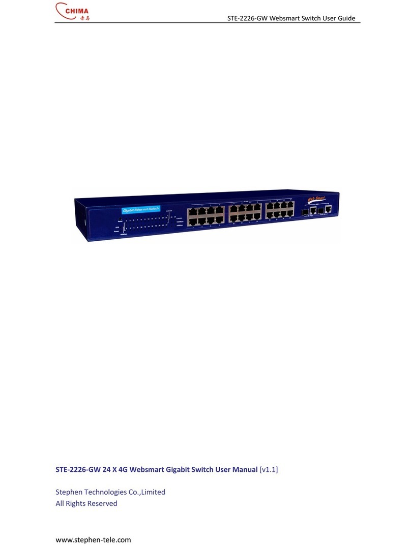
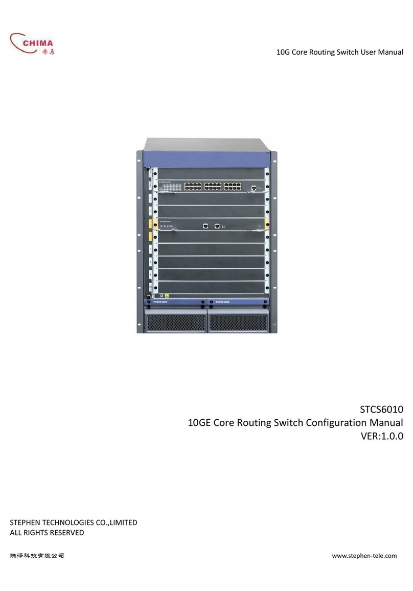
Chima STCS3526 Series User manual

STCS3526 Layer 3 Switch Installation Guide
www.stephen-tele.com
STCS3526 Series Routing Switches
Installation Guide Manual
ER:1.0.0
STEPHEN TECHNOLOGIES CO.,LIMITED
ALL RIGHTS RESER ED

STCS3526 Series Layer 3 Switch User Guide
www.stephen-tele.com
About This Manual
Release Notes
This manual applies to STCS3526 Series Routing Switches.
Related Manuals
The related manuals are listed in the following table.
《STCS3526 Series Routing Switches Installation Guide Manu》
《STCS3526 Series Routing Switches Configuration Guide Manu》
Intended Audience
The manual is intended for the following readers:
Network engineers
Network administrators
Customers who are familiar with network fundamentals
Conventions
The manual uses the following conventions:
I. General conventions
Convention Description
Arial Normal paragraphs are in Arial.
Arial Narrow Warnings, Cautions, Notes and Tips are in Arial Narrow.
Boldface Headings are in Boldface.
Courier New Terminal Display is in Courier New.
II. Command conventions
Convention
Description
Boldface
The keywords of a command line are in Boldface.
italic
Command arguments are in italic.
[ ]
Items (keywords or arguments) in square brackets [ ] are optional.
{ x | y | ... }
Alternative items are grouped in braces and separated by vertical bars. One is
selected.
[ x | y | ... ]
Optional alternative items are grouped in square brackets and separated by
vertical bars. One or none is selected.

STCS3526 Series Layer 3 Switch User Guide
www.stephen-tele.com
III. GUI conventions
Convention
Description
< >
Button names are inside angle brackets. For example, click the <OK> button.
[ ]
Window names, menu items, data table and field names are inside square
brackets. For example, pop up the [New User] window.
/
Multi-level menus are separated by forward slashes. For example,
[File/Create/Folder].
I . Keyboard operation
Format
Description
<Key>
Press the key with the key name inside angle brackets. For example, <Enter>,
<Tab>, <Backspace>, or <A>.
<Key1+Key2>
Press the keys concurrently. For example, <Ctrl+Alt+A>
means the three keys should be pressed concurrently.
<Key1, Key2>
Press the keys in turn. For example, <Alt, A> means the two
keys should be pressed in turn.
. Mouse operation
Action
Description
Click
Press the left button or right button quickly (left button bydefault).
Double Click
Press the left button twice continuously and quickly.
Drag
Press and hold the left button and drag it to a certain position.
I. Symbols
Eye-catching symbols are also used in the manual to highlight the points worthy of
special attention during the operation. They are defined as follows:
֠
֠֠
֠Caution: Means reader be extremely careful during the operation.
Note: Means a complementary description.

STCS3526 Series Layer 3 Switch User Guide
Chapter 1 Overview ..................................................................................................................... - 1 -
1.1 Brief Introduction ............................................................................................................ - 1 -
1.1.1 Hardware Architecture ......................................................................................... - 1 -
1.1.2 Services ................................................................................................................ - 1 -
1.2 Typical Application .......................................................................................................... - 2 -
1.2.1 Networking of Residential Area for Broadband Ethernet Access ......................... - 2 -
1.2.2 Networking of Medium/Small Enterprise or Large Enterprise Branch ................ - 2 -
1.2.3 Networking of Large Enterprise and Campus ...................................................... - 2 -
Chapter 2 Specifications and Features......................................................................................... - 3 -
2.1 Front Panel ...................................................................................................................... - 3 -
2.1.1 STCS3526A Front Panel ........................................................................................ - 3 -
2.1.2 STCS3526F Front Panel ......................................................................................... - 4 -
2.1.3 Fixed Ethernet Interface ...................................................................................... - 4 -
2.1.4 Interface Modules for STCS3526F ........................................................................ - 6 -
2.1.5 Types of Optional Interface Modules ................................................................... - 6 -
2.1.5.1 1000Base-SX/LX Module ........................................................................... - 7 -
2.1.5.2 1000Base-T Module .................................................................................. - 8 -
2.1.5.3 100Base-FX optical Module ...................................................................... - 9 -
2.1.5.4 Installation of the Optional Modules ...................................................... - 10 -
2.1.6 Console Port ....................................................................................................... - 11 -
2.1.7 AUX Port ............................................................................................................. - 11 -
2.2 Rear Panel ..................................................................................................................... - 12 -
2.2.1 STCS3526A real panel ......................................................................................... - 12 -
2.2.2 STCS3526A real panel ......................................................................................... - 12 -
2.3 Switch Performance ...................................................................................................... - 12 -
Chapter 3 Installation Preparation............................................................................................. - 14 -
3.1 Precautions ................................................................................................................... - 14 -
3.2 Requirements on Environment ..................................................................................... - 14 -
3.2.1 Temperature/Humidity Requirements ............................................................... - 14 -
3.2.2 Laser Safety ........................................................................................................ - 15 -
3.3 Installation Tools ........................................................................................................... - 15 -
Chapter 4 Installation................................................................................................................. - 16 -
4.1 Hardware Installation .................................................................................................... - 16 -
4.1.1 Installing the Switch in 19-inch Standard Cabinet ............................................. - 16 -
4.1.2 Installing the switch on the Workbench ............................................................ - 16 -
4.2 Connecting Power Cord ................................................................................................ - 16 -
4.3 Connecting Console Cable ............................................................................................ - 17 -
4.4 Connecting AUX Cable .................................................................................................. - 18 -
4.5 Post-installation Checklist ............................................................................................. - 18 -
Chapter 5 Booting and Configuration ........................................................................................ - 19 -
5.1 Setting up the Configuration Environment ................................................................... - 19 -
5.2 Connecting the Console Cable ...................................................................................... - 19 -
5.3 Setting Parameters of the Terminal .............................................................................. - 19 -
5.4 Booting Switch .............................................................................................................. - 21 -
5.4.1 Checking before Powered on ............................................................................. - 21 -
5.4.2 Powering on and Booting ................................................................................... - 21 -

STCS3526 Series Layer 3 Switch User Guide
- - 1 - -
Chapter 1 Overview
1.1 Brief Introduction
STCS3526 Series Ethernet Switches are a type of box-shaped L2/L3 wire speed Ethernet Switches, applied on the convergence layer
of the medium- and small-sized enterprise networks, IP Metropolitan Area Network (MAN) and Ethernet residential areas.
1.1.1 Hardware Architecture
STCS3526 Series Routing Switches Configurations include:
STCS3526A:24 10/100Mbps Ethernet ports and 2 extension slots
SPEED S6526F:6 modules slots and 2 extension slots
For STCS3526F, provide 2 types interface modules:
4-port 10/100Base-T Ethernet interface module
4-port 100Base-FX ports module
The extension slots can support the following modules:
1000Base-SX module
1000Base-LX module
1000Base-T module
100Base-FX Multi-mode module
100Base-FX Single Mode module
1.1.2 Services
Based on the SPROS Network OS, over which CHIMA has the independent intelligent property, STCS3526 Series Routing Switch can
provide various routing protocols, LAN management, traffic control and Qos guarantee etc., and it also provides perfect service
control and user management function.

STCS3526 Series Layer 3 Switch User Guide
- - 2 - -
STCS3526 Series Routing Switch supports online upgrade through various approaches such as FTP/TFTP. It also supports local
configuration and remote configuration.
1.2 Typical Application
STCS3526 Series Routing Switch can be used flexibly in different networking environment such as access to enterprise network and
broadband network. The following sections introduce some typical application cases of it.
1.2.1 Networking of Residential Area for Broadband Ethernet Access
In the networking of residential area with broadband Ethernet access, STCS3526 Series Routing Switch is located in the residential
area center. It connects to Ethernet users via the L2 switches such as SPEED S2026 Switch. Its Uplink is connected to the core L3
switch through the GE extended module and thus connected to the MAN backbone.
1.2.2 Networking of Medium/Small Enterprise or Large Enterprise Branch
In the medium/small enterprises or the branches of large enterprises, STCS3526 Series Routing Switch can serve as the backbone
switch, which is connected to the head office or other branches through the router. As the enterprise or organization scale grows,
STCS3526 Routing Switch can provide the larger scale backbone by cascade.
1.2.3 Networking of Large Enterprise and Campus
In large-scale enterprise networks and campus networks, STCS3526 Series Routing Switches are located on the convergence layer
and connected to several L2 Ethernet switches such as SPEED S2026 Switch on the downlink and the backbone GE switch via the GE
extended port on the uplink. In this way, STCS3526 Series Routing Switches provide a complete enterprise networking solution,
which provides 1000M bandwidth to backbone and 100M bandwidth to desktop users.

STCS3526 Series Layer 3 Switch User Guide
- - 3 - -
Chapter 2 Specifications and Features
2.1 Front Panel
2.1.1 STCS3526A Front Panel
There are 1 system led indicator, 1 Power led indicator, 1 pair of AUX Link/ACT led indicators, 24 pairs of Link/ACT led indicators, 24
fixed 10Base-T/100Base-TX Ethernet ports, 2 slots for optional modules, a Console port in sequence, 1 AUX port, in the front panel.
The table below describes the indicators on the front panel of STCS3526A Ethernet Switch.
Table 2-1 Front panel indicators
Indicator Sign State Meaning
Power indicator
PWR
On The switch is powered on.
Off The switch is powered off.
System status indicator STATUS
Off The switch is powered off
Blinking System work normally
AUX interface indicator
Active (Green)
Off
No data is being transmitted or
received.
Blinking
Data is being transmitted or
received.
Link (Green)
On Normal connection.
Off No connection
interface indicator
Active (Green)
Off
No data is being transmitted or
received.
Blinking
Data is being transmitted or
received
Link (Green)
On Normal connection.
Off No connection.

STCS3526 Series Layer 3 Switch User Guide
- - 4 - -
2.1.2 STCS3526F Front Panel
There are 1 system led indicator, 1 Power led indicator, 1 pair of AUX Link/ACT led indicators, 24 pairs of Link/ACT led indicators, 6
modules slots, 2 extension slots for optional modules, a Console port in sequence, 1 AUX port, in the front panel.
The table below describes the indicators on the front panel of STCS3526F Ethernet Switch.
Table 2-2 Front panel indicators
Indicator Sign State Meaning
Power indicator
PWR
On The switch is powered on.
Off The switch is powered off.
System status indicator STATUS
Off The switch is powered off
Blinking System work normally
AUX interface indicator
Active (Green)
Off
No data is being transmitted or
received.
Blinking
Data is being transmitted or
received.
Link (Green)
On Normal connection.
Off No connection
interface indicator
Active (Green)
Off
No data is being transmitted or
received.
Blinking
Data is being transmitted or
received
Link (Green)
On Normal connection.
Off No connection.
2.1.3 Fixed Ethernet Interface
On the front panel of STCS3526A, there are 24 Ethernet ports. The plug-in units are network connectors with indicators, matching
with RJ-45 network port connectors.

STCS3526 Series Layer 3 Switch User Guide
- - 5 - -
Table 2-2 Front panel Ethernet interface attributes
Attribute S3526 Ethernet Switch front panel
Connector type RJ-45
Connector number 24
Interface attributes
10M half/full duplex
100M half/full duplex
MDI/MDI-X auto-sensing
Standards complied with
IEEE 802.1P
IEEE 802.1Q
IEEE 802.1D
IEEE 802.3
IEEE 802.3u
IEEE 802.3x
Interface cable media and
maximum transmission
distance
Category 5 twisted pair, with a maximum transmission distance
of 100m.
Table 2-3 RJ-45 connector pinouts in MDI and MDI-X modes (10Base-T/100Base-TX)
Pin
MDI MDI-X
Signal Function Signal Function
1 Tx+
Transmitting
data
Rx+ Receiving data
2 Tx-
Transmitting
data
Rx- Receiving data
3 Rx+ Receiving data
Tx+
Transmitting
data
4 Reserved - Reserved -
5 Reserved - Reserved -
6 Rx- Receiving data
Tx-
Transmitting
data

STCS3526 Series Layer 3 Switch User Guide
- - 6 - -
7 Reserved - Reserved -
8 Reserved - Reserved -
Note:
Tx = Transmitting data
Rx = Receiving data
2.1.4 Interface Modules for STCS3526F
֠
֠֠
֠Caution:
Before installing or removing the optional interface modules, please make sure that the switch is
powered off to avoid damage to the components
Including flowing configurations:
4-port Ethernet 10/100Base-T interface module
4-port Ethernet 10/100Base-FX interface(SFP) module
2.1.5 Types of Optional Interface Modules
STCS3526 Ethernet Switch supports the following optional interface modules:
1-port 1000Base-SX module
1-port 1000Base-LX module
1-port 1000Base-T module
1-port 100Base-FX Multi-mode module
1-port 100Base-FX Single Mode module

STCS3526 Series Layer 3 Switch User Guide
- - 7 - -
2.1.5.1 1000Base-SX/LX Module
1000Base-SX module provides a GE multi-mode optical interface for users.
1000Base-LX module provides a GE single mode optical interfaces for users.
1000Base-SX/LX module interface matches SC connector.
The following table describes the meaning of the panel indicators.
Table 2-3 Meanings of indicators
Indicator Indicator state description
Link Off means that the line is not connected.
On means that the line is connected.
The following table describes the interface attributes of the 1000Base-SX/LX module.
Table 2-4 1000Base-SX/LX module interface attributes
Attribute Description
1000Base-LX module 1000Base-SX module
Connector type SC
Connector number 1
Cable and transmission
distance
9/125μm single-mode
fiber-optic cabling, with a
maximum transmission
distance of 10km
62.5/125μm multi-mode
fiber-optic cabling, with a
maximum transmission
distance of 550m
50 /125μm multi-mode
fiber-optic cabling, with a
maximum transmission
distance of 550m
62.5/125μm multi-mode
fiber-optic cabling, with a
maximum transmission
distance of 220m
50 /125μm multi-mode
fiber-optic cabling, with a
maximum transmission
distance of 500m

STCS3526 Series Layer 3 Switch User Guide
- - 8 - -
Standard complied with IEEE 802.3 z
Central wavelength 1300nm 850nm
Transmitting optical power >9.5dBm
Receiving sensitivity -20dBm -17dBm
Note:
When connecting the optical fiber, please pay attention to the following:
1) Do not bend the optical fiber excessively.
2) Do not wrongly connect the Tx and Rx ends of the modules.
3) Ensure cleanness at the interface of the optical fiber.
2.1.5.2 1000Base-T Module
1000Base-T module offers a 1000Base-T interface, working in full-duplex mode, supporting MDI/MDI-X auto-sensing and completely
compliant with the IEEE 802.3ab 1000Base-T criterion.
Table 2-5 1000Base-T module interface attributes
Attribute Description
Connector type RJ-45
Function 10/100/1000M full-duplex
Interface cable media and maximum
transmission distance
Category 5 twisted pair, with a maximum
transmission distance of 100m
The following table describes the meaning of the panel indicators.
Table 2-6 Meanings of indicators on 1000Base-T module
Indicator Indicator state description

STCS3526 Series Layer 3 Switch User Guide
- - 9 - -
Link Off means that the line is not connected.
On means that the line is connected.
Active Off means that no data is being received or transmitted.
Blinking means there is data being received and transmitted.
1000Base-T module interface matches RJ-45 connector, connected with 4 Category 5 non-shielded twisted pairs with RJ-45 plugs
and supporting a maximum transmission distance of 100m.
Table 2-7 RJ-45 connector pinouts in MDI and MDI-X modes (1000Base-T)
Pin
MDI MDI-X
Signal Function Signal Function
1 BIDA+ Bi-directional data wire A+
BIDB+ Bi-directional data wire B+
2 BIDA- Bi-directional data wire A-
BIDB- Bi-directional data wire B-
3 BIDB+ Bi-directional data wire B+
BIDA+ Bi-directional data wire A+
4 BIDC+ Bi-directional data wire C+
BIDD+ Bi-directional data wire D+
5 BIDC- Bi-directional data wire C- BIDD- Bi-directional data wire D-
6 BIDB- Bi-directional data wire B- BIDA- Bi-directional data wire A-
7 BIDD+ Bi-directional data wire D+
BIDC+ Bi-directional data wire C+
8 BIDD- Bi-directional data wire D-
BIDC- Bi-directional data wire C-
2.1.5.3 100Base-FX optical Module
100Base-FX Multi-mode module and 100Base-FX Single Mode module have the similar appearances and panels. 1000Base-FX
module interface matches SC connector.
The following table describes the meaning of the panel indicators.
Table 2-8 Meanings of indicators on 100Base-FX module
Indicator Indicator state description
Link Off means that the line is not connected.

STCS3526 Series Layer 3 Switch User Guide
- - 10 - -
On means that the line is connected.
Active Off means that no data is being received or
transmitted.
Blinking means there is data being received
and transmitted.
2.1.5.4 Installation of the Optional Modules
For the description of the functional module Installation, please refer to Chapter 3.
I. Installation Tools
Flat-blade screw-driver
ESD-preventive wrist strap
II. Installation Optional Modules
֠
֠֠
֠Caution:
Before performing any of the following operation, please make sure that the switch is powered
off to avoid damage to the components
Step 1: Wear ESD-preventive wrist strap and power off the switch.
Step 2: Face the rear panel of the switch.
Step 3: Hold the interface card of the functional module. Align the opposite side and angles with the edge of the opening in the rear
panel of the switch base.
Step 4: Push the interface card into the switch until it well contacts the rear panel.
Step 5: Tighten the fastening screws to the interface card of the functional module to the switch
III. Removal of optional interface modules
Step 1: Wear EDS-preventive wrist strap and power off the switch.
Step 2: Face the rear panel of the switch.
Step 3: Use a flat-blade screwdriver to loosen the captive installation screws.
Step 4: Pull the interface card toward yourself until release the whole card from the switch base.

STCS3526 Series Layer 3 Switch User Guide
- - 11 - -
֠
֠֠
֠Caution:
When removing the optional interface modules, pay attention to the following:
When removing /installing the module, do not apply too much force during the operation or
touch the components on the surface of the module
If the module is removed and there is no need to mount new one, mount the blank filler
panel in time to keep the dust out and ensure the normal ventilation of the switch
2.1.6 Console Port
The Console port complies with the EIA/TIA-232 asynchronous serial criterion. ia this port, Users can perform configuration locally
or remotely.
Table 2-9 Console port attributes
Attribute Description
Connector type RJ-45
Interface complying with Asynchronous EIA/TIA-232
Baud rate 9600bps ( by default)
Supported services
Connection with the character terminal
Connection with the local or remote PC serial port (through a pair of
Modems when connected remotely) and the execution of terminal
simulator on PC.
2.1.7 AUX Port
The AUX port is an assistant management port . ia this port, Users can perform configuration locally or remotely trough telnet or
web management.

STCS3526 Series Layer 3 Switch User Guide
- - 12 - -
2.2 Rear Panel
2.2.1 STCS3526A real panel
On the rear panel of switch there are a AC power input socket and the power switch.
2.2.2 STCS3526A real panel
On the rear panel of switch there are 2 extensions slots 、a AC power input socket and the power switch.
2.3 Switch Performance
Table 2-10 STCS3526 Routing Switches Specification and Performance
Feature STCS3526A STCS3526F
Port Configuration
24 10Base-T/100Base-TX
Ethernet ports
2 extension slots for
optional modules
6 modules slots
2 extension slots for
optional modules
Switching Capacity 8.8G
Packet Forward Capability 6.6Mpps
Power Consumption <30W
Basic Performance
MAC Address Table 8K
Routing Table Entries 2K
Buffer Capacity Shared 32M
Forwarding Mode Store-and-forward
Network and Flow Control
P LAN Yes
LAN 802.1Q 4k
QoS 4 priority queues for each port
Queue Dispatching Methods WRR、SP

STCS3526 Series Layer 3 Switch User Guide
- - 13 - -
Port Convergence Supports FE, GE port convergence; maximum 6 groups with
8 ports at most in each group
Routing Protocols
Unicast Static Routing, RIP 1/ 2, OSPF 2,
Multicast IGMP, PIM-SM,
Policy Routing Yes
QoS routing Yes
Num of Routing Interfaces 256
Security Feature
802.1X Yes
PORTAL Yes
STP Yes
ACL 1K
MAC address limitation Yes
Broadcast Strom Suppression
Yes
CPU Protection Yes
Management Features
SNMP SNMP 1 / 2c
RMON 1、2、3、9
HTTP Yes
CLI Yes
Dimension (L*W *H) 443mm×360mm×44.5mm 443 ㎜×280 ㎜×66.7 ㎜
Working Environment 0~40 °C 10~90% non-condensing
Weight <6.5Kg <6.5Kg

STCS3526 Series Layer 3 Switch User Guide
- - 14 - -
Chapter 3 Installation Preparation
3.1 Precautions
To avoid any device impairment and bodily injury due to improper use, please follow the precautions listed below:
Before cleaning the switch, please unplug the switch connector first. Do not clean the switch with wet cloth or with liquid.
Do not place the switch near water or any damp area. Try as much as possible to prevent water and moisture from entering the
switch chassis.
Do not place the switch on the unstable cases or desktop, as the switch might be damaged severely in case of a fall.
Ensure proper ventilation of the room and keep the switch ventilation hole free of obstruction.
The switch can operate normally under correct voltage input. Make sure that the operating voltage is consistent with that
labeled on the switch.
Do not open the chassis while the switch is in operation to protect the safe of the operator and the switch.
3.2 Requirements on Environment
Switch should be used indoors. The following requirements must be met irrespective of whether you install the switch in 19-inch
standard cabinet or install it directly on the workbench.
Make sure that enough room is left for the ventilation hole of the switch so as to ensure the heat dissipation of the switch
chassis.
Make sure that the drafting and heat dissipation systems of the cabinet and the workbench are good.
Make sure that the cabinet and the workbench are stable enough to bear the weight of the switch and the accessories.
Make sure that the cabinet and the workbench are well grounded.
To ensure normal operation and prolong the service life of the switch, the requirements on the installation site described in the
following sections must also be met.
3.2.1 Temperature/Humidity Requirements
To ensure the normal operation and service life of a switch, you need to maintain the temperature and the humidity of the
equipment room at a certain level. If the humidity level in the equipment room is too high for a long time, it will lead to bad
insulation of the insulating material or even leakage. Sometimes, the mechanical performance, change of material and the corrosion

STCS3526 Series Layer 3 Switch User Guide
- - 15 - -
of some metal parts are also likely to occur. If the relative humidity is too low, the captive screw may become loose due to the
shrinking of insulating sheath. Meanwhile, the static electricity is likely to be produced in the dry weather, which may jeopardize the
CMOS circuit of the switch. The Higher the temperature is, the greater the damage to the switch will be. The reliability of the switch
will be then seriously affected and its service span will be shortened because of exposure to high-temperature environment for a
long term. The ultra-high temperature will speed up the aging process of the insulating material.
3.2.2 Laser Safety
In operating status, it is prohibited to stare into the open optical interface because the laser being transmitted through the optical
fiber will produces a small beam of light, it has very high power density and is invisible to human eyes, when a beam of light enters
the eye, retinal may be burned.
֠
֠֠
֠Caution:
Staring at the laser beam inside the fiber could hurt your eyes.
3.3 Installation Tools
Phillips screwdriver
Flat-blade screwdriver
ESD-preventive wrist strap
Note:
The installation tools are not shipped with Switch. Please prepare beforehand

STCS3526 Series Layer 3 Switch User Guide
- - 16 - -
Chapter 4 Installation
4.1 Hardware Installation
4.1.1 Installing the Switch in 19-inch Standard Cabinet
Take the following steps to install the switch:
Step 1: Check the grounding and stability of the cabinet. Attach the angle iron at both sides of the front or rear panel with screws.
Step 2: Place Switch on a shelf of the cabinet. In accordance with the actual cases, slide switch along the guiding slots of the cabinet
to an appropriate position. Ensure that there is proper clearance between the Switch and the guides.
Step 3: Use screws to attach the angle iron on the fixed cable guides at both sides of the cabinet. Make sure that switch is securely
mounted on the cabinet with the brackets of cabinet slots and the mounting angle iron of the switch.
4.1.2 Installing the switch on the Workbench
If 19-inch standard cabinet is not available, you may simply place the switch on a clean workbench. However, you need to pay
attention to the followings during such operation:
Make sure that the workbench is stable and well grounded.
Leave about 10 centimeters away from the four sides of the switch for heat dissipation.
Do not place heavy objects on top of the switch.
4.2 Connecting Power Cord
Step 1: Connect one end of the ground wire of the chassis shipped with the switch to the grounding screw on the switch rear panel,
and properly ground the other end as near as possible.
Step 2: Plug one end of the power cord to the power socket on the rear panel of the switch chassis, and plug the other end into the
socket of AC power supply.
Step 3: Check whether the power indicator (POWER) on the front panel of the switch is on. On means that the power cord is
correctly connected.
This manual suits for next models
1
Table of contents
Other Chima Switch manuals
Popular Switch manuals by other brands
Ocean Matrix
Ocean Matrix OMX-5009A instruction manual
Oracle
Oracle Sun Datacenter InfiniBand Switch 648 installation guide
TRENDnet
TRENDnet TE100-S800i Specifications
Omnitron Systems Technology
Omnitron Systems Technology OmniConverter 10GPoE+/M quick start guide

Force 10
Force 10 C300 Installing and maintaining
H3C
H3C S3100V2 Series Installation, quick start

