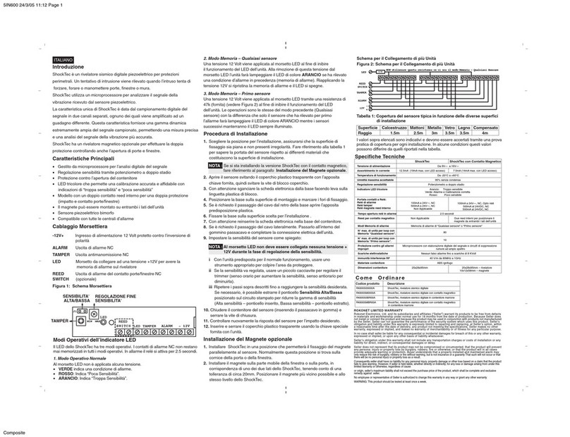
6. WIRE UP THE TERMINAL
9. TESTING and Pulse Set
Even the most sophisticated detcetors can sometimes be defeated or may fail to warn due to :DC power failure/improper connec-
tion, malicious masking of the lens,tampering with the optical system, decreased sensitivity in ambient temperatures near that
of the human body and unexpected failure of a component part.The above list includes the most common reasons for failure
recommended that the detector and the entire alarm system be checked weekly, to ensure proper performance.
An alarm system should not be regarded as a substitute for insurance. Home & property owners or renters shouldbe prudent enough to
continue insuring their lives & property, even though they are protected by an alarm system.
This device has been tested and found to comply with the limits for a Class B digital device, pursuant harmful interference in resi-
dential installations .This equipment generates,uses and can radiate radio frequency energy and ,if not installed and used in acco-
rdance with the ins-tructions ,may cause harmful in-terference to radio and television reception. However, there is no guarantee that
interference will not occur in aparticular installation .If this device does cause such interference , which can be verfied by turning
the device off and on ,the user is encoura-ged to eliminate the interference by one or more of the follow ingmeasures:
- Increase the distance between the device and the receiver.
- Connect the device to an outlet on a circuit different from the one that supplies power to the receiver.
- Consult the dealer or an expericnced radio/TV technician.
10. NOTES AND WARNINGS
WARNING! Changes or modifications to this unit not expressly approved by the party responsible for compliance could void the
user s authority to operate the equipment.
+
-
ZONE
USING AN E.O.L.
RES I STO R WHEN THE
CONTROL PANEL ISSET
FOR E.O.L.OPERATION
ALARM CONTROL PANEL
24-H
ZONE
12VDC
OUT
ZONE
EOL RESISTO R
ALARM
3P
Note: The maximum pulse count for the long range and curtain
lenses is 2P. It is not recommended to select 3P for dis-
tances above 12m
Figure 7
Please face the position with indentation on the upper cover to that
on the lower cover, press and rotate the covers clockwise to close it
Tation
Figure 9
8. CLOSE THC EXTERNAL COVERS
2P
1 2 34
Factory default
Crossing 2 beams
causes detection
Crossing 3 beams
causes detection
For excellent false
alarm protection
For maximum
false alarm
protection
in hostile
environment
Figure 10
TAMPER
+ 12V - ALARM
- 12V + : 9~16V DC power supply
ALARM : Zone input of control panel (N.C/N.O)
TAMPER: 24 hours N.C. loop of control panel
TAMPER
+12V-
ALARM
N.C N.O
The alarm output can be charged to N.O by removing the jumper
from N.C/N.O selector. N.O output can be ap p l ied t o ac t i vate
VCR of CCTV systems or other equipment.
7.ALARM OUTPUT SELECTOR
The Sensor an intelligent pulse count that reduces the possibi-
lity of false alarm caused by environmental and power line inter-
ference. T he pulse count can be set to count 2 or 3 pulses by
placing the jumper head on the corresponding pins. An alarm
signal will only be sent when the selected pulses are generated
within delay time of 20 seconds. SEC-TEC's intelligent pulse
count circuitry analyzes the width difference of pulse signal.
When h uman motion is detected a subsequ ent pulse s ig na l
will over-ride the pulse count setting andgenerate the alarm
signal without any delay. P.C
P.C
Note:Verify correct operation of the detector by conducting
a walk test at least once a year.
2010-25 REV00
Figure 6
Figure 8
