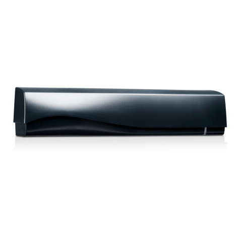
ChinaPST PST Series User manual

MANUAL FOR INFRARED BALUSTER
Esteemed customers, thank you very much for purchasing
our products "HM" series infrared burglarproof baluster.
In order to use our product properly, please read the
booklet carefully beforeoperating the product.
1.SUMMARY
This indoor /outdoor available Multi-beams positive
infrared burglarproof baluster is anadvanced
intelligentize Hi-Tech product. With the features of
simple installation, easydebugging, aesthetic appearance,
etc. It can be installed in fences, doors, windows,
balconys, and which place should be prevented from
burglars, to protect your safety and properties. The
product is widelysuitable for thesafety of residential
house, villas, factories,schools, office building, etc.
2.PERFORMANCE
2.1 Intelligent judgment: when the theft comes into the
protective zone, andblock two ormore infrared beams
which over 40mswill give outthe alarm. Itcan effectively
prevent the traditionaldeficiencies of falsealarm.
2.2 Identify object: can distinguish the size of the
traversing object automatically. When the lawless
intruder coming, it will give out alarm. But it doesn't work
when the intruder is a cat or a dog.
2.3 High reliabilities:Anti-cutting, anti-interference
technology. Prevent the intruder adopts destroy method or
gives false signal.
2.4 Rainproof /Moistureproof:Rainproof structure,
available for outdooror damp place.
2.5 Pretty structure: The main outer shell adopts superior
aluminous alloy materials,and the exterioradopts plastic
spray processing, firmand durable. Importedoptical filter
to block motleylight.
2.6 Easy for installation & debugging: After fixing the
installation seat, the angle of transmitting /receiving
infrared beams canbe circumvolved 360freely.
2.7 Protective grade adjustable: Can be set as different
protective grade accordingto user's requirement.Strict
grade and ordinarygrade optional.
3.PARTS NAME
4.INSTALLATION METHOD
4.3 Drill holeson the installationinterface with 6
aiguille, drive into the plastic post, then fix the
installation seat withM4 tapping screws.
4.4 Make surethe transmitter andthe receiver aimat each
other. While connect with power supply, the power
indicator of the transmitter shows green light, and the
work indicator showsred intermittent flash.After the both
parts aim at each other, the red light of the receiver turn
off, and the buzzer stop buzzing. In case there are
something lighttight blockany neighboring 2beams
simultaneously, the indicator of the receiver shows red
intermittent flash, and the buzzer start to buzz, the
detector give outwired /wireless alarmsignal.
It's the bestto adjust angleof the detectorin the bad
climate, like in the situation of fierce sunlight or fog.
4.5 Tighten the screws in the installation seat of the
transmitter and the receiver, then cover the protective
cover, thewhole operation is ok.
4.6 The receiver will giveout wired /wireless alarm signal
at the situation as following;
4.6.1 There are something blockany neighboring 2 beams
simultaneously.
4.6.2 Disconnect power supply of the transmitter or the
receiver (cut off the power cord by man-made).
4.6.3 Move the position /orientation of the transmitter or
the receiver.
Note:
In order to prevent false alarm result of public power off,
we suggest theuser select UPSas power supply, which
means it willprocess float charging when thepublic
power is onthe rails, andit will alternate automatically as
powered by UPSwhile the publicpower off. It is
forbidden to useinferior non-linear switchingpower
supply.
In order tomake full usagewith the infraredbaluster.
Please select thecondign model accordingto the practical
guard range.
Avoid the irradiation ofsharp light, lamplightor other
strong light.
Keep the outer shield cleaning for fear influence the
work of the detector.
4.1 Fix on the position for installation, make sure the
infrared beams canblock the objectivepassage effectively.
Keep the transmitterand the receiverare parallel andaim
at each other.
4.2 Break downthe threading holein the installationseat
with some pointedinstruments, like thescrewdriver.
Make the power cord through the threading hole of the
installation seat, then through the threading hole of the
down-lead seat. Finally, connect the power cord with the
power terminal according to "+" and "-".
1
1. Protective cover
2. Installation seat
3. Down-lead seat
4. Anti-dismantle reed switch
5. Infrared lens
6. Section steel pole
7. Derivative line
"PST"

MANUAL FOR INFRARED BALUSTER
5.1 Instruction forthe Receiver part
5.1.1 SW:The down-lead seat to be installed normally, the
two terminals ofthe anti-dismantle reedswitch is
NORMAL CLOSE. And it becomes as NORMAL OPEN
while the down-leadseat to bedrawn out.
5.1.2 +: DC12Vpositive pole
5.1.3 -: DC12Vnegative pole
5.1.4 To: Please refer to the Transmitter part TO
5.1.5 COM: Relayoutput public terminal
5.1.6 NC: Relay output normal close (working)
5.1.7 NO: Relay output normal open (working)
5.2 Instruction forthe slip stitch:
5.2.1 Buzzer slipstitch: "BEAP" shortcircuit with "NO",
the buzzer giveout alarm.And connect with"OFF", it's
silent;
5.2.2 Wireless control slipstitch: "REMOT" connect with
"NO" is routineusage, and shortcircuit with "TEST"
becomes testing status,be master ofwireless normal open
or normal close;
5.2.3 Wireless test slipstitch: "TEST" short circuit with
"NO" is normalopen, and connectwith "OFF" becomes
normal close;
5.2.4 Code slipstitch: It's usedfor High FrequencyCode,
district A is Date Code, the others are Address Code (row
L islow, row H is high).
5.3 Instruction for the Transmitterpart:
5.3.1 SW:The down-lead seat to be installed normally, the
two terminals ofthe anti-dismantle reedswitch is
NORMAL CLOSE. And it becomes as NORMAL OPEN
while the down-leadseat to bedrawn out.
6. TECHNICAL PARAMETER
2
5. INNER CONNECTION
Beam of light 246810
3
Beams Beams Beams Beams Beams Beams
Validlength (cm)
Detector length (cm)
Weight (kg)
28 45 63 116 158 200
36 53 71 124 166 208
0.48 0.58 0.68 1.08 1.58 1.98
Max. Static
current (mA)
Transmitter
Receiver
160
Standby current (mA) 45 50 55 60 65 70
Guard distance (m)
10 10 10 10 10 10
20 20 20 20 20 20
30 30 30 30 30 30
40 40 40 40 40 40
Power supply DC 12-18V
Alarm output Wired orwireless
Relay contact capacity
Trigger time 40ms
Response speed Open time 1.5s
Adjustable angle Horizontal;180 ( 90 )
Environmental condition Temperature: -35 +55
3A /125VAC /5VDC 0.2W
5.3.2 Transmitting distance terminal: Connect with
"LOW" is short distance, "MID" is middle distance, and
"FAR" is long distance;
5.3.3 +; DC12Vpositive pole
5.3.4 -; DC12Vnegative pole
5.3.5 TO; Connect "TO" of the two parts (Transmitter part
and Receiver part) with lead, and connect their negative
pole. Then, the detector goes into strict protection mode
(Be able to against vicious High-intelligent breakage);
Disconnect them, the detector is at general protection
mode(Strong anti-interference function, easy for
connection). It willgive out alarmsignal immediately in
case its connectionlead being cutby someone.
Special attention:
When the infrared baluster of 6,8,10 beams to be
installed within a range of less than 10 m, It should be
made as strictprotective mode. So,please keep some
place for the TO line and the earth line during construction
and installation.
In order to avoid false alarm or fail to alarm, the
transmitting distance terminal should connect with "FAR"
while the detector works in the atrocious outdoor
circumstance. Only atthe status ofthe reflecting signalis
too intense to alarm, it connect with the LOW , for
fear the reflectionresult in falsealarm.
This manual suits for next models
10
Other ChinaPST Security Sensor manuals
Popular Security Sensor manuals by other brands
Aspectek
Aspectek YARD SENTINEL product manual
Theben
Theben PlanoCentro 000-E Series operating manual

Franke
Franke 2030019212 Installation and operating instructions
Tecnoalarm
Tecnoalarm INFROTEK MASK quick guide
Datalogic
Datalogic Smart-VS Plus Product reference guide

PCB Piezotronics
PCB Piezotronics W138A01/-0021 Installation and operating manual

