CHINT NP2 Series Installation instructions

NO:2020.04
Standard:IEC/EN 60947-5-1
NP2 Series
Pushbutton
User Instruction
Safety Warning
1
2
3
4
Only professional technicians are allowed for installation and
maintenance.
Installation in any damp, condensed-phase environment with
inflammable and explosive gas is forbidden.
When the product is being installed or maintained, the power
must be switched off.
You are prohibited from touching the conductive part when
the product is operating.

1
2
01
NP2 series pushbutton is used in industrial control circuit with frequency
of AC 50Hz or 60Hz, rated operating voltage up to 415V and DC operating
voltage up to 250V. It is used to control electromagnetic starter, contactor,
relay and other electrical circuits. Pushbutton with indicator is also suitable
for applications that need signal light indication.
Use Purpose
Main Technical Parameters
Table 1 Main technical parameters
Environmental
conditions
Ambient temp. (℃)
Hot and humid
atmospheric conditions
Altitude
Pollution class/
installation category
Rated operating voltage
Ue(V)
Rated operating current
Ie(mA)
Rated insulation voltage
Ui(V)
Conventional thermal
current Ith(A)
Rated impulse withstand
voltage Uimp(kV)
Head protection class
Rated operating voltage
of button with indicator
Ue(V)
Technical parameters
-5℃~+40℃, average temperature should
not exceed +35℃ within 24h
Relative humidity should not exceed 50% at +40℃;
up to 90% at +20℃;
No influence below 2000m
Class 3/II
AC-15: 415/380/240/220; DC-13: 250/220/125/110
415
10
2.5
IP40, IP65 (part)
See product body for details
AC-15: 1.9/2.5/3/4.5; DC-13: 0.27/0.3/0.55/0.6
Rated operating current
of button with indicator
Ie(mA)
See product body for details
02
3
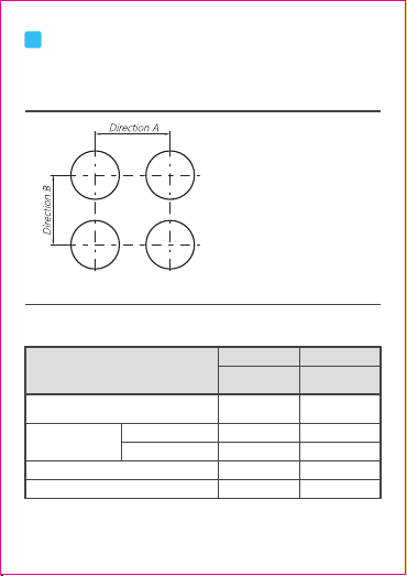
Installation
1) See Figure 1 and Table 2 for minimum distance between the center of
mounting holes. See Table 3 for installation dimensions of button control
box.
Figure 1 Minimum distance between center of mounting hole
Table 2 Minimum distance between center of mounting hole
Unit:mm
The diameter of the mounting hole for
+0.4
Φ22 panel mounting button is 22.3 0
mm; the metal head is suitable for
mounting panel with thickness of
1mm~6mm; the plastic head is suitable
for mounting panel with thickness of
1mm~4mm.
Type
Flat type, knob type, handle type,
key type, with indicator, signal light
Φ22 installation
dimensions
Φ22 installation
dimensions
Direction A Direction B
Mushroom type,
self- locking type
Dual head button
Dual head button with indicator
Φ30 Φ40
Φ60
30
30
65
30
30
50
50
65
50
60
03
Table 3 Installation dimensions of button control box
Unit:mm
Model
NP2-B1□□□□□
NP2-B2□□□□
NP2-B3□□□□□
Cable hole size Installation dimensions
Φ
Φ20
Φ20
20 2-Φ4.3, center to center distance 54
2-Φ4.3, center to center distance 54×68
2-Φ4.3, center to center distance 54×98
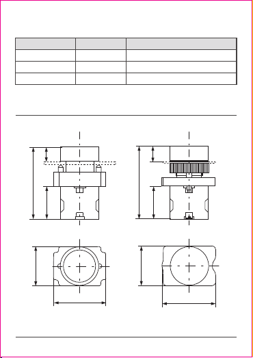
2) See Figure 2 and Figure 3 and Table 4 and Table 5 for product overall
dimensions.
DD
A
B
C
25
C A
B
25
Figure 2 NP2-BA□□ Figure 3 NP2-EA□□
Unit:mm

04
Table 4 Overall dimensions of different types of pushbuttons
Unit:mm
Model
NP2-BA□□ NP2-EA□□
NP2-BC□□/ NP2-EC□□
NP2-BS□□□/ NP2-ES□□□
NP2-BT□□/ NP2-BX□□
NP2-BD□□/ NP2-ED□□
NP2-BJ□□/ NP2-EJ□□
NP2-BG□□/ NP2-EG□□
NP2-BL8□□□/ NP2-EL8□□□
NP2-BW3□6□/ NP2-EW3□6□
NP2-BW3□8□/ NP2-EW3□8□
NP2-BW8□6□/ NP2-EW8□6□
NP2-BV6□/ NP2-EV6□
NP2-BV8□/ NP2-EV8□
/
A B C D
55/55
75/75
75/75
75/75
71/71
71/71
63/63
55/55
80/80
86/86
78/78
56/56
56/58
13/12
33/33
33/33
33/33
27/27
27/27
27(19)/27(19)
12/12
19/19
19/19
15/15
14/17
14/17
30/30
40/40
40/40
31/31
31/31
31/31
31/31
30/30
30/30
30/30
30/30
30/30
30/30
40/42
40/42
40/42
41/41
41/41
41/41
41/41
42/42
40/42
40/42
55/55
40/42
40/42
Note: For NP2-BG□□ NP2-EG□□B, the dimension outside the brackets is height
with key, the dimension inside the brackets is height without key.
/
Table 5 Overall dimensions of pushbutton control box
Unit:mm
Model
NP2-B1□□□□□
NP2-B2□□□□
NP2-B3□□□□□
Length Width Height Remarks
70
105
135
70
70
70
63
63
63
Height for empty case 52
Height for empty case 52
Height for empty case 52

Terminal tightening
torque N.m
M3.5
0.8 1.2~
Wire (Hard)
mm²
Wire (Soft)
mm² Remarks
1) Use hard wire or
soft wire for a single
connection.
One terminal can
connect up to two
conductors with
same sectional area
and type;
2) Wire strip length:
8mm.
8mm
8mm
2×
(0.5 2.5)~
2×
(0.5 2.5)~
05
3) See Table 6 for wire selection and tightening torque
Table 6 Wire selection and tightening torque
4) Installation procedure and method
① When installing metal head type button, insert the operation head
into the mounting hole from the front of the panel, then screw it into the
base from the back of the panel. Tighten the fixing screws at both ends
evenly (as shown in Figure 4). Do not overtighten the screws, the torque
should not exceed 0.25N·m. If the button is jammed after installation, adjust
the two fixing screws on the base and make sure they have the same
tightness.
②Before installing plastic head type button, remove the base first (insert
a screwdriver into the hole on the base and pry it up, as shown in Figure 5).
Tighten the nuts with a torque of 1.2N·m~1.8N·m.
③For NP2-B□□□□ NP2-J□□□□ buttons with cases, there are two
Φ21mm cable holes on both sides of their bottom covers. Before
installation, user should perforate the cable hole as needed (do not use too
much force). If IP40 is required for overall enclosure protection, user should
pay attention to the protection of the cable holes and the screw holes on
bottom cover. The cable holes can be protected by using cable connectors
with matching specifications or other effective measures. The tightening
torque for the installation of button box case should not exceed 1.2N·m.
,

06
4
Maintenance
Tighten the terminals of the button on a regular basis to make sure the
wires are connected securely.
Tighten the fixing screws of the button on a regular basis.
Disconnect the power before regular maintenance to ensure personal
safety.
It is recommended to conduct maintenance once a month.
See Table 7 for Analysis and Troubleshooting of Faults.
Figure 4 Assembly diagram of
metal head type base
Figure 5 Disassembly diagram of
plastic head type base
Table 7 Analysis and Troubleshooting of Faults
Symptons Cause analysis Troubleshooting method and precautions
The button
cannot be
operated
smoothly
There are foreign objects
like dust or greasy dirt
on the button operation
head or pushing rod of
contact assembly.
Remove the foreign objects like dust or greasy
dirt on the button operation head or pushing
rod of contact assembly, make sure the
environment is dry and clean after installing
the panel. Use proper lubricant at the moving
surface of the parts if necessary.
Check if the input voltage complies with the
rated operating voltage; check if there is any
short circuit or disconnection in the circuit.
The input voltage does
not comply with the rated
operating voltage, or
there is short circuit or
disconnection in the circuit.
The light
bead is not
bright
enough or is
not on at all
QC PASS
Test date: Please see the packing
ZHEJIANG CHINT ELECTRICS CO., LTD.
NP2 Series
Pushbutton
IEC/EN 60947-5-1
Check 31
07
In order to protect the environment, the product or product parts
should be disposed of according to the industrial waste treatment process,
or be sent to the recycling station for assortment, dismantling and recycling
according to local regulations.
5
Environmental Protection

NP2 Series
Pushbutton
User Instruction
Zhejiang Chint Electrics Co., Ltd.
Add: No.1, CHINT Road, CHINT Industrial Zone,North Baixiang,
Yueqing, Zhejiang 325603,P.R.China
E-mail: global-sales@chint.com
Website: http://en.chint.com
This manual suits for next models
3
Table of contents


