Simpro MegaDumper User manual

User Manual // Simpro MegaDumper®
Original Instructions // English // v86.0 // February 2022
USER MANUAL

Copyright © 2022 Simpro Handling Equipment Ltd.
No part of this document may be reproduced or transmitted in any form or by any means,
electronic, mechanical, photocopying, recording, or otherwise, without the written
permission of Simpro Handling Equipment Ltd.
For the purposes of standards compliance and international conformity, this document uses
Système International (SI) units. These may be converted to Imperial units as follows:
1 kilogram (kg) = 2.2 pounds (lb)
1 metre (m) = 1000 millimetres (mm) = 39.37 inches (in) = 3.28 feet (ft) = 1.09 yards (yd)
The following stylistic conventions are used throughout this document:
Point of interest
Point of warning
§Internal cross-reference (hyperlink in PDF edition)
Simpro partcode (hyperlink in PDF edition)
Errors in this document should be reported to info@simpro.world

User Manual // Simpro MegaDumper®
Original Instructions // English // v86.0 // February 2022 // Page 2

Contents
1. Product Overview ......................................................................................................................... 5
1.1 Key features ......................................................................................................................................... 5
1.2 Construction ........................................................................................................................................ 6
1.3 Mechanism .......................................................................................................................................... 6
1.4 Safe Lifting Capacity .......................................................................................................................... 6
1.5 Duty cycle ............................................................................................................................................ 6
1.6 Service life ............................................................................................................................................ 7
1.7 Noise emissions .................................................................................................................................... 7
1.8 Environmental restrictions ................................................................................................................... 7
1.9 Ingress protection................................................................................................................................ 7
1.10 Notes..................................................................................................................................................... 8
2. Operating Instructions .................................................................................................................. 9
2.1 Before use ............................................................................................................................................ 9
2.2 Emplacing and removing bins........................................................................................................... 9
Cradle identification........................................................................................................................................9
Type-S and Type-E Cradles............................................................................................................................ 11
Type-C Cradle ................................................................................................................................................ 11
Type-M and Type-N Cradles.......................................................................................................................... 12
Type-X (Custom) Cradle ................................................................................................................................12
2.3 Operating the controls ..................................................................................................................... 13
Control Panel identification...........................................................................................................................13
Standard Control Panel ................................................................................................................................. 14
Autocycle Control Panel ...............................................................................................................................14
VSD Control Panel.......................................................................................................................................... 15
Safety-Monitored Control Panel ................................................................................................................... 15
3. Safety Information.......................................................................................................................17
3.1 Safety features................................................................................................................................... 17
3.2 Reasonably foreseeable misuse ...................................................................................................... 17
3.3 ISO12100 Hazard and Risk Assessment Guide ................................................................................ 17
3.4 ISO13849 Conformance Guide........................................................................................................ 23
3.5 Safety Norms...................................................................................................................................... 25
4. Care and Maintenance.............................................................................................................27
4.1 Quick Troubleshooting Guide .......................................................................................................... 27
4.2 Cleaning............................................................................................................................................. 28
4.3 Cradle adjustment ............................................................................................................................ 28
4.4 Cradle jams........................................................................................................................................ 31
4.5 Electrical System (battery)................................................................................................................ 33

User Manual // Simpro MegaDumper®
Original Instructions // English // v86.0 // February 2022 // Page 4
International conformance...........................................................................................................................33
Voltmeter ........................................................................................................................................................33
Batteries ..........................................................................................................................................................34
Battery charger .............................................................................................................................................. 34
Battery box ..................................................................................................................................................... 34
Appliance inlet ............................................................................................................................................... 35
Isolator switch ................................................................................................................................................. 35
Circuit breaker................................................................................................................................................ 35
Solar panel kit ................................................................................................................................................. 35
4.6 Electrical System (3-phase mains) ................................................................................................... 36
International conformance...........................................................................................................................36
Appliance inlet ............................................................................................................................................... 37
Isolator switch ................................................................................................................................................. 37
Power supply unit ........................................................................................................................................... 37
4.7 Electrical System (1-phase mains) ................................................................................................... 37
International conformance...........................................................................................................................37
Appliance inlet ............................................................................................................................................... 37
Isolator switch ................................................................................................................................................. 38
Transformer .....................................................................................................................................................38
Variable Speed Drive..................................................................................................................................... 38
4.8 Hydraulic System ............................................................................................................................... 38
Powerpack .....................................................................................................................................................38
Control valves................................................................................................................................................. 38
Lift rams ...........................................................................................................................................................39
Hydraulic fluid................................................................................................................................................. 39
Maintenance.................................................................................................................................................. 39
Hydraulic system schematic.......................................................................................................................... 39
4.9 Safety Door and Interlock System.................................................................................................... 40
4.10 Safety-Monitoring System (CAT3/CAT4 only).................................................................................. 43
5. Assembly, Handling, Transport & Storage ................................................................................ 43
6. Preventative Maintenance Inspections ................................................................................... 45
6.1 Pre-inspection checklist .................................................................................................................... 45
6.2 Weekly inspection ............................................................................................................................. 45
6.3 Monthly inspection............................................................................................................................ 49
6.4 Annual inspection ............................................................................................................................. 51
7. Spare Parts ................................................................................................................................... 53
8. Warranty....................................................................................................................................... 55
9. EC Declaration of Conformity ................................................................................................... 57
10. Notes............................................................................................................................................. 58

1. Product Overview
Congratulations on your purchase of a Simpro
MegaDumper® bin-tipping machine. Since its
introduction in 1998, the MegaDumper has
established a reputation as the safest and most
reliable high-throughput bin lifter available.
With a modular design, the MegaDumper is
suitable for many different
applications from emptying
rubbish into compactors, to
pouring ingredients into mixers.
No matter how it is used, the
MegaDumper has proven to be
safe, economical, and easy to
operate, year after year.
1.1 Key features
Key features of the MegaDumper include:
1. A unique tipping action whereby bins are
lifted straight up, and then gently rolled
forward around the lip of the receptacle
being emptied into. Benefits of this design
and a wide range of tipping heights, from
900mm to more than six metres.
2. A standard lifting capacity of 600kg.
3. A reliable electro-hydraulic mechanism
which requires very little maintenance.
4. A hot-dip galvanised frame and cradle.
5. A versatile cradle system which lifts many
common waste bins without modification,
clamping or retaining. The standard Type-E
cradle lifts EN840 wheelie bins from the
base, avoiding damage to the
combing and extending bin life.
6. A modular design which can be easily
adapted to unique requirements, including
non-standard bins, tipping heights and
power supplies.

User Manual // Simpro MegaDumper®
Original Instructions // English // v86.0 // February 2022 // Page 6
1.2 Construction
The MegaDumper consists of a steel frame with two vertical masts and stabilizing legs, a bin
cradle, two hydraulic rams, lifting chains, guarding, powerpack cover, control panel, castor
wheels, power lead or batteries, hydraulic powerpack and electronic control systems.
1.3 Mechanism
When the RAISE button is pressed, two hydraulic rams are extended, which pull on an
arrangement of chains, causing the bin cradle to travel vertically in the masts. The cradle is
inverted at the appropriate height by an arrangement of arms, rollers, and curved tracks.
The rams are supplied by a hydraulic pump, which may be driven by a 3-phase, 1-phase,
battery, or compressed-air motor. Electrical, hydraulic, and mechanical control systems allow
the operator to lift and lower the bin in a controlled manner.
1.4 Safe Lifting Capacity
The Safe Lifting Capacity of the standard MegaDumper is 600kg (550lb).
Some machines may be specified with different capacities. Refer to the rating plate to verify
the Safe Lifting Capacity on any given machine.
Safe Lifting Capacity is a gross figure, referring to the weight of the bin, its contents, and
any other external objects which have been placed on the cradle.
Never attempt to lift bins heavier than the Safe Lifting Capacity.
1.5 Duty cycle
The duty cycle of the MegaDumper depends on the type of power supply and powerpack
that is fitted to the machine, as well as various environmental factors and the manner in
which the machine is used. The figures given below are estimates only.
Power supply
Duty Cycle (tipping ~300kg bins at 1800mm)
Net throughput
Number of bins
Units
24V/40Ah Gel Battery*
15,000kg
300 bins
Per charge
24V/40Ah Gel Battery with
continuous charge
3,000kg
10 bins
Per hour
24V/40Ah Gel Battery with solar
panel kit**
6,000kg
20 bins
Per day
Mains, 3-Phase ~415VAC
12,000kg
40 bins
Per hour
Mains, 1-Phase ~230VAC***
9,000kg
30 bins
Per hour
*4x 12V/20Ah batteries in series; default from 2015 **Subject to weather, latitude, and panel orientation; see §4.5.9 ***Deprecated since 2019
Powerpack specifications ca

1.6 Service life
The nominal service life of the MegaDumper is as follows:
Average Gross Bin Weight
Intended operational life
< 200kg
100,000 cycles
200kg 300kg
75,000 cycles
300kg 500kg
50,000 cycles
500kg 600kg
25,000 cycles
> 600kg
10,000 cycles
1.7 Noise emissions
The noise emissions of the MegaDumper do not usually
ear. Hearing protection is recommended if operating the machine for extended periods.
ISO standards specify that machinery noise emissions be measured in A-weighted
decibels, or dB(A). This is a unit of volume adjusted to reflect the sensitivity of human
hearing. Measurements for a dB(A) assessment are taken at a point 1.6 metres above the
1.8 Environmental restrictions
The MegaDumper may be used indoors or outdoors. However the following restrictions apply:
1. Minimum floor area 4 square metres, with a clear passage to exits;
2. Height above sea level not more than 1000m;
3. Ambient temperature not higher than +40℃and not lower than -10℃;
4. At ambient temperatures above 35℃, the relative humidity should not exceed 50%; at
lower temperatures, higher relative humidity is permitted;
Never operate the MegaDumper in explosive, corrosive, acidic or alkaline environments.
1.9 Ingress protection
Item
IP Rating
Push buttons, switches, and lamps
IP66
Door interlock
IP66
Coded magnetic switch
IP66
Motor
IP54 (additional protection is provided by covers)
Overall
IP56 (optionally upgraded to IP66 or IP69)

User Manual // Simpro MegaDumper®
Original Instructions // English // v86.0 // February 2022 // Page 8
1.10 Notes
1. This User Manual describes approved procedures for the operation, maintenance,
and routine inspection of the Simpro MegaDumper hydraulic bin-tipping machine.
2.
the purposes of EU Machinery Directive 2006/42/EC.
3. Operator(s) must read and understand this manual before using the machine.
4. If the machine is to be leased, sold, or otherwise transferred, then this manual shall
accompany the machine.
5. This is a generic manual. Simpro reserves the right to change the design of our
products at any time. In cases where a discrepancy exists between the manual and
the actual product, the manual is to be used as a reference only.
6. Contact your authorized Simpro agent if any problems or faults are encountered with
the machine.
7. Errors in this manual should be reported by email to [email protected]orld.

2.Ope rating Instruct ions
Before the MegaDumper is used for the first time, a Hazard and Risk Assessment should be
completed as per §3.3. The cradle may also need to be adjusted as per §4.3.
2.1 Before use
Before operating a MegaDumper, check the following points to ensure that the machine is
stable and safe to use:
1. The machine is on firm ground, with a slope ratio less than 1:12.
2. All covers and safety guards are in place.
3. The wheel brakes are applied, and/or the feet are wound down onto the ground.
4. All personnel other than the operator are well clear of the machine.
5. The cradle is fully lowered.
6. The key is inserted and turned to the ON position.
7. The battery indicator (if fitted) shows an acceptable level of charge.
2.2 Emplacing and removing bins
The MegaDumper cradle is designed to allow bins to be emplaced and removed easily,
while also holding them securely throughout the tipping cycle.
Cradle identification
A range of different cradles may be fitted to the MegaDumper, depending on the types of
bin that the machine needs to empty. Use the following table to identify the correct
instructions for your machine.
It is important to understand how to correctly emplace bins onto the cradle. Bins that are
not correctly emplaced may come loose and damage the machine while being lifted,
or fall out when inverted.
Cradle Type
Primary Use
Bin Compatibility
Cradle Image
Refer
Type-S
(Short
EN840
base-lift
cradle)
General waste
and recycling
applications
EN840 mobile
garbage bins
(wheelie
bins)
-60L
-80L
-120L
-140L
-240L
-660L
§2.2.2

User Manual // Simpro MegaDumper®
Original Instructions // English // v86.0 // February 2022 // Page 10
Cradle Type
Primary Use
Bin Compatibility
Cradle Image
Refer
Type-E
(EN840
base-lift
cradle)
-60L
-80L
-120L
-140L
-240L
-660L
-770L
-990L
-1100L
§2.2.2
Type-C
(EN840
comb-lift
cradle)
High-flow
waste and
recycling
applications
EN840 mobile
garbage bins
(wheelie
bins)
-60L
-80L
-120L
-140L
-240L
-360L
-660L
-770L
-990L
-1100L
§2.2.3
Type-M
(1200x1000
Mega bin
base-lift
cradle)
Food
processing
and logistics
applications
Bulk Bins
Nally Bins
Mega Bins
Dolav Bins
Pallet Bins
-610L
and
smaller
-Max
dims
1200W x
1000L x
1200H
§2.2.4
Type-N
(1200x1200
Nally bin
base-lift
cradle)
-780L
and
smaller
-Max
dims
1200W x
1200L x
1200H
§2.2.4
Type-X
(Custom)
Custom
applications
Custom bins
§2.2.5
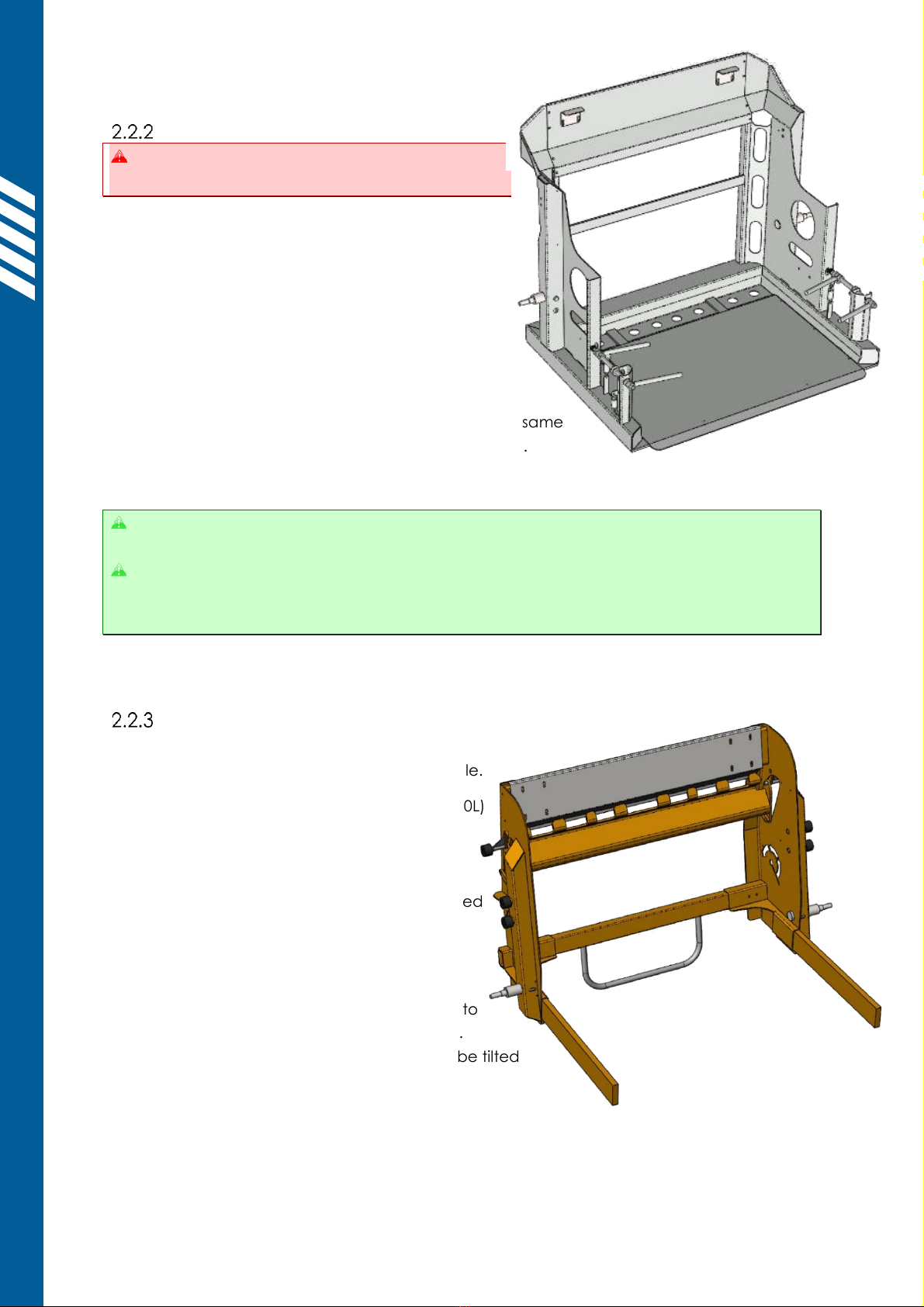
Type-S and Type-E Cradles
Type-S and Type-E cradles should be adjusted
before first use, as set out in §4.3.1.
2.2.2.1 Emplacing bins
Open the door and place the bin onto the cradle:
-Large four-wheeled bins (660L/770L/1100L)
should be positioned central and firm
against the cradle backplate.
-Small two-wheeled bins (80L/120L/240L/360L)
should be positioned to one side of the cradle,
with a wheel inserted into the marked wheel
catch. Two smaller bins can be emptied at the same
time by placing one on each side of the cradle.
Once the bin is correctly emplaced, close the door.
The wheel catches are designed to work with standard EN840 wheelie bins from leading
brands such as Europlast, Sulo, ESE, Weber, Craemer, OnePlastics and Trident.
Some smaller bin manufacturers use tyres which are too wide to fit inside the wheel
catches. Should this issue occur, simply insert additional packers (flat washers) onto the
wheel catch mounting bolts, to increase the spacing as needed.
2.2.2.2 Removing bins
Open the door and, using the grab-handles provided, remove the bin from the cradle.
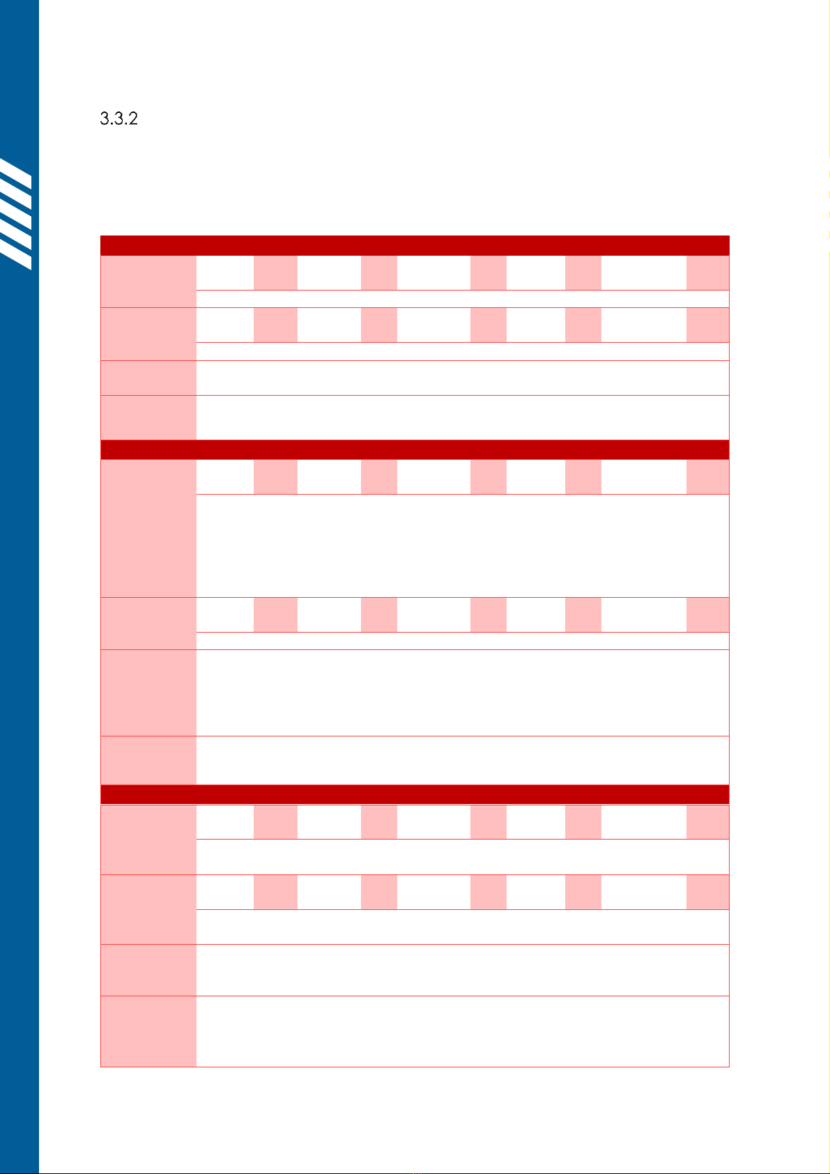
Type-C Cradle
2.2.3.1 Emplacing bins
Open the door and place the bin into the cradle.
-Large four-wheeled bins (660L/990L/1100L)
should be positioned central and firm
against the cradle backplate.
-Small two-wheeled bins
(80L/120L/240L/360L) should be positioned
against one side of the cradle. Two
smaller bins can be emptied
simultaneously, one on either side.
Ensure that the lifting teeth will securely hook into
the bin combing when the cradle begins to lift.
Smaller bins such as 60L and 80L may need to be tilted
Once the bin is correctly emplaced, close the door.

User Manual // Simpro MegaDumper®
Original Instructions // English // v86.0 // February 2022 // Page 12
2.2.3.2 Removing bins
Open the door and, using the grab-handles provided, remove the bin from the cradle. Some
bins may need to be lifted or tilted slightly to disengage the combing from the lifting teeth.
Type-M and Type-N Cradles
2.2.4.1 Emplacing bins
Open the door and place the bin onto the cradle,
central and firm against the cradle backplate.
If using a forklift or powered pallet truck to load the
bin, reduce speed to avoid heavy impacts which
might damage the cradle.
Once the bin is correctly emplaced, close the door.
Most common 610L bulk bins have a
1000x1200mm oblong plan view. These bins
must be loaded in the correct orientation,
with the longer 1200mm faces at front and
rear, and the 1000mm faces at the sides.
Bulk bins are held in place when inverted by
catches These catches
should be positioned to hold the top edges of the bin,
with a maximum free travel of 25mm (1 inch). The
catches can be unbolted and repositioned to allow emptying bins of different sizes.
It is recommended to use a forklift or powered pallet truck when moving bulk bins.
2.2.4.2 Removing bins
Open the door and remove the bin from the cradle.
Type-X (Custom) Cradle
The exact procedure for emplacing bins into a custom
cradle may vary. Contact your Simpro agent for advice or
training if required.
2.2.5.1 Emplacing bins
Open the door and place the bin, drum, or container onto
the cradle, positioned centrally against the backplate.
If using a forklift or powered pallet truck to load the
bin, reduce speed to avoid heavy impacts which
might damage the cradle.
Once the bin is correctly emplaced, close the door.
2.2.5.2 Removing bins
Open the door and remove the bin, drum, or
container from the cradle.

2.3 Operating the controls
The MegaDumper controls are designed to allow safe, intuitive operation of the machine.
Control Panel identification
The MegaDumper may be fitted with a variety of different controls, depending on the
operational and safety requirements of the machine. Use the following table to identify the
correct instructions for your machine.
It is important to understand how to use the controls correctly, as improper operation
may result in a safety hazard or damage to the machine.
The control panel is normally atop the powerpack cover, but on some models, it is
mounted onto a separate enclosure.
Control
Panel Type
Primary Usage
Controls
Image
Refer
Standard
Standard
machines
-RAISE/LOWER
-KEY SWITCH
-VOLTMETER (battery
machines only)
§2.3.2
Autocycle
Machines with an
autocycle
controller
-RAISE/LOWER
-EMERGENCY STOP
-CONTROL MODE
(AUTO/MANUAL)
§2.3.3
VSD
Machines with a
Variable Speed
Drive controller
-JOYSTICK FOR
RAISE/LOWER
-KEY SWITCH
§2.3.4
Safety-
Monitored
Machines with
safety-monitoring
systems to comply
with 13849-1:2015
and AS/NZS4024
up to CAT3/CAT4
-RAISE/LOWER
-EMERGENCY STOP
-CONTROL MODE
(AUTO/MANUAL)
-SAFETY RESET
-Panel describing
the architecture of
the safety-
monitoring systems
(CAT3/CAT4)
Example Only
§2.3.5

User Manual // Simpro MegaDumper®
Original Instructions // English // v86.0 // February 2022 // Page 14
Standard Control Panel
How to operate the controls of a standard
machine, with no PLC or autocycle controller.
1. Before operation, check that the machine is
stable and safe to use as per §2.1.
2. Open the door and place the full bin onto the cradle,
taking care that it is properly positioned as per §2.2, then shut the door.
3. Press and hold the RAISE button until the bin reaches the inverted position, then
release. Wait for the contents of the bin to empty.
Release the RAISE/LOWER button to stop the cradle at any time.
Do not continue pressing the RAISE button after the cradle has reached the top of the
cycle, as this can overheat the hydraulic fluid and cause premature wear on the motor.
4. Press and hold the LOWER button until the cradle rests on the ground.
5. Open the door and remove the empty bin as per §2.2.
6. Repeat from step 1) as required.
Autocycle Control Panel
How to operate the controls of a machine with
an autocycle controller, allowing bins to be
emptied without continuous input.
MegaDumper models that are fitted with an
autocycle control system may be used in either MANUAL or
AUTO mode, selected using a switch on the control panel.
The operating procedure for each mode is as follows:
2.3.3.1 AUTO mode
1. Before operation, check that the machine is stable and safe to use as per §2.1.
2. Open the door and place the full bin onto the cradle, taking care that it is properly
positioned as per §2.2, then shut the door.
3. Turn the mode-selector switch to AUTO.
4. Press the RAISE button once. The cradle will automatically lift, hold the bin inverted for
a short time, and return to ground level.
Press the EMERGENCY STOP button to stop the cradle at any time.
5. Open the door and remove the empty bin as per §2.2.
6. Repeat from step 1) as required.
2.3.3.2 MANUAL mode
1. Before operation, check that the machine is stable and safe to use as per §2.1.
2. Open the door and place the full bin onto the cradle, taking care that it is properly
positioned as per §2.2, then shut the door.
3. Turn the mode-selector switch to MANUAL.

4. Press and hold the RAISE button until the bin reaches the inverted position, then
release. Wait for the contents of the bin to empty.
Release the RAISE/LOWER button or press the EMERGENCY STOP button to stop the cradle
at any time.
5. Press and hold the LOWER button until the cradle returns to the ground.
6. Open the door and remove the empty bin as per §2.2.
7. Repeat from step 1) as required.
VSD Control Panel
How to operate the controls of a VSD machine,
with a joystick to allow progressive control of
the lifting speed.
1. Before operation, check that the machine is
stable and safe to use as per §2.1.
2. Open the door and place the full bin onto the cradle, taking care that it is properly
positioned as per §2.2, then shut the door.
3. Push the JOYSTICK FULLY FORWARD to begin lifting the bin.
4. When the bin reaches the top of the mast and starts to invert, gently move the
JOYSTICK SLIGHTLY BACK so that the material is poured from the bin in a controlled
manner, as desired. Wait for the contents of the bin to empty.
Release the JOYSTICK to stop the cradle at any time.
5. Pull the JOYSTICK FULLY BACK until the cradle rests on the ground.
6. Open the door and remove the empty bin as per §2.2.
7. Repeat from step 1) as required.
Safety-Monitored Control Panel
How to operate a machine with a safety-
rated PLC control unit and CAT3/CAT4
monitoring system.
MegaDumper models that are fitted with a
safety-monitored control system may be used in
either MANUAL or AUTO mode, selected using a
switch on the control panel.
The operating procedure for each mode is as follows:
2.3.5.1 AUTO mode
1. Before operation, check that the machine is stable and safe to use as per §2.1.
2. Open the door. If the door is locked, press the LOWER button to unlock it.
3. Place the full bin onto the cradle, taking care that it is properly positioned as per §2.2,
then shut the door.
4. Turn the mode-selector switch to AUTO.
5. Press and hold the blue RESET button for two seconds.

User Manual // Simpro MegaDumper®
Original Instructions // English // v86.0 // February 2022 // Page 16
a. The safety system will now conduct an auto-diagnostic check. If no faults are
detected, the blue light will go out and the machine will be enabled.
a. If the safety system detects a fault, the blue light will not go out and the
machine will be disabled. The fault must be found and corrected before the
machine can be used, as per §4.10.
6. Press the RAISE button once. The cradle will automatically lift, hold the bin inverted for
a short time, then return to ground level.
Press the EMERGENCY STOP button to stop the cradle at any time.
7. Open the door and remove the empty bin as per §2.2.
8. Repeat from step 1) as required.
Once the cradle has lowered, the door is automatically unlocked for about 15 seconds. If
the door re-locks, press the LOWER button to unlock it at any time.
2.3.5.2 MANUAL mode
1. Before operation, check that the machine is stable and safe to use as per §2.1.
2. Open the door. If the door is locked, press the LOWER button to unlock it.
3. Place the full bin onto the cradle, taking care that it is properly positioned as per §2.2,
then shut the door.
4. Turn the mode-selector switch to MANUAL.
5. Press and hold the blue RESET button for two seconds.
a. The safety system will now conduct an auto-diagnostic check. If no faults are
detected, the blue light will go out and the machine will be enabled.
b. If the safety system detects a fault, the blue light will not go out and the
machine will be disabled. The fault must be found and corrected before the
machine can be used, as per §4.10.
6. Press and hold the RAISE button until the bin reaches the inverted position, then
release. Wait for the contents of the bin to empty.
Release the RAISE/LOWER button or press the EMERGENCY STOP button to stop the cradle
at any time.
7. Press and hold the LOWER button until the cradle rests on the ground.
8. Open the door and remove the empty bin as per §2.2.
9. Repeat from step 1) as required.
Once the cradle has lowered, the door is automatically unlocked for about 15 seconds. If
the door re-locks, press the LOWER button to unlock it at any time.

3.Safety Information
The MegaDumper has been designed to be as safe as possible without restricting the ease-
of-use and versatility of the machine.
Before the MegaDumper is used for the first time, a Hazard and Risk Assessment should be
completed as per §3.3.
3.1 Safety features
Safety features of the standard MegaDumper design include:
1. Mesh and sheet-metal panels which prevent access to all moving parts.
2. A safety interlock system which disables the machine unless the door is shut, and
electrically locks the door as soon as the cradle leaves the ground.
3. A tipping action which maintains the weight of the bin within the machine footprint.
4. A pressure-compensating lowering valve which automatically regulates the lowering
speed regardless of the weight of the bin.
5. A control system which either:
a. stops the machine unless continuous operator input is received, or;
b. features a prominent EMERGENCY STOP button to disable the machine.
3.2 Reasonably foreseeable misuse
Reasonably foreseeable misuse considered in the standard MegaDumper design includes:
1. Attempts to use the machine by untrained operators;
2. Attempts to empty bins that the cradle is not specifically designed to hold;
3. Attempts to bypass the door interlock or other safety systems;
4. Attempts to clear spilt material from inside the guarding without proper procedures;
5. Attempts to clean the machine without following proper procedures.
3.3 ISO12100 Hazard and Risk Assessment Guide
As set out in §3.4, organisations seeking to demonstrate ISO13849 conformance must assess
the safety of their machinery in the intended conditions of use, considering all relevant
factors such as the area the machine is to be used, the training of operators, the proximity of
other persons, frequency of use, etc.
The following section uses the ISO12100:2010 risk assessment model to assist prospective
MegaDumper owners in carrying out this process. Hazards intrinsic to the MegaDumper are
pre-filled, while blank spaces are provided to assess application-specific hazards.
Risk assessment and risk reductionard issued by the
International Standards Organisation. It describes procedures for identifying hazards and
estimating and evaluating risks during relevant phases of a machine life cycle.

User Manual // Simpro MegaDumper®
Original Instructions // English // v86.0 // February 2022 // Page 18
As with all powered industrial equipment, some hazards will remain despite any
precautions undertaken by the manufacturer or owner of the machine. It is essential that
operators are aware of these residual hazards and what they must do to prevent harm to
themselves or to others, as set out in §3.3.3.
The ISO12100 risk assessment model
In the ISO12100 risk assessment model, each identified hazard is given a Risk Factor, from
which is derived a Risk Evaluation. These parameters are assessed as follows.
3.3.1.1 Determining the Risk Factor
The Risk Factor associated with any given hazard may be calculated from the following
table, using the formula: Risk Factor = LO x FE x DPH x NP
3.3.1.2 Determining the Risk Evaluation
Once the Risk Factor has been calculated, the Risk Evaluation of the hazard can be
determined from the following table:
Risks evaluated as Very High, Extreme or Unacceptable are likely to require additional or
uprated safety functions, as set out in §3.4. These must be specified at the time of order.
LO
Likelihood of
Occurrence
FE
Frequency
of Exposure
DPH
Degree of
Possible Harm
NP
Number of
Persons at risk
0.1
Impossible, or
possible only in
extreme
circumstances
0.1
Infrequently
0.1
Scratch or
bruise
1
1 2 persons
0.5
Highly unlikely
though
conceivable
0.2
Annually
0.5
Laceration,
mild ill-health
2
3 7 persons
1
Unlikely but
could occur
1
Monthly
1
Break minor
bone or illness
(temporary)
4
8 15 persons
2
Possible but
unusual
1.5
Weekly
2
Break major
bone or illness
(permanent)
8
16 50
persons
5
Even chance
could happen
2.5
Daily
4
Loss of 1 limb or
eye/serious
illness
(temporary)
12
51 or more
persons
8
Probable not
surprised
4
Hourly
8
Loss of 2 limbs
or eyes/serious
illness
(permanent)
-
-
10
Likely, only to be
expected
5
Constantly
15
Fatality
-
-
15
Certain, no
doubt
-
-
-
-
-
-
Risk Factor
0-1
2-5
6-10
11-50
51-100
101-500
501-1000
1001 +
Evaluation
Negligible
Very
Low
Low
Significant
High
Very
High
Extreme
Unaccept
able
Identified Hazards
The following hazards have been identified that are intrinsic to the MegaDumper design. For
each hazard a full Risk Evaluation has been completed and control measures described.
Blank template spaces are also provided to identify, assess, and describe control measures
for application-specific hazards.
Entanglement or amputation of fingers or limbs in moving parts
Operator
LO:
0.5
FE:
4
DPH:
1
NP:
1
Risk
Factor:
2
Guarding prevents access to all moving parts and trapping hazards.
Other
persons
LO:
1
FE:
4
DPH:
1
NP:
1
Risk
Factor:
4
As above.
Control
measures
Operators are responsible to obey warning signs fitted to the machine and
instructions, regarding keeping himself and others clear of all moving parts.
Comments
The MegaDumper is designed so that trapping hazards are eliminated,
minimized or isolated.
Crushing by unauthorized rapid descent of cradle
Operator
LO:
0.5
FE:
4
DPH:
1
NP:
1
Risk
Factor:
2
The operator is protected from the cradle by the frame and guarding during
operation. A door safety interlock ensures that the door can only be opened
when the cradle is on the ground, and the cradle cannot be raised unless
the door is closed and locked.
Significant safety margins ensure that the probability of failure of any steel,
hydraulic, or control parts failing is very low.
Other
persons
LO:
0.5
FE:
4
DPH:
1
NP:
1
Risk
Factor:
2
As above.
Control
measures
Operators are responsible to obey all instructions and warning signs,
regarding keeping personnel away from the area beneath the cradle when
raised.
The machine must be regularly maintained, and all faults repaired
immediately.
Comments
A hydraulic speed-control valve limits the maximum speed of descent in
normal use.
Operator or others being hit by falling or flying debris
Operator
LO:
1
FE:
4
DPH:
0.5
NP:
1
Risk
Factor:
2
The operator is protected from the cradle by the frame and guarding during
operation. There is some risk if items such as broken glass are being tipped.
Other
persons
LO:
1
FE:
4
DPH:
0.5
NP:
1
Risk
Factor:
2
There is some risk to others standing close to the bin if items such as broken
glass are being tipped
Control
measures
Operators are responsible to obey all instructions and warning signs
regarding keeping personnel from the machine while in use.
If tipping product such as glass, metal or liquids, suitable PPE should be worn.
Comments
Other manuals for MegaDumper
2
Table of contents
Other Simpro Industrial Equipment manuals


