Hofmann geodyna 6300 User manual

Calibration instructions geodyna 6300
Page 1 of 8
Date 2 Oct 2001
Basic settings of diameter and distance potentiometers with code
C80
Service and test functions become accessible by simultaneously
pressing and holding the C and the balancing mode keys and by
rotating the main shaft.
… is read out for 1 second.
The display proceeds automatically to the basic settings.
Then the basic settings of .15 to .2 Volt of the diameter and distance
potentiometers are read out.
The left-hand reading refers to the basic setting of the diameter potentiometer.
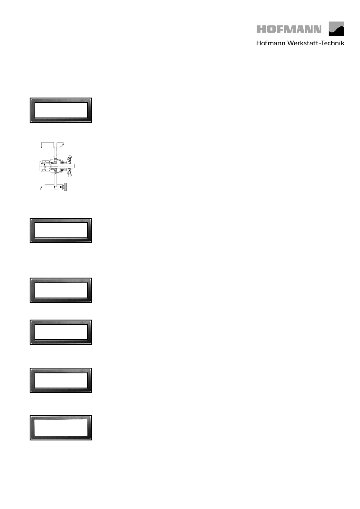
Engage the calibration tip of the gauge head with the calibration groove in the
board of the vibratory system. If the slider voltage of the diameter potentiometer
is not within a range of .15 to .20 Volt, turn the potentiometer shaft to bring the
voltage to within this range.
The right-hand reading refers to the basic setting of the distance potentiometer.
If the gauge arm is in left home position and if the slider voltage of the distance
potentiometer is not within a range of .15 to .20 Volt, turn the potentiometer
shaft to bring the voltage to within this range.
Return the gauge arm into the left home position and press the C key to store
the values.
The following reading appears:
Fully pull out the gauge arm, hold, and press the C key to store the value.
The following reading appears:
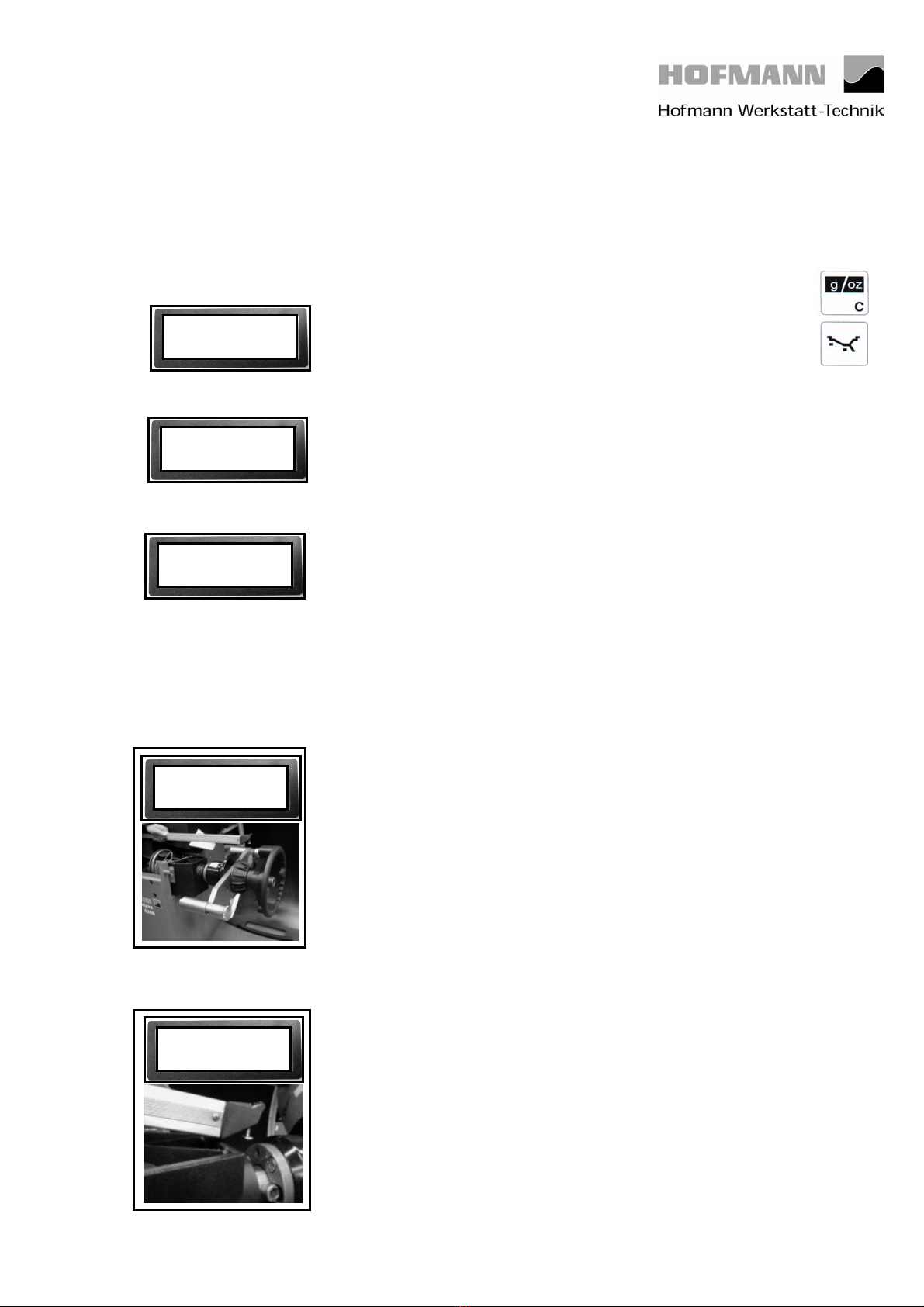
Engage the calibration tip on the bottom of the gauge head with the calibration
groove in the board of the vibratory system and press the C key to store the
value.
C80.
1.
0,17 0,16
2 0,16
3 0,16

Calibration instructions geodyna 6300
Page 2 of 8
Date 2 Oct 2001
The following reading appears:
Raise the gauge arm, apply the calibration tip of the diameter calibration rod
into the calibration groove of the board of the vibratory system and the
calibration tip of the gauge arm into the recess at the lower end of the
calibration rod. Pull out the gauge arm until the calibration rod is in vertical
position.
Press the C key to store the value.
The following reading appears:
Step no. 5 has no function yet.
The following reading appears:
Raise the gauge arm and pull out at least 3 times slowly until it clamps. After
each clamping hold the gauge arm for at least 1 second in the instantaneous
clamping position before repeating this procedure. When the gauge arm had
been pulled out and clamped 3 times, the reading proceeds automatically with
step no. 7.
The following reading appears:
Pull out the gauge arm at least 7 times with increased constant speed until it
clamps. After each clamping hold the gauge arm for at least 1 second in the
instantaneous clamping position before repeating this procedure. When the
gauge arm had been pulled out and clamped 7 times, the reading proceeds
automatically with C- -.
The following reading appears:
Calibration is completed and must be stored by entering C90.
4. 0,16
5.
6.
7.
C - -

Calibration instructions geodyna 6300
Page 3 of 8
Date 2 Oct 2001
Measuring adaptor flange and zero plane using code C81.
Service and test functions become accessible by simultaneously pressing and
holding the C and the balancing mode keys and by rotating the main shaft.
The following reading appears:
Apply the gauge arm on the contact surface of the test rotor and press the C
key to store the value.
The following reading appears:
Calibration is completed and must be stored by entering C90.
C 81.
C - -
1. 0

Calibration instructions geodyna 6300
Page 4 of 8
Date 2 Oct 2001
3 D SAPE Calibration of width gauge arm with code C82
Service and test functions become accessible by
simultaneously pressing and holding the C and the balancing
mode keys and by rotating the main shaft.
If the width gauge arm is in right home position and if the slider voltage of the
width potentiometer is not within a range of 4.25 to 4.30 Volt, turn the
potentiometer shaft to bring the voltage to within this range. Press the C key to
store the value.
The following reading appears:
Apply the gauge head of the width gauge to the outer surface of the adaptor
flange and press the C key to store the value.
The following reading appears:
Insert the calibration weight supplied with the machine into the adaptor flange
so that it protrudes to the right.
Apply the width gauge arm to the outer surface of the calibration weight and
press the C key to store the value.
The following reading appears:
Calibration is completed and must be stored by entering C90.
C82
1 4.26
2 0,77
3 2,33
C - -

Calibration instructions geodyna 6300
Page 5 of 8
Date 2 Oct 2001
Code C83 – Calibration of unbalance measurement
Clamp the test rotor, enter distance, 15“ diameter and 6.5“ width.
Service and test functions become accessible by simultaneously pressing and
holding the C and the balancing mode keys and by rotating the main shaft.
So press and hold the keys and rotate the main shaft until code C83 is read out.
The calibration function is enabled as soon as the C and balancing mode keys
are released.
Then the following reading appears:
Press the START key to start a measuring run.
After the measuring run the following reading appears:
2 = step no. 2 100 = suggested calibration weight in grams
If necessary, press and hold the precision key and rotate the main shaft to set
the actual weight.
Insert a calibration weight of 100 gms in the left-hand plane of the test rotor and
press the C key to acknowledge this weight. Then proceed to the next step.
The following reading appears:
Press the START key to start a measuring run.
1 Start
2 100
3 Start 100

Calibration instructions geodyna 6300
Page 6 of 8
Date 2 Oct 2001
After the measuring run the following reading appears:
Remove the 100 gm calibration weight from the left-hand plane of the test rotor
and insert it into the right-hand plane of the test rotor. Then press the START
key.
After the measuring run the following reading appears:
Press the C key.
The following reading appears:
The ambient transducer temperature is read out for 1 second.
After temperature measurement the following reading appears:
Remove the 100 gm calibration weight from the test rotor. Press the START key
in order to proceed with instantaneous electrical compensation of residual
adaptor unbalance.
After the measuring run the following reading appears:
Insert the calibration weight supplied with the machine at the left inner side of
the adaptor flange. Press the START key.
The following reading appears:
Calibration is completed and must be stored by entering C90.
4 Start 100
5
6 21 Temp.
7
8 Start
C - -

Calibration instructions geodyna 6300
Page 7 of 8
Date 2 Oct 2001
Calibration of residual unbalance of main shaft
and drive pulley using code C84
Service and test functions become accessible by simultaneously pressing and
holding the C and the balancing mode keys and by rotating the main shaft.
The following reading appears for one second:
Then the following reading appears:
Press the START key to start a measuring run.
Then the following reading appears:
Calibration is completed and must be stored by entering C90.
C84.
C84. Start
C - -

Calibration instructions geodyna 6300
Page 8 of 8
Date 2 Oct 2001
Storing calibration data with code C90
Service and test functions become accessible by simultaneously pressing and
holding the C and the balancing mode keys and by rotating the main shaft.
The following reading appears:
Press the precision key and rotate
the main shaft to set 1.
The following reading appears:
Press the C key to complete calibration.
The following reading appears:
Press the STOP key to quit the service mode.
C 90. 0
C 90. 1
C - -
Table of contents
Other Hofmann Industrial Equipment manuals