CHINT NWC5 Series Installation instructions
Standard:IEC 60831-1-2014
IEC 60831-2-2014
NO:2021.01
NWC5/NWC6 Series
Self-healing Low Voltage
Shunt Capacitors
Safety Warning
1 Only professional technicians are allowed for installation and maintenance.
2 Installation in any damp, condensed-phase environment with inflammable and explosive gas is
forbidden.
3 When the product is being installed or maintained, the power must be switched off.
4 You are prohibited from touching the conductive part when the product is operating.
Type Key and Definitions
Conditions for Normal Use, Installation and
Transportation, and Storage
Key Technical Parameters and Performance
Installation, Commissioning and Operation
Main Features, Outline and Installation Dimensions
Analysis and Troubleshooting of Faults
Maintenance and Storage
Product Selection and Ordering Information
11 Environmental Protection
01
01
01
02
04
04
06
06
07
08
08
Use Purpose and Application Range
Warranty Period, Environmental Protection and Law & Regulations
Model
Harmonic source power
/transformer capacity
Harmonic source power
/transformer capacity
Harmonic source power
/transformer capacity
NLL≤10%NLL≤20%20%≤NLL≤40%
Voltage total
harmonic distortion THDu≤3%3%<THDu≤5%THDu>5%
Rated voltage
of capacitor 0.4kV, 0.45kV 0.45kV, 0.48kV 0.48kV, 0.525 kV
Harmonic
suppression measures
Not needed Recommend to use
series reactor 7%
Series reactor 7%
or 14%
Conditions for Normal Use, Installation and Transportation, and Storage
3.3.3. If detuning low voltage series reactor is installed at the front end of the capacitor, the rated voltage of
the capacitor should be selected as below: If the reactance rate of the reactor is 6% or 7%, the rated voltage
of the capacitor should be 0.45kV or 0.48kV, if the reactance rate of the reactor is 12% or 14%, the rated
voltage of the capacitor should be 0.525kV.
Table 1 Capacitor selection and harmonic suppression measures under harmonic environment
Note: If harmonic power ratio NLL>40%, user must install CKSG series reactor or take harmonic suppression measures.
01
3.1 Environmental conditions: See Table 2 for ambient air temperature, relative temperature and altitude.
3.2 Installation conditions: On condition that the safety precautions are met, the installation site should be
free from hazardous gases and vapors, conductive or explosive dusts, and strong mechanical vibration.
3.3 Application conditions
3.3.1 The rated voltage of the capacitor must be higher than the voltage of user’s grid. When the
environmental conditions exceed the limits in 3.1, user must derate the capacitor by raising its rated voltage,
otherwise the service life of the capacitor can be significantly shortened after long-term overvoltage or
overtemperature operation.
3.3.2 Harmonic current amplification is the primary cause for capacitor damage. Common harmonic sources
include: power electronic equipment, frequency converter (energy saving transformation, such as motor
speed regulation, variable frequency air conditioner, etc.), DC rectifier, inverter, electrolytic plating
equipment, electric arc furnace and intermediate frequency furnace, etc. See Table 1 for capacitor selection
and harmonic suppression measures under harmonic environment:
Type Key and Definitions
NWC5/NWC6 Series Self-healing Low Voltage Shunt Capacitors
Use Purpose and Application Range
NWC5/NWC6 series self-healing low voltage shunt capacitors (hereinafter referred to as
capacitors) are applicable to power frequency AC power systems with rated voltage up to 1,000V
for power factor increase, reactive power loss reduction and voltage quality improvement.
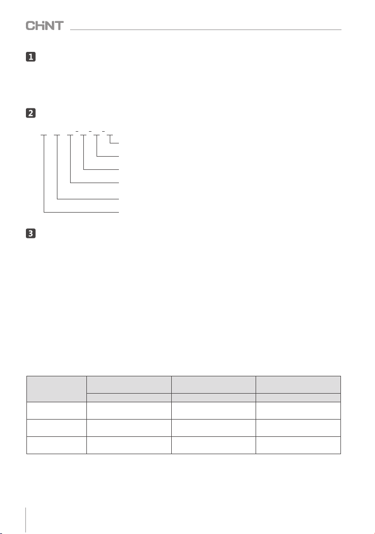
Phase number: 3-three phase, 1-single phase,3T-three phase insert type
Rated capacity (kvar)
Rated voltage (kV)
Design serial number: 5-refers to single layer stretched aluminum enclosure
6- refers to dry type capacitor
Self-healing low voltage shunt capacitor
Group company code
N WC □ □ □ □
3.3.4 See 7.2 for product installation spacing. We suggest double the installation spacing if the product is
installed above an altitude of 2000 meters. User should take effective measures to ensure good ventilation
and heat dissipation of the capacitors under high temperature environment and keep the capacitors away
from heat source.
3.4 Transportation conditions: The capacitors should be transported within original package (packed in foam
box). The product should be handled carefully during transportation, to prevent the capacitor body from
deformation due to collision. The product should be placed on upper level when loaded onto the truck. The
capacitor assembly must be placed vertically during transportation, with an inclination less than 30 degrees.
Key Technical Parameters and Performance
02
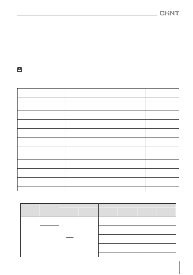
4.1 See Table 2 for key technical parameters
Table 2 Key technical parameters
4.2 See Table 3 for specifications and outline dimensions of main models
Table 3 Specifications and outline dimensions of main models
NWC5/NWC6 Series Self-healing Low Voltage Shunt Capacitors
0.4~0.525
1~50
Fixing bolt torque (N·m)M12 bolt≤10, M16 bolt≤12
Rate voltage (kV)See Table 3
Rate capacity (kvar)See Table 3
Rate frequency (Hz)50 or 60 Default 50
Capacitance deviation (%) -5~+8 Short circuit
discharge before test
Dissipation factor ≤ 30kvar product: tanδ≤0.0012
>30kvar product: tanδ≤0.0015
Withstand voltage (kV)Inter-pole: power frequency 2.15UN, 2s
Pole-to-case: 2.0 UN+2 kV or 3 kV (take higher), 5s
Maximum allowable
over voltage
1.1UN, no more than 8h of continuous operation
within 24h
Maximum allowable
overcurrent
1.3IN, no more than 2h of continuous operation
within 24h Short time≤2.0IN
Self-discharge
characteristics
Residual voltage drops from √2UN to 75V(DC)
or below within 3min after power off.
Ambient temperature (℃) -25~+50 (-25/C)
Customizable -40~+50
Relative temperature ≤50% at 40℃, ≤90% at 20℃
Altitude (m)≤2000
Tightening torque (N·m)M6 screw ≤7, M8 screw ≤10
Safety protection Self-healing + overpressure protection+
discharge device
Short circuit
discharge before test
Installation method Vertical
Rated
voltage
UN(kV)
Optimal
capacity
Qc(kvar)
Rated current IN(A)Outline and installation dimensions
3-three
phase
1-single
phase
Capacity
range
Outline
dimensions
Installation
dimensions
Figure
number
0.23
1(T)1Φ60×175 M10×10 Figure 1
2, 3, 4(T)2~4Φ60×240 M10×10 Figure 1
5, 7.5, 8,
10, 15, 16,
18, 20, 25,
30
5~6Φ76×240 M10×10 Figure 2
7.5~8Φ76×290 M10×10 Figure 2
10~12 Φ86×290 M12×16 Figure 2
14~15 Φ96×290 M16×25 Figure 2
16~18 Φ106×290 M16×25 Figure 3
20~22 Φ116×290 M16×25 Figure 3
24~30 Φ136×290 M16×25 Figure 3
Qc
√3UN
Qc
UN

Protective
characteristics Name and function of support devices Typical models
Transient
overvoltage
protection
Zinc-oxide surge arrestor or surge protector FYS-0.28 or NU6-2
Transient
overcurrent
protection
Capacitor dedicated contactor, current limiting reactor,
or smart compound switch with zero-cross detection. CJ19, XD1 or ZCK
Steady stage
over voltage
protection
Generally, compensation controller can provide
over voltage protection.NWK1-G, NWKL1
Steady stage
overcurrent
protection
Thermal relay or capacitor switch with overcurrent
protection function.JR36 or ZCK
Short circuit
protection
Choose fast acting fuse for short circuit protection. For
capacitors with capacity<30kvar, user can use miniature
circuit breaker for short circuit protection. For capacitors
with capacity ≥30kvar, miniature circuit breaker is not
recommended.
RT36 or NT00
0.25
1, 2(T)1~2Φ60×175 M10×10 Figure 1
2, 3, 4(T)3~4Φ60×240 M10×10 Figure 1
5, 7.5, 8,
10, 15, 16,
18, 20, 25,
30
5~8Φ76×240 M10×10 Figure 2
10 Φ76×290 M10×10 Figure 2
12~14 Φ86×290 M12×16 Figure 2
15~18 Φ96×290 M16×25 Figure 2
20~22 Φ106×290 M16×25 Figure 3
24~26 Φ116×290 M16×25 Figure 3
28~30 Φ136×290 M16×25 Figure 3
0.4, 0.45
1, 2(T)1~2Φ60×110 M10×10 Figure 1
3, 4, 5(T)3~5Φ60×175 M10×10 Figure 1
6, 7.5, 8(T)6~8Φ60×240 M10×10 Figure 1
0.4, 0.415,
0.45
5, 7.5, 8,
10, 15, 16,
18, 20, 25,
30, 40
5~8Φ76×180 M12×16 Figure 2
10~12 Φ76×240 M12×16 Figure 2
14~16 Φ76×290 M12×16 Figure 2
18~20 Φ86×290 M12×16 Figure 2
22~25 Φ96×290 M16×25 Figure 2
26~30 Φ106×290 M16×25 Figure 3
32~40 Φ116×290 M16×25 Figure 3
Note: The dimensions of 0.525 kV, 0.69kV products may be different from those in the table, please refer
to the real products. The wiring terminals of models with suffix “T” are of insert type, among which the
outline dimension of 0.525 kV(1~8)Tkvar products areΦ60×240 (see Figure 1). See Figure 4 for outline
dimensions of split-phase compensation products with YN. See 5.0 for figure numbers corresponding to
the outline and installation dimensions in the table.
Qc
√3UN
Qc
√3UN
Qc
√3UN
Qc
UN
Qc
UN
Qc
UN
03
Table 3 (continue)
4.3 The capacitors are placed in the capacitor compensation cabinet which should provide the following
protection measures. See Table 4 for details.
Table 4 Capacitor protection measures in cabinet
NWC5/NWC6 Series Self-healing Low Voltage Shunt Capacitors
Note: Other capacitors with special voltage and star connection YN split-phase compensation is customizable,
for example: NWC5-0.45-15-3YN.
04
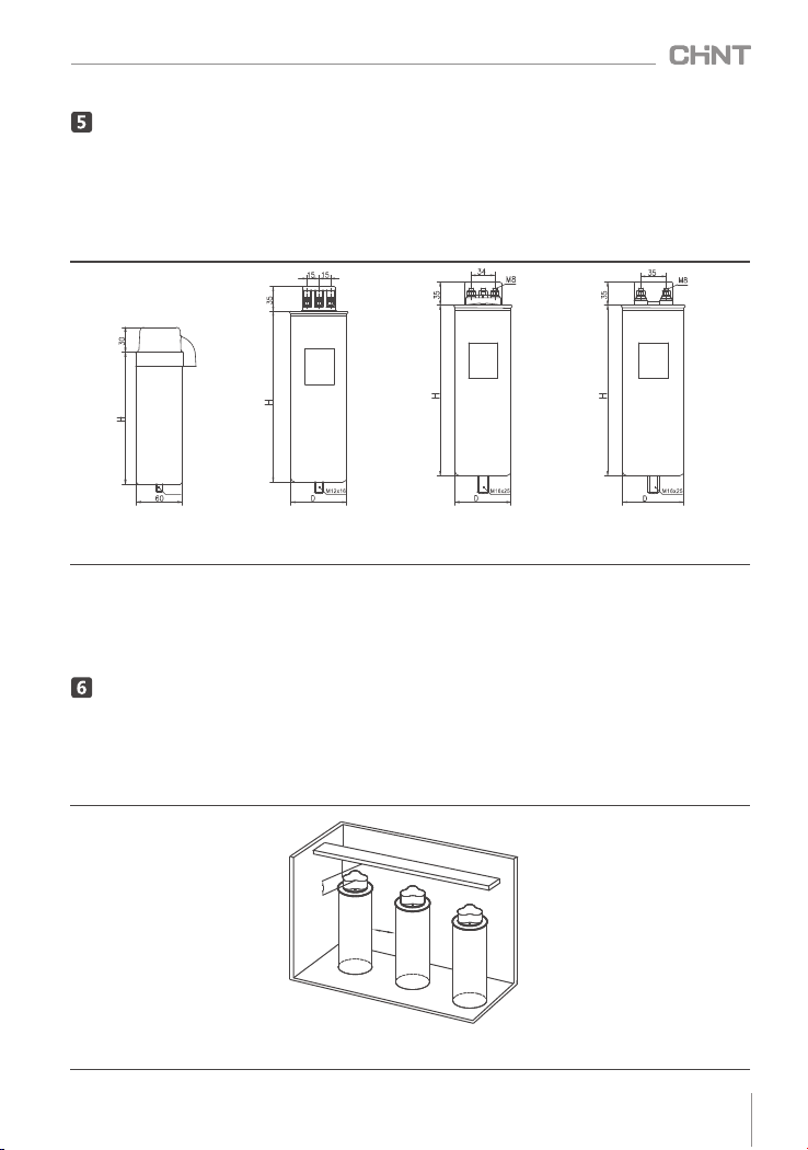
Main Features, Outline and Installation Dimensions
Installation, Commissioning and Operation
NWC5/NWC6 Series Self-healing Low Voltage Shunt Capacitors
NWC5/NWC6 series products use cylindrical stretched aluminum enclosure, with pressure isolation
protection and self-discharging functions. NWC5 series products are oil immersed capacitors. NWC6 series
products are dry type capacitors which use fire retardant environmental protection material as packing
medium. These products are all designed with compact structure, light weight and are easy for installation
and maintenance. See Figure 1-4 below for outline and installation dimensions.
Figure 1
Insert type product
Figure 2
Cage type product
Figure 3 Conducting
rod type 3-phase
compensation product
Figure 4 Conducting
rod type split-phase
compensation product
Note: Refer to Table 3 based on capacitor model, then look for the outline and installation dimensions in Figure 1
~Figure 4.
Example: For model NWC5-0.45-20-3, user can refer to Table 2 and find that the outline dimension is
Φ86×290 and the installation dimension is M12×16.
6.1 Installation and Fixing
The bottom mounting screws are included in the package. User just need to tighten the screws with
proper torque when installing the products.
6.2 Installation spacing
Figure 5 Capacitor installation drawing
M1 0x1 0
S2
S1

05
NWC5/NWC6 Series Self-healing Low Voltage Shunt Capacitors
Table 5 Installation spacing and safety distance
Capacity (kvar)Minimum installation
spacing S1(mm)
Safety distance at the top
of capacitors S2(mm)
1~20 ≥50
22~32 ≥50
35~60 ≥50
20
30
40
6.3 Wiring requirements
The capacitors should be connected by stranded soft conductors, with pressed dedicate copper
connecting lug. See Table 6 for the selection of conductor sectional area.
Table 6 Selection of conductor sectional area
Rated voltage (kV)Rated capacity (kvar)2
Conductor sectional area (mm )
0.4, 0.45, 0.525 ≤10 4.0
0.4, 0.45, 0.525 12~20 6.0
0.4, 0.45, 0.525 24~32 10.0
0.4, 0.45, 0.525 35~60 16.0 or 25.0
6.4 Preparation and inspection before use
6.4.1 Before using the capacitor, user should check if the model on the nameplate is consistent with that of
the product. User should also check if the included accessories are complete;
6.4.2 Capacitor testing: Use digital capacitance meter to test the capacitance value between any of the two
phases of the 3-phase capacitor, the result should be about half of the rated value;
6.4.2 Before using the capacitor, user should check if all the connections are secure and if the dust guard is
installed, make sure the capacitor is reliably grounded.
6.5 Monitoring and recording during operation
6.5.1 User should check the operating status of the capacitors on a regular basis, check if the 3-phase current
is balanced by using the amperemeter in the cabinet.
6.5.2 If the 3-phase current is not balanced, use clamp on amperemeter to test the current and voltage of
phase A, phase B and phase C of each group of capacitors.
6.5.3 If there is voltage but no current between phases, it means the overpressure protector is disconnected,
user should maintain the product in time or replace it if necessary.
6.5.4 Check the surface temperature of capacitor case during operation, if the temperature of any individual
capacitor case exceeds 65℃, maintain the product or replace it if necessary; if the temperature of all the
capacitor cases is higher than 65℃, take effective ventilation and heat dissipation measures and check if any
harmonic source device (such as frequency converter, rectifier and inverter, and medium and high frequency
heating furnace) is used at user load end.
6.6 Operation procedure, method and precautions for shut down
6.6.1 If any deformation, oil leakage is found on the capacitor case or the reactive compensation controller
is not working normally, shut down the equipment for inspection and repair.
6.6.2 If the busbar in the cabinet is of bottom-in and top-out type, user must disconnect the bus before
replacing the capacitors or other electric components. However, user only needs to disconnect the isolation
switch in the cabinet when changing the secondary wiring or testing the capacitors.
6.6.3 Before testing and touching the capacitors, user must conduct short circuit discharge between each
two terminals of the 3-phase capacitor.
Maintenance and Storage
7.1 Daily maintenance and calibration
Check if the operating current of the capacitor is normal by using the amperemeter and compensation
controller in the cabinet. Check if there is any deformation, oil leakage and overheating.
Abnormalities such as overcurrent and overtemperature caused by harmonic will reduce the service life

06
Analysis and Troubleshooting of Faults
Table 7 Analysis and Troubleshooting of Faults
NWC5/NWC6 Series Self-healing Low Voltage Shunt Capacitors
of the capacitor and can cause damage to other components and conductors in the cabinet due to overload.
7.2 Maintenance during operation
Tighten the terminal screws of the capacitor on a regular basis (once half a year) to prevent poor
contact. Remove dust and greasy dirt also.
User should pay close attention to the cabinet and replace any damaged capacitor in time if any under
-compensation of power factor occurs due to significant capacitance drop (50% current decrease), otherwise
it may lead to penalty. If all the capacitors are operating and in good condition but the power factor still
cannot meet requirement, user must add capacity in time to ensure the automatic cycle operation of the
capacitors.
7.3 Service cycle
User should determine the service cycle based on the application conditions, the recommended service
cycle for cabinet is once half a year.
7.4 Maintenance for long-term idle
If the capacitor has been idled for one year or longer, please check if its capacitance value is within the
allowable deviation range (-5%~+8%); conduct pole-to-case voltage withstand test again (apply AC 3kV for
5 seconds); or use megameter to test if the insulation resistance between the three phase terminals and the
case is larger than 100MΩ before using the product.
7.5 Storage conditions, storage period and precautions
The smart capacitor should be stored in a dry and well-ventilated room and protected from rain, moist,
chemicals and dust. The maximum storage period of the product is 36 months. Do not put the smart
capacitor or its package directly on the floor.
1
The measured current of a
newly connected capacitor is
much smaller than the rated
current on its nameplate (same
for multiple capacitors).
If a capacitor with higher rated
voltage is connected to 380V grid,
the actual output current will be
much smaller, which is normal.
There is nothing wrong with the
capacitor, it is just derated.
User should determine the
status of a capacitor based
on its measured capacitance
value (μF). The actual
operating current IC=
Uc/UN ×IN
2
The current of the capacitor is
closed to rated current when
it is first put into operation,
but the current drops after a
period of time.
The current drops as the capacitance
value of the capacitance decreases.
There are several reasons for
capacitance decrease such as
improper use, large harmonic or
quality defect.
Find out the reason and
solve the problem. User
must replace the capacitor
if the capacitance value
drops below 50%.
3
The terminal screws of the
capacitor generate heat or
even turn into black during
operation.
The wire nuts are loose or not
tightened properly during installation.
If the nuts are tightened properly, the
reason might be long-term
overcurrent due to harmonic current
amplification in the grid.
Tighten the nuts, replace
nuts, flat gaskets, elastic
washer if necessary.
4
The fuse in branch circuit
blows frequently (or miniature
circuit breaker trips frequently);
the CJ19 contactor fuses; the
current-limiting resistance
burns frequently; the surface
of XD1 current-limiting reactor
These symptoms are typical when
the grid harmonic is too big or
there is intermittent resonance in
the grid.
Conduct grid harmonic test
or check if there are
harmonic sources such as
frequent converter, rectifier,
intermediate frequency
furnace or electric-arc
furnace installed at load
No.Faults Cause analysis Troubleshooting method

07
10.1 User should provide product parameters such as rated voltage, rated capacitance, number of phases,
etc;
10.2 User should provide as many application conditions as possible, such as altitude, grid harmonic
environment and application industry.
Product Selection and Ordering Information
Environmental Protection
In order to protect the environment, the product or product parts should be disposed of according to
the industrial waste treatment process, or be sent to the recycling station for assortment, dismantling and
recycling according to local regulations.
NWC5/NWC6 Series Self-healing Low Voltage Shunt Capacitors
case cracks, etc.end. See 3.3.2 for harmonic
suppression measures.
5
Sometimes there is buzzing
sound in the cabinet during
operation.
There is harmonic current passing
through the capacitor.
User must take harmonic
suppression measures if
the harmonic current is too
big (same as 4)
6
There is significant current
increase when adding a
capacitor into a group.
Either abnormal power frequency
resonance (underloading), or
harmonic current amplification or
there is resonance.
Same as 4
7
Slight deformation occurs to
the capacitor case after the
capacitor has been used for a
period of time, and no current
can be detected.
Long-term overtemperature or
overcurrent operation of the
capacitor which cause self-healing
breakdown of internal components
that generates gases and increases
internal pressure. When the
overpressure protector breaks, slight
deformation can occur to the
capacitor case.
Use heat dissipation
measures to lower the
ambient operating
temperature of the capacitor.
Select products with higher
rated voltage. Harmonic
suppression measures are
the same as described in 4.
Warranty Period, Environmental Protection and Law & Regulations
9.1 Warranty period
The warranty period of the product is 30 months from production (delivery) date if the product is kept
under normal storage conditions and the package or the product itself is in good condition. If the warranty
period has expired, please inspect the product and make sure it meets all the requirements before installing
and using the product. The following circumstances are not within the scope of warranty (excluding repair
or replacement):
1) Damage due to improper use, storage or maintenance by user
2) Damage due to dismantle or repair by unauthorized agency or personnel or by user itself
3) The warranty period or service life of the product has expired.
4) Damage due to force majeure
5) Other man-made damages
9.2 Environmental Protection
In order to protect the environment, the product or product parts should be disposed of according to
the industrial waste treatment process, or be sent to the recycling station for assortment, dismantling and
recycling according to local regulations.
DR/J03
NWC5/NWC6 Series
Self-healing Low Voltage
Shunt Capacitors
IEC 60831-1-2014
IEC 60831-2-2014
08
NWC5/NWC6 Series Self-healing Low Voltage Shunt Capacitors
NWC5/NWC6 Series
Self-healing Low Voltage
Shunt Capacitors
This manual suits for next models
1
Table of contents


