ASSEMBLY
PROGRAMMING
OPERATING & ASSEMBLY INSTRUCTIONS
PT100 & PT200
T E L: +44 (0) 1202 715 517 • sales@alfatronix.com
PACKING CONTENTS
1 x PowerTector 3 x Screws
6 x Crimp Connectors 1 x Programming Lead
FEATURES
12V / 24V Automatic mode selection (12V mode 8<V≤17 , 24V mode 17<V≤35)
10 Programmable voltage settings
Supplied with FASTON crimp connectors for low current connections
IP65 rated
Switch connection for remote on/off
Override switch connection
Connection for remote alarm
OPERATION
The PowerTector will guard against excessive battery discharge by disconnecting the load before the battery voltage drops too low.
Ten seconds after the battery voltage drops below the disconnect threshold the alarm output will activate. If the battery voltage is still
below the disconnect threshold after a total of 60s the PowerTector will disconnect the load from the battery and deactivate the alarm.
The load will remain disconnected until the battery voltage rises above the reconnect threshold.
The PowerTector will protect the load by disconnecting it if the battery voltage exceeds 19V on a 12V system or 32V on a 24V
system.
ASSEMBLY
1. Select a cool and ventilated position to install the device which is not exposed to direct sunlight.
2. Mount as close to the battery as possible using a wire of sufficient diameter.
3. Isolate the power to the wiring before commencing installation.
4. Mount using the three mounting holes with screws or bolts.
5. Connect the ‘ground’ terminal.
6. Connect the ‘input positive’ terminal.
7. If required program the unit as described below.
8. Connect the ‘output positive’ once no further programming is required.
9. Connect the alarm and switches if required.
The Override function can be used to force the PowerTector to reconnect the output for 4 minutes to allow emergency actions to be
performed. This will only function if the battery voltage is above 8.5V. To use the Override function, connect the ‘Override’ terminal
to the negative terminal of the battery for 10 seconds and the PowerTector will reconnect the output, now remove the connection
between ‘Override’ terminal and the battery. A momentary action switch is the suggested method for operating the Override facility.
THE CONNECTIONS
Isolate the circuit before you connect or disconnect the device. Connect the unit as detailed in the wiring diagram.
PROGRAMMING
There are 4 settings that can be defined by the user, each setting is in a Program Family, as shown in the table below.
Changing the setting within a Program Family does not affect any other Program Family.
Program Family 1: Operating voltage range. P1-P10 (P7 is default).
Program Family 2: Alarm output mode.. P11 (default)—The alarm output will be constantly active 10s after the voltage
drops below the disconnect threshold. It will deactivate if the voltage rises above the disconnect threshold or 60s after the
voltage drops below the disconnect threshold.
The alarm will activate in pulse mode if the battery voltage rises above 19V for a 12V system or 32V for a 24V system.
P12—The alarm output will be constantly active 10s after the voltage drops below the disconnect threshold. It will deacti-
vate if the voltage rises above the reconnect threshold.
The alarm output will not activate if the voltage rises above the over-voltage protection level.
This mode can be used for enabling an external battery charger to replenish the battery that the PowerTector is protect-
ing.
Program Family 3: Switch terminal mode. P13 (default)—The PowerTector output is disconnected when the switch terminal
is connected to the negative terminal of the battery.
P14—The PowerTector output is disconnected when the switch terminal is connected to the positive terminal of the battery.
Program Family 4: Voltage range select. P15 (default)—The unit will automatically select the voltage range (12V or 24V)
each time power is applied.
P16—The unit will operate as a 12V unit only.
P17—The unit will operate as a 24V unit only.
To change a program:
1. Temporally connect together the ‘input positive’ and the ‘program’ terminal using the programming lead supplied.
2. The LED will start to flash, each flash indicates the program to be selected.
3. Keep the connection until the LED has flashed the number of times for the desired program then remove the connec-
tion.
4. The LED will then flash the number of times to confirm the selected program.
Alarm** - The use of a relay requires a free wheeling diode to prevent damage - see application note AN-PT01.
ENGLISH
This device complies with the EU directive 2004/108/EC.
The type plate is located on the top of the device.
SAFETY
SAFETY
This PowerTector is for ancillary equipment only. It must not be used to disconnect equipment that is critical to the safe
operation of the vehicle.
The device must not be exposed to severe mechanical shocks.
The device must not be exposed to extreme temperature, direct sunlight or vigorous vibration.
The device may only be used within a dry environment, such as a vehicle.
Do not install this device on hot vehicle parts and ensure there is sufficient space around the device for air circulation
and cooling.
The wiring harness should be protected by fuses.
Observe the magnitude and polarity of the input/output voltage when installing, incorrect polarity of the output could
damage the circuit.
Isolate the circuit before you connect or remove the device.
Ensure that the output of the device is not short-circuited.
Never open the device casing and never repair it. The device must be replaced if it is damaged.
PROGRAM MODES
29 Newtown Business Park, Poole, BH12 3LL, UK • www.alfatronix.com
FUSING
The input and ground wiring must be fused appropriately.
For the ground, minimum 500mA to 1A maximum.
For the alarm, (4) maximum current is 500mA.
Part Number Current Rated Voltage Dimensions Weight
PT100 100A 12V/24V 124x97x51mm 530g
PT200 200A 12V/24V 124x97x51mm 530g
TECHNICAL DATA
PROGRAM MODES
* Factory default settings
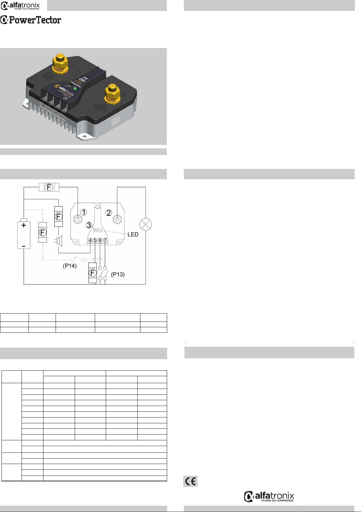
(1) - Input Positive (4) - Alarm** (7) - Switch
(2) - Output Positive (5) - Ground (F)- Fuses
(3) - Program (6) - Override
WIRING DIAGRAM
ENGLISH • FRANÇAIS • DEUTSCH • ESPAÑOL ASSEMBLAGE
PROGRAMMATION
T E L: +44 (0) 1202 715 517 • sales@alfatronix.com
CONTENU
1 x PowerTector 3 x Vis
6 x Bornes Plates Encliquetables 1 x Fil de programmation
CARACTERISTIQUES
Sélection automatique du mode 12 V / 24 V (mode 12 V, 8<V≤17, mode 24 V, 17<V≤35)
10 réglages de tension programmables
Fourni avec des bornes plates encliquetables FASTON
Indice de protection IP65
Connexion pour commutateur marche / arrêt à distance
Raccord de l'interrupteur de dérivation
Connexion pour alarme à distance
FONCTIONNEMENT
Le PowerTector protège contre toute décharge excessive de la batterie en déconnectant la charge avant que la tension de la
batterie n’atteigne un niveau trop faible. Dix seconde après que la tension de la batterie chute en-deçà du seuil de déconnexion,
la sortie de l’alarme s’active. Si la tension de la batterie reste inférieure au seuil de déconnexion après une période totale de 60
s,le PowerTector déconnecte la charge de la batterie et désactive l’alarme.
La charge reste déconnectée jusqu’à ce que la tension de la batterie dépasse le seuil de reconnexion.
Le PowerTector protège la charge en la déconnectant lorsque la tension de la batterie excède 19 V sur un système 12 V ou 32 V
sur un système 24 V.
system.
ASSEMBLAGE
1. Sélectionner un endroit frais et aéré pour installer le dispositif. Ne pas exposer à la lumière directe du soleil.
2. Monter aussi près que possible de la batterie en utilisant un fil de diamètre suffisant.
3. Isoler l’alimentation du câblage avant de démarrer l’installation.
4. Monter via les trois orifices de fixation en utilisant des vis ou des boulons.
5. Connecter le terminal « terre »
6. Connecter le terminal « entrée positive ».
7. Si nécessaire, programmer l’unité en suivant les consignes ci-dessous.
8. Connecter la « sortie positive » une fois la programmation achevée.
9. Si nécessaire, raccordez l'alarme et les interrupteurs.
La fonction de dérivation peut être utilisée pour forcer le PowerTector à se reconnecter à la sortie pendant 4 minutes, pour pouvoir
réaliser des mesures d'urgence. Ceci ne fonctionne que si la tension électrique de la batterie est supérieure à 8,5 V. Pour utiliser la
fonction de dérivation, connectez la borne de « dérivation » à la borne négative de la batterie pendant 10 secondes, et le
PowerTector se reconnectera à la sortie. Retirez à présent le raccord entre la borne de « dérivation » et la batterie. Pour opérer
l'installation de dérivation, nous vous conseillons d'utiliser un bouton-poussoir à rappel.
LA CONNEXION
Isoler le circuit avant de connecter ou de déconnecter le dispositif. Raccorder l’unité conformément au schéma de
câblage.
PROGRAMMATION
Il y a quatre paramètres qui peuvent être définis par l’utilisateur, chaque paramètre fait partie d’une famille de pro-
grammes, comme indiqué dans la table ci-dessous. Le changement d’un paramètre à l’intérieur d’une famille de pro-
grammes n’affecte pas les autres familles de programmes.
Famille de programmes 1: Gamme de tension de fonctionnement. P1-P10 (P7 est le programme par défaut).
Famille de programmes 2: le mode de sortie Alarme. (P11 est le programme par défaut). La sortie alarme sera active en
continu, 10 secondes après que la tension soit tombée en dessous du seuil de déconnexion. Elle sera desactivée si la
tension passe au-dessus du seuil de déconnexion ou 60 secondes après que la tension soit tombée en dessous du seuil de
déconnexion.
L’alarme sera activée en mode impulsion si la tension de la batterie passe au dessus de 19V pour un système 12V ou
32V pour un système 24V.
P12 –La sortie alarme sera active en continu, 10 secondes après que la tension soit tombée en dessous du seuil de
déconnexion. Elle sera desactivée si la tension passe au-dessus du seuil de reconnexion.
La sortie alarme ne sera pas activée si la tension passe au-dessus du niveau de protection de surtension.
Ce mode peut être utilisé pour activer un chargeur de batterie externe pour remplir de nouveau la batterie que le Power-
Tector protège.
Famille de programmes 3: Commuter mode terminal P13 (default)—La sortie du PowerTector se déconnecte lorsque le
terminal du commutateur est connecté au terminal négatif de la batterie.
P14—La sortie du PowerTector se déconnecte lorsque le terminal du commutateur est connecté au terminal positif de la
batterie.
Famille de programmes 4: Sélection de la gamme de tension. P15 (programme par défaut) –l’unité sélectionnera au-
tomatiquement la gamme de tension (12V ou 24V) chaque fois que la tension sera appliquée.
P16 –L’unité fonctionnera comme une unité 12V uniquement.
P17 - L’unité fonctionnera comme une unité 24V uniquement.
Pour modifier un programme :
1. Connecter de manière provisoire le terminal « entrée positive » et le terminal de « programmation » en utilisant le fil
de programmation fourni.
2. La LED commence à clignoter, chaque clignotement indiquant le programme à sélectionner.
3. Maintenir la connexion jusqu’à ce que le nombre de clignotements de la LED corresponde à celui du programme
souhaité, puis retirer la connexion.
4. La LED clignote un même nombre de fois pour confirmer la sélection du programme.
Alarme** - L'utilisation d'un relais nécessite une diode de roue libre pour empêcher tout dommage - cf. Note d'applica-
tion AN-PT01.
FRANÇAIS
L’appareil est conforme aux exigences de la Directive UE 2004/108/CE. La plaquette d’identification se
trouve sur le haut de l’appareil.
SÉCURITÉ
SECURITE
Ce PowerTector est exclusivement pour des équipements accessoires. Il ne doit absolument pas être utilisé pour décon-
necter un équipement essentiel à la sécurité du fonctionnement du véhicule.
Tenir l’appareil éloigné de tout choc mécanique.
Ne pas exposer l’appareil à des températures extrêmes, au soleil direct ou à d’importantes vibrations.
L’appareil ne doit être utilisé que dans un environnement sec, comme un véhicule.
Ne pas installer l’appareil dans un véhicule à haute température et prenez garde que l’espace entourant l’appareil soit
assez large pour qu’il puisse être ventilé et se refroidir.
La sangle de connexion doit être protégée par des fusibles.
Veillez à la puissance électrique et la polarité de la tension de sortie lors de l’installation. Une polarité incorrecte de
sortie pourrait entraîner des dommages du circuit.
Isoler le circuit avant de connecter ou de démonter l’appareil.
Assurez-vous que la sortie de l’appareil n’est pas court-circuitée.
Ne jamais ouvrir l’appareil ou tenter de le réparer. L’appareil doit être remplacé en cas de dommage.
MODES DE PROGRAMMATION
29 Newtown Business Park, Poole, BH12 3LL, UK • www.alfatronix.com
FUSIBLE
Le fusible d’entrée et de sortie doit être connecté de façon appropriée.
Pour la terre, entre 500 mA minimum et 1 A maximum.
Référence Courant Tension nominale Dimensions Poids
PT100 100A 12V/24V 124x97x51mm 530g
PT200 200A 12V/24V 124x97x51mm 530g
CARACTÉRISTIQUES TECHNIQUES
MODES DE PROGRAMMATION
* Réglages par défaut
(1) - Entrée positive (4) - Alarme** (7) - Commutateur
(2) - Sortie positive (5) - Terre (F)- Fusibles
(3) - Programme (6) - Basculer
SCHÉMA DE CÂBLAGE
FRANÇAIS
MODE D'EMPLOI POUR L'OPÉRATION & LE MONTAGE
PT100 & PT200
vK
INDUCTIVE LOADS
The inductive load rating of this PowerTector is 1mH.
Do not exceed the specified inductive rating.
Inductive equipment includes; motors, pumps, refrigeration, relays, long cables etc.
Conducted voltage transients must not exceed those specified by ISO7637-2:2004 Level III.
INDUCTIVE LOADS
The inductive load rating of this PowerTector is 1mH.
Do not exceed the specified inductive rating.
Inductive equipment includes; motors, pumps, refrigeration, relays, long cables etc.
Conducted voltage transients must not exceed those specified by ISO7637-2:2004 Level III.
Programme
famille
Numéro de
programme 12V 24V
Déconnecter Reconnecter Déconnecter Reconnecter
Famille 1
P1 10.5V 12V 21V 24V
P2 10V 11.5V 20V 23V
P3 9.5V 11.5V 19V 23V
P4 11V 13.5V 22.5V 26.5V
P5 11.5V 13.5V 23V 27.5V
P6 10.5V 12.5V 21V 25V
P7* 11.5V 12.5V 23V 25.5V
P8 11V 12.5V 23.5V 25.5V
P9 12V 13V 24V 26V
P10 10V 13V 20V 26.5V
Famille 2
P11*Mode alarme = Normal
P12 Mode alarme = Activation du chargement de la batterie
P13* Mode commutateur = Faible
Famille 3 P14 Mode commutateur = Élevé
Famille 4
P15* Gamme de tension= Auto
P16 Gamme de tension= 12V uniquement
P17 Gamme de tension= 24V uniquement
Program
Family
Program
Number 12V 24V
Disconnect Reconnect Disconnect Reconnect
Family 1
P1 10.5V 12V 21V 24V
P2 10V 11.5V 20V 23V
P3 9.5V 11.5V 19V 23V
P4 11V 13.5V 22.5V 26.5V
P5 11.5V 13.5V 23V 27.5V
P6 10.5V 12.5V 21V 25V
P7* 11.5V 12.5V 23V 25.5V
P8 11V 12.5V 23.5V 25.5V
P9 12V 13V 24V 26V
P10 10V 13V 20V 26.5V
Family 2
P11*Alarm Mode = Normal
P12 Alarm Mode = Battery Charger Enable
P13* Switch Mode = Low
Family 3 P14 Switch Mode = High
Family 4
P15* Voltage Range = Auto
P16 Voltage Range = 12V Only
P17 Voltage Range = 24V Only


