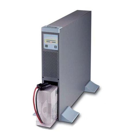
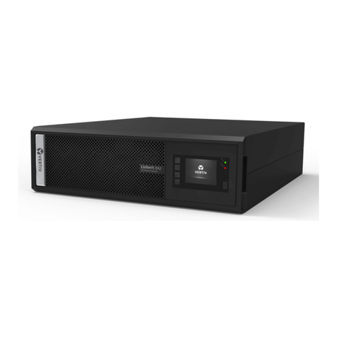
Chloride Cool Power 600 User manual


CHLORIDE
POWER PROTECTION
o Uninterruptible Power System
o Unterbrechungsfreie Stromversorgung
o Sistema de Alimentación Ininterrumpida
o Alimentation Sans Interuption
o Sistema Statico di Continuita
o Sistema de Fornecimento de Energia Initerrupto
Cool Power 600
900
1200
1600
Operating Manual
Bedienungsanleitung
Manual de usuario
Manuel utilisateur
Manuale d’Uso
Manual de instruçöes

All rights, including rights of translation, reproduc-
tion by printing, copying or similar methods, even
of parts, are reserved.
Offenders will be liable for damages.
All rights, including rights created by patent grant
of registration of utility model or design, are reser-
ved.
Delivery subject to availability. Right of technical
modification reserved.

Safety Instructions 7
Caution 7
Explicación de símbolos 8
1. Introduction 9
2. Unpacking the Unit & Contents 10
2.1 Unpacking the Unit 10
2.2 Package Contents 12
3. Installation 12
4. Display and Operating Components 15
4.1 Front view 15
4.2 Rear view 16
5. Equipment Operation 18
5.1 Working modes 18
5.2 Indicator lights 18
5.3 Push button Operation 19
5.4 Acustical signals 20
5.5 Voice and Data Lines Protection 20
6. Description of Communication Interfaces 21
6.1 Standard COM Interface 21
6.2 SNMP Adapter 22
6.3 Cable 59 22
6.4 Cable 61 22
7. Mantenance 23
7.1 Storage 23
7.2 Cleaning 23
8. Troubleshooting 24
9. Technical Data 25
10. Backup Times 26
11. Registration Form 27
12. Chloride Address 29
5
REV: 16/03/01
Operating Manual
945012.066

6945012.066REV: 16/03/01
Operating Manual

Safety Instructions
Read the following information carefully!
The failure to follow these instructions could endanger your life, your health, the operation of
the equipment or the security of data.
- The UPS satisfies safety regulations relative to information systems and electronic machines used
in offices. If you have any questions, contact your after sales service.
- Use the right packaging for transport (protection against bumps and blows).
- The unit is equipped with a power line in compliance with safety norms and should only be connec-
ted to a grounded plug.
- The button (see chapter entitled “Button operation) does not insulate the unit from the mains.
In the event of a disconnection of mains voltage, the built-in battery will continue to supply energy to
the load.
- The power cords should be arranged in such a way as to prevent people from stepping on them or
tripping over them. When installing the unit, follow the instructions in the chapter on “Installation and
Operation”.
- Data transmission lines should not be connected or disconnected during storms.
- Prevent objects from falling into the equipment (necklaces, paper clips, etc.).
- In the event of an emergency (deterioration of the case, control or line element, penetration of liquids
or foreign bodies), disconnect the equipment, remove the connection to the mains and call your after
sales service.
CAUTION:
1. The equipment must be at least 10 cm away from the wall
2. Make sure there are no objects blocking the vent.
3. Do not place the unit near heat sources or in places exposed to direct sunlight, dust, water or
mechanical blows.
4. The equipment should only be installed in areas where the temperature is controlled and free of
conductive contaminants.
5. Use approved connection cables which support at least the voltage and intensity specified on each
model.
6. The incoming and outgoing wires must always be accessible to the user.
7. In compliance with the eletromagnetic compatibility standard (EN 50091-2) the total length of the
output cables must not exceed 10m. Likewise, the communication cables must not exceed 3 m. in
length.
8. The sum of the leakage current of the loads connected to the UPS should not exceed a total of
2.8mA.
9. Before disconnecting the UPS from the mains, disconnect the output cables connected to the load.
10. Never open the equipment. It should only be opened by qualified technical personnel. It contains
elements which have a charge even with the equipment turned off.
7
REV: 16/03/01
Operating Manual
945012.066
!

WARNING: There is a high risk of electrical “shock” from the battery and a high short-circuit intensity.
Remove all watches, rings and other metal objects and use only insulated tools when
replacing the battery.
WARNING: Do not expose the battery to fire; it can explode.
WARNING: Do not open the battery. The electrolyte can be dangerous to the eyes and skin when spi-
lled. It may be toxic.
Explanation of Symbols
The meaning of the symbols used in this manual are the following:
The failure to follow these instructions could endanger your life, your health, the operation of
the equipment or the security of data.
The author proposes supplementary information and advice.
The text below describes the procedure to be followed.
8REV: 16/03/01
Operating Manual
945012.066

1. Introduction
Installed between the mains and the load, the Uninterrupted Power System (UPS) protects electroni-
cally sensitive equipment against disturbances and particularly against electric power failures.
This UPS works on the Line Interactive principle. This means that the connected equipment is powe-
red from the mains after passing through a voltage stabilizer and diverse filters. This reduces distur-
bance from the mains which in turn increases the safety level of equipment operation (PCs, servers,
distributed systems, etc.). In the event of a mains failure, the built-in, maintenance-free battery assu-
mes the uninterrupted supply of energy to the connected equipment. The energy from the UPS ena-
bles the system to keep working until the mains power returns or, in the event of a prolonged outage,
the UPS will inform the user when all processes must be terminated and the system shut down.
The UPS indicates by acoustical (buzzer) and optical (LED) alarms that a mains failure has occurred
or persists in order to end all tasks as necessary.
These operating instructions contain all of the information necessary for the installation and operation
of the UPS.
The UPS has an auxiliary outlet with a filter for surges, electrical noise and transient voltage for non-
critical loads which is not battery-powered.
This UPS is equipped with a protection device for voice and data lines patented by ONEAC
Corporation. It protects fax, modem or local network boards from cable disturbances (noise and dan-
gerous voltage peaks). This protection device improves the quality of communications by accelerating
data transmissions and eliminating static from voice calls.
9
REV: 16/03/01
Operating Manual
945012.066

2 Unpacking the Unit and Contents.
Upon receipt of the unit and prior to unpacking it, make sure that there are no visible signs of dama-
ge on the outside of the box. If any damage is observed, notify the carrier.
Also observe the date of the last recharge which is located on the side of the box (see Figure “A”). Not
the reception date of the equipment and recharge the battery once the equipment has been unpac-
ked.
Figure A.
2.1 Unpacking the Cool Power
The procedure for unpacking the unit is described below:
10 945012.066REV: 16/03/01
Operating Manual
1.- There should be a clean, obstacle-free
surface available for unpacking the
equipment.
2.- Open the box, remove the documen-
tation and cables (manual, power
cords and communication cables).

11
REV: 16/03/01
Operating Manual
945012.066
3.- Place the equipment on the open side
of the box, leaving the flaps of the box
open underneath the equipment.
5.- Remove the protective materials from
the unit. 6.- The equipment is now ready for con-
nection and start-up.
4.- Lift the box off.

2.2 Contents:
- UPS unit:
- 2 power cables for - Communication cord:
connection to UPS outlet
- User manual. – Registration and software download card:
3. Installation
No prior knowledge is required to install this equipment.
1. Connect the outlets on the back of the UPS to the equipment to be protected using the IEC320 type
cables for the 230V model or NEMA 5-15R for the 115V model. Make sure that the total connected
load does not exceed the useful power range of your UPS.
12 945012.066REV: 16/03/01
Operating Manual

2. Connect the selected load (i.e. printer, scanner) to the surge protected outlet. Appropriate loads are
those elements that demand surge protection, but that do not require extended runtime during power
outages.
3. If monitoring software is to be used, connect the comm cable between the UPS COM port (DB-15)
and the computer’s COM port (DB-9).
4. Connect the power cord to the UPS.
5. Plug the power cord into the mains. The computer’s power cord may be used.
13
REV: 16/03/01
Operating Manual
945012.066

6. Once connected to the mains, check to make sure that the LED on the front panel is green within
a few seconds. Immediately after connecting the UPS to the AC network the equipment runs a self-
test. If the test is successful and the electricity supply is within the specified limits, the equipment will
start up and will supply energy to the output connectors.
7. Start up the protected equipment.
The voice and data line is connected for protection as shown on the input and output on the equip-
ment panel.
When the equipment is started, the batteries in the UPS are automatically charged. The UPS may be
used immediately even through the batteries have not been fully recharged. In this case, however, the
maximum residual capacity will not be available (complete discharge time).
Before running any tests, the batteries must be recharged for at least 6 hours.
Do not connect any equipment which could overload the UPS or draw continuous current from
the UPS (e.g.: hair driers, vacuum cleaners, etc.).
The UPS may be used even without being connected to the mains. To do so, the batteries must
be sufficiently charged. See “Button Functions”.
14 945012.066REV: 16/03/01
Operating Manual

4. Display and Operating Components
4.1 Front View
All of the models in this range have the same display element located on the front panel. They are as
follows:
1. Battery level : Indicates the charge level of the battery. For more information see Part 5.2.
2. Working status : The color green indicates that the network is within the tolerance limits; the
color red indicates that it is outside of the acceptable limits. more information
see Part 5.2.
3. Alarm indicator : The color red indicates an overload or temperature alarm. For more informa-
tion see Part 5.2.
15
REV: 16/03/01
Operating Manual
945012.066
Alarm indicator
Battery level
Operating status

4.2. Rear View
Depending on the model and the power, the elements may be arranged differently on the rear panel..
Each one of the models is described below:
16 945012.066REV: 16/03/01
Operating Manual
1
2
3
4
5
6
7
Cool Power 600 230V
1
2
3
4
5
6
7
Cool Power 900/1200 230V
1
2
3
4
5
6
7
Cool Power 600 115V
1
2
3
4
5
6
7
Cool Power 900/1200 115V

1. Battery test : This button enables you to run a battery test, switch off the UPS and restart
it without mains electricity. For more information see Part 5.3.
2. Communication Port : Basic (signals) and advanced (using RS232 protocol) communication port.
For more information see Part 6.
3. Telephone and data
line protection : Filtering of electric noise on data transmission lines. For more information
see Part 5.5
4. Battery protected and
filtered outlet : Outlet protected for critical loads requiring additional electricity.
5 Filtered outlet : Outlet protected against surges for non-critical loads.
6. Input : IEC type connector for connecting the power cord of the protected load.
7. Circuit breakers : Protects against short-circuits, electronic fuse with reset.
17
REV: 16/03/01
Operating Manual
945012.066
12
3
4
5
6
7
Cool Power 1600 230V Cool Power 1600 115V
12
3
4
5
6
7

5. Equipment Operation.
5.1 Working modes.
This UPS works automatically without the use of a switch. It starts up automatically when there is
power from the mains.
When the electricity is within acceptable frequency and voltage margins, the LED on the front
panel is green and the equipment recharges the battery. When outside of the acceptable margins, the
LED is red and uses power from the battery to supply protected critical equipment.
To shut down the equipment, simply shut down the protected equipment. When there is no electricity
from the mains, if the UPS does not detect any usage it shuts down automatically within 30 seconds.
This makes it possible to shut down the general power supply without wearing down the batteries.
See special push button functions for starting up and shutting down the UPS. Part Aptdo. 5.3
NOTE: When the unit is switched off it goes into a stand-by mode during which it draws energy from
the batteries to keep the electronics working for a certain period of time while waiting for the power to
return. If the power failure lasts longer than the allowed stand-by time, the equipment will shut down
completely. When the power comes back, the process will be similar to start-up.
This UPS has a three-stage output voltage regulator: trim, central and boost.
This ensures a wide range of input voltages (without having to run down the battery) and at the same
time that the output voltage is always within acceptable margins. This guarantees that the batteries
are recharged even with anomalous input voltages while protecting the connected equipment. To
ensure maximum autonomy following a total battery rundown, the UPS must be charges for at least 6
hours.
The unit is equipped with a “circuit breaker with reset” for overload protection. If the circuit breaker
trips, remove the cause of the overload and rest the circuit breaker.
5.2 Indicator Lights.
The indication lights on the front panel enable fast and easy identification of the operating status of
the equipment. The different elements are described below:
18 945012.066REV: 16/03/01
Operating Manual

· The green LED indicates that the equipment is working in line mode.
The red LED indicates that the equipment is working in battery mode,
powering the protected equipment from the battery.
· This LED indicates an alarm. A blinking red light indicates that the
equipment has shut down due to the persistence of an alarm. Try to
ascertain he cause of the alarm (temperature or overload).
Red LED statuses:
Off: no alarms.
Solid red: equipment with alarm (acoustical also).
Blinking red: the equipment has shut down due to a persistent alarm.
· A set of LEDs which indicates the estimated recharge status of the bat-
teries at all times, indicating the following levels: 25, 50, 75 and 100%.
If these LEDs are blinking it means that the battery is defective after
having run a battery test. In this case, the batteries must be recharged
for at least 6 hours followed by another battery test. If the same battery
failure occurs at this point, the batteries must be replaced.
NOTE: only applies to 115V models: There is an indicator on the rear panel of a defective grounding
connection. If this indicator is lit, the electrical installation should be checked (On the Rack version,
this indicator light is located on the front panel).
5.3 Push Button Operation
On the rear panel of the equipment there is a “push button” which performs several different functions
depending on the initial status of the equipment (In the Rack version the button is located on the front):
· If the equipment is operating normally, pressing the button for approxi-
mately 2 seconds will test the batteries.
. If the equipment is operating normally and the button is held down for
more than five seconds, the unit will shut down and move into a stand-
by mode (The equipment will restart at the end of the configured stand-
by time if there is power from the mains in order to prevent the battery
from being completely worn down) Attention: it is not a real permanent
shutdown.
· If the UPS is turned off and the button is pressed for more than 2 seconds, the unit will start up and
provided output voltage which will come from the batteries when there is no mains power and the bat-
teries are sufficiently charged.
19
REV: 16/03/01
Operating Manual
945012.066

5.4 Acoustical signals
In the event of any anomaly or notable event, the UPS has a buzzer which emits a series of beeps.
The acoustical signals will depend on the operating status of the equipment. The different situations
in which the buzzer may be activated are as follows:
- Battery Mode: One «beep» every 15 seconds indicates that the voltage is outside of the window
of tolerance and the UPS is powering the protected load with battery power.
- Self-Test Mode: A series of five «beeps» every 5 seconds. The UPS runs an internal self-test
when turned on.
- Pre-Alarm Mode: One «beep» every second, ongoing. The UPS indicates that the battery is
almost completely worn down and that its autonomy is about to come to an end.
- Historical Mode: Two «beeps». An event has occurred which is registered and memorized in the
“HISTORICAL” log.
- Alarm Mode: Four short «beeps» and one long «beep» per second. A user alarm has gone off
(overload or temperature).
5.5 Voice and Data Line Protection.
The UPS Cool POWER models includes a protective filter for voice and data lines. The load is thus
protected not only against electrical disturbances (UPS) but also against potential anomalies in the
voice and data lines which can damage the protected load (protective filter for communications).
This filter has been designed and patented by the prestigious ONEAC Corporation, a member of the
CHLORIDE POWER PROTECTION Group.
Patent Nº:
US 4.758.920
CAN 1.286.812
EPC 388.107(UK, FRA)
GER P3861679.3
AUSTRALIA 593.437
20 945012.066REV: 16/03/01
Operating Manual
Telephone Line / TLP Data Line / DLP
* Typical values
10/1000µs,1.5kV, 75 A 10/100µs, 1.5kV
520V * 50 A 35V *95V * 100 A 65V *
0-1kV 100V/s
520V *
320V* 7,5V *
12 a 18
Ω≤
0.5
Ω
≥
150 mA
< 1 ns < 5 ns
> 100 M
Ω
> 50 k
Ω
50Vcc, 1Vca, 10kHz-1MHz 0Vcc, 1Vca,1MHz
< 200pf
< 200pf < 50pf
300 mA
1A
< 5V
±
10 A
±
75 A
Input impulse
Unlimited
Unlimited
-40ºC to 65ºC
-40ºC to 85 ºC
Operating temerature
Storage temperature
With impulses of 10/1000
µ
s
Service life
Impulse between A and B
Break voltage Vcc
Impulse between A and B
Loop resistance
Permanent current
Response time
Insulation resistance
Ground line capacity
Impulse between A and B
Surge protection
Without reset (fuse with delay)
Operating voltage (1A)
This manual suits for next models
3
Table of contents
Other Chloride UPS manuals

Chloride
Chloride LP061XHR Operator's manual
Chloride
Chloride CP3000 Series User manual
Chloride
Chloride EDP70 Instruction Manual

Chloride
Chloride EDP70 Instruction Manual
Chloride
Chloride Desk POWER 300 User manual
Chloride
Chloride SYNTHESIS User manual
Chloride
Chloride Desk Power Plus 1000 User manual

Chloride
Chloride Power Star User manual

Chloride
Chloride ACTIVE A0K7XAU User manual

Chloride
Chloride SE041XAT Operator's manual
