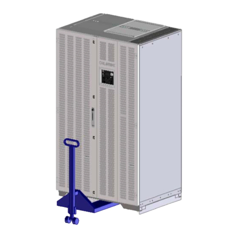
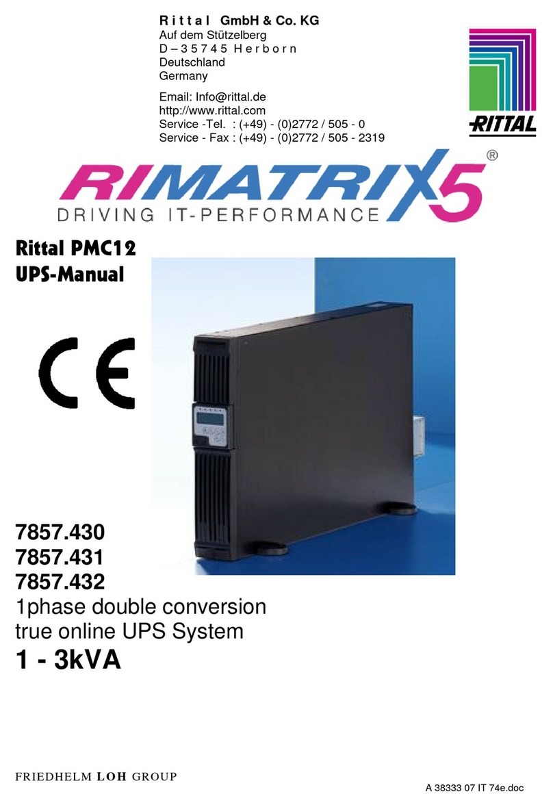
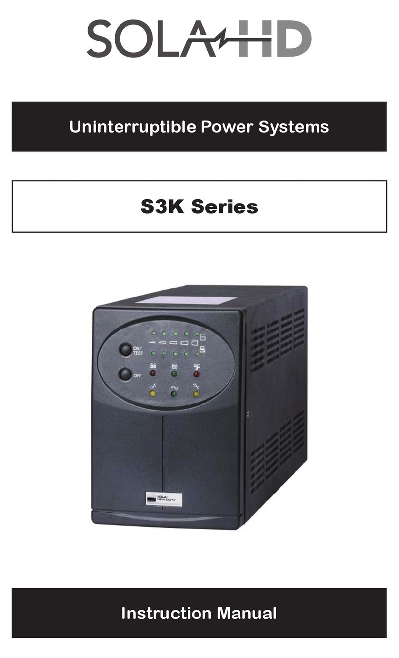
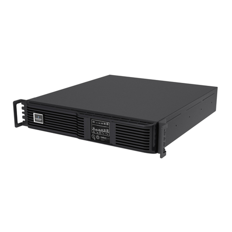
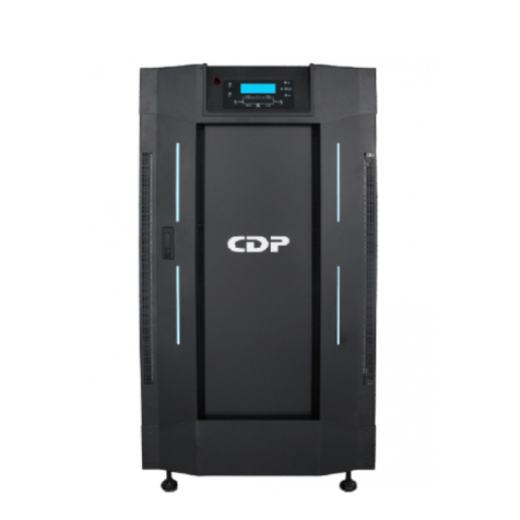
Chloride CP3000 Series User manual

CHLORIDE POWER PROTECTION
THREE-PHASE Uninterruptible Power System
Owner’sManual
CP3000
Series
P/N 913-537 REV C

ii
UserandOperatingManual
©Chloride Power Protection
28430 North Ballard Drive • Lake Forest • IL • 60045
Toll Free Phone 800-239-2257 • Toll Free Fax 800-833-6829
Phone 847-990-3228 • Fax 847-549-7917

iii
DECLARATION OF CONFORMITY
The manufacturer: CHLORIDE POWER PROTECTION
Head office at:
28430 North Ballard Drive
Lake Forest, IL 60045
USA
HEREBY DECLARES THAT THE PRODUCT: CP3000
CONFORMS TO THE FOLLOWING REGULATIONS:
UL1778
FCC PART 15

iv
IMPORTANT SAFETY INSTRUCTIONS
SAVE THESE INSTRUCTIONS
THIS MANUAL CONTAINS IMPORTANT INSTRUCTIONS FOR THE CP3000 SERIES THAT
SHOULD BE FOLLOWED DURING INSTALLATION AND MAINTANANCE OF THE UPS,
BATTERIES, OPTIONS AND ACCESSERIES

v
TableofContents
INTRODUCTION
Declaration of conformity iii
Safety vii
Grounding the unit viii
FCC compliance xi
CHAPTER 1
DELIVERY AND STORAGE
Delivery 1
Unpacking 1
Handling 2
Storage 3
CHAPTER 2
PREPERATIONS FOR INSTALLATION
Environmental Conditions 4
Accessarea 5
Floor loading 6
CHAPTER 3
INSTALLATION
Installation data 7
Specifications 8
Suggested cable sizes 9
Terminations 10
Protection devices 11
Electrical connections 12

vi
Chapter 4
BATTERY
Battery connections 16
Chapter 5
OPERATION
Displaypanel 20
Indicators and buttons 21
Menu Structure 23
Menus 24
Warnings and Faults 29
Maintenance by-pass switch and power control unit breaker 30
Operatingmodes 31
Operational procedures 32
Chapter 6
COMMUNICATIONS
Interfaceslots 33
Communication slot adaptability 34
RAU/RLY/DRV 35
AS400 36
RS232 37
ManageUPSnet 38
LIFE 2000 39
Industrialcontacts 40
Chapter 7
MAINTENANCE 41

vii
Safety (English)
WARNING:
This equipment services power from more than one source. The convenience receptacles may have voltage
even when the unit is off. UPSs present a different safety issue than most electrical equipment because
removing input power from the UPS puts it into backup mode. Removing the input power from the UPS does
not remove the electrical charge. To ensure that the UPS is off, turn the inverter OFF before removing the
input power from the UPS.
CAUTION:
Operating this equipment without proper grounding may present a risk of electrical shock.
WARNING:
Dangerous voltages are present within this unit! There are no user-serviceable parts inside. Any repairs or
modifications by the user may result in out-of-warranty repair charges, unsafe electrical conditions, or
violation of electrical code. Do not remove the cover. All repairs should be done by qualified service
personnel. Voltages inside the UPS may be lethal. Internal components are powered even when the power
switch is in the OFF position. Even with the battery disconnected and the unit unplugged, energy is stored in
high voltage capacitors and represents a severe shock hazard.
Other Safety Considerations:
The system is not intended for outdoor use. The operating environment should be maintained within the
parameters stated in the manual. Keep the cabinet doors closed and locked to ensure proper cooling airflow
and to protect personnel from dangerous voltages inside the unit. The UPS system contains its own power
source. Lethal voltages are present even when the UPS is disconnected from utility power.
If service or routine maintenance is required:
Ensure all power is disconnected before performing installation or service. Ensure the area around the UPS
system is clean and uncluttered. Battery maintenance or battery replacement should be performed only by
authorized service personnel.
Observe all DANGER, CAUTION and WARNING notices affixed to the inside and outside of the
equipment.
Battery Disposal UPS batteries contain toxic and acidic materials. Disposal method must adhere to
local/national recycling laws. Dispose of the battery in one of three ways:
ATTENTION: The batteries in this UPS are recyclable. Dispose of the batteries properly.

viii
CAUTION: DO NOT dispose of batteries in a fire. The battery may explode. Do not open or
mutilate the battery or battery cabinet. Released electrolyte is harmful to the skin and eyes and is toxic.
WARNING:
Only AUTHORIZED SERVICE PERSONNEL should perform maintenance on or service the UPS system.
Grounding the Unit
CAUTION:
Interruption of the protective grounding conductor or disconnection of the protective earth terminal presents a
potential shock hazard that could result in personal injury and damage to the equipment.
WARNING:
1) An insulated grounding conductor that is identical in size, insulation material, and thickness to the
grounded and ungrounded branch circuit conductors except that it is green with or without one or more
yellow stripes is to be installed as part of the branch circuit that supplies the unit or system.
2) The grounding conductor supplied in 1) is to be grounded to earth at the service equipment or, if
supplied by a separately derived system, at the supply transformer or motor-generator set.
3) The attachment-plug receptacles in the vicinity of the unit or system are all to be of a grounding type,
and the grounding conductors serving these receptacles are to be connected to earth ground at the service
equipment.

ix
FCC Compliance
ATTENTION:
Changes or modifications to this unit not expressly approved by the party responsible or in FCC compliance
could void the user’s authority to operate the equipment. This equipment was tested and complies with the
limits for a Class A digital device, pursuant to Part 15 of FCC Rules. These limits are designed to provide
reasonable protection against harmful interference when the UPS is operating in a commercial environment.
The UPS generates, uses, and can radiate radio frequency energy. If installation and use is not in accordance
with the instruction manual, it may cause harmful interference to radio communications.
ATTENTION:
Operation of this equipment in a residential area may cause harmful radio communications interference. The
user is responsible for correcting the interference.
The basic environmental requirements of the UPS system are:
Ambient Temperature Range: 32 – 104°F (0-40°C)
Recommended Operating Range: 68 – 77°F (20-25°C)
Maximum Relative Humidity: 95% (non-condensing)

1
DELIVERYAND STORAGE
DELIVERY
The goods have been checked thoroughly before dispatch. Immediately inspect upon receiptof thepackaging and ensure that thecontents
are undamaged. A SHOCKWATCH label has been affixed to the packaging. Red indicator indicates rough handling. If red, Note on Bill
of Lading and report immediately to the freight forwarder.
UNPACKING
Care should be taken when removing the packaging in order to avoid damaging the equipment. Check all packaging materials to ensure
that no items are discarded. Remove the packaging following the sequence illustrated in figure 1. Shipping brackets are attached to the UPS
or battery cabinets and skid. Remove the brackets by removing the shipping bolts attached to the skid and UPS or battery cabinet/s.
Figure – 1
Shipping and Handling the UPS
Chapter
1
PACAKAGING
BRACKETS ON
BOTH SIDES
REMOVE PACKAGING
SHIPPING
BOLTS
PALLET

2
HANDLING
The equipment must be kept upright at all times and handled with care. Damage may be caused if subjected to severe impact. The UPS and
battery cabinet has been fitted with casters to allow ease of installation. It is recommended that the UPS and Battery cabinets be moved with a
pallet jack or fork lift over long distances. The side skirts have been intentionally left off to allow fork access under the UPS or battery cabinets.
See figure 2.
Figure – 2
Handling the UPS

3
STORAGE
When the UPS is not used within seven days of delivery, please pay special attention to the storage requirements.
If the batteries or the equipment is to be stored, they must be kept in a clean, dry environment and away from extremes of
temperature.
STORAGE DATA
Storage temperature range: -4°F (-20°C) to 140°F (60°C); however, batteries should not be exposed to temperature above
77°F (25°C). Each increment of 15°F (8°C) above 77°F (25°C) reduces the expected battery life by 50%. See battery
manufacturer’s recommendations.
The ideal environmental temperature range is 59° F to 77° F due to the battery life design at 77 F. Each increment of 15 °F
above 77 °F reduces the expected battery life by 50%. See battery manufacturer’s recommendations.
UPS without batteries -4°F to 140°F (-20°C to 60°C)
Relative humidity from 0% to 95%
UNLESS BATTERY MANUFACTURER’S SPECIFICATION STATES
OTHERWISE

4
PREPERATIONS FOR INSTALLATION
ENVIRONMENTAL CONDITIONS
The UPS and battery cabinets must be installed vertically, on a level and even surface. The UPS and battery cabinets must be
protected from extremes temperatures, water, humidity, and the presence of conductive powder or dust. Do not stack units and do
not place any objects on top of the unit. Although the functional temperature range of the UPS is 32°F to 104°F (0°C to 40°C).
The ideal environmental temperature range is 59°F to 77°F (15°C to 25°C) due to the battery life design at 77°F (25°C). Each
increment of 15°F above 77°F reduces the expected battery life by 50%. See battery manufacturer’s recommendations.
Chapter
2

5
ACCESS AREA
The area must have sufficient space for the installation to be carried out. Access doors must be sufficiently large to permit passage
of the unit. The UPS has been designed to provide front access for maintenance purposes. See figure 3.
Figure – 3
T
OP ENTRY PLATE
FAN EXHAUST
STATIONARY CASTERS
SWIVEL CASTERS
69.0’
38.6’
TOP
BAC
K
FRONT SIDE
BOTTOM
27.6’

6
FLOOR LOADING
It is necessary that the floor in the chosen location be capable of supporting the weight of the UPS and battery cabinets. The
weight of these cabinets can be found in table 1.
To ease movement over short distances the UPS is fitted with casters. See figure 4.
Figure – 4
Floor assembly for ease of movement
CASTERS
LEVELING
BOTTOM CABLE ENTRY
PLATE
BOTTOM

7
INSTALLATION
Installation must be carried out only by qualified electricians and in conformity with the applicable safety
standards.
UNLESS MANUFACTURER’S SPECIFICATION STATES OTHERWISE
INSTALLATION DATA
Ambient temperature 32°F to 104°F (0°C to 40°C)
Relative humidity (w/o condensing at 20°C) 0 – 95%
Max. Altitude (w/o de-rating) 5000 ft a.s.l.
Cable entry top or bottom
Air inlet front & bottom
Air outlet rear
Chapter
3

8
UPS with standard autonomy
Table 1 – SPECIFICATONS
Unit UPS power rating
kVA 10 15 20
DESCRIPTION
kW 8 12 16
Voltage Vrms 208 480 480 208 480 480 208 480 480
Max Current Arms 40 17 17 53 23 23 66 29 29
INPUT
Frequency Hz 60
Voltage Vrms 208 208 480 208 208 480 208 208 480
Current Arms 28 28 12 42 42 18 56 56 24
Frequency Hz 60
BY-PASS
OUTPUT
Wave form - SINUSOIDAL
Maxi dissipation @ nominal load and battery in
recharge BTU/Hr 4443 6118 8150
Battery End-of-Discharge Adc 28 42 55
Mechanical data
Length Inches 38.6
Width Inches 27.6
Height Inches 69.0
Weight (without batteries and input filter) Lbs 850
Weight (with standard autonomy) Lbs 1590
Maximum noise level @ 3 ft dBA 55
-For safety, ratings see label.

9
SUGGESTED CABLE SIZES
•Input and output conductors are based on NEC 310-16 for insulated copper conductors rated at 75°C in ambient
temperature of 104°F.
•Grounding conductors are based on NEC 250-95 for copper wire.
•UPS input and output cables should be run in separate conduits.
•It is recommended that the external cables and protection be selected for the highest possible rating of UPS kVA.
•Connect the mains supply cables to the UPS input terminals A, B, C, N. Connect the load to UPS output terminals A, B,
C, and N. The minimum conductor cross sections apply for maximum currents.
•Should there be any variation in the conditions it will be necessary to verify whether the cable dimensions satisfy the
requirements of NEC. In cases where the cables are so long that they cause a drop in voltage of >3%, a larger dimension
shall be selected.
•For dual input use same cable sizes for single/dual input cables.
Table 2 – Recommended cable size
Unit UPS power rating
Description Kva
I/0 Vac
10
208/208
10
480/208
10
480/480
15
208/208
15
480/208
15
480/480
20
208/208
20
480/208
20
480/480
Max. cable
size for
terminals Awg 1/0 1/0 1/0 1/0 1/0 1/0 1/0 1/0 1/0
Input phase
cable size Awg 8 12 12 6 10 10 4 10 10
Input neutral
cable size Awg 6 10 10 4 8 8 2 8 8
Output phase
cable size Awg 10 10 14 8 8 12 6 6 10
Output neutral
cable size Awg 8 8 10 4 4 8 2 2 8
Earth cable
size Awg 6 8 10 4 4 8 2 2 8
The cable sizes are defined as minimum cable sizes.
Note: Particularly sensitive equipment may be susceptible to interference, in order to prevent this it is recommended that input,
output and any external battery cables to the UPS be housed in earthed, metal conduits. Routing of cables (e.g. power supplies,
communication or data lines) to other equipment should be kept separate from that of UPS input and output power cables.

10
TERMINAL CONNECTIONS
Table 3 – Recommended terminal connections table
TERMINATION TERMINAL WIRE SIZE OF
CLAMP
TERMINATION
TIGHTENING
TORQUE lb
– in TYPE SCREW
INPUT A, B, C #6 – 1/0 50 SLOTTED
BY-PASS A, B, C, N #6 – 1/0 50 SLOTTED
OUTPUT A, B, C, N #6 – 1/0 50 SLOTTED
INTERNAL
BATTERY BATTERY (+) (-) #8 – 1/0 45 SLOTTED
EXTERNAL
BATTERY BATTERY (+) (-) #8 – 1/0 45 SLOTTED
CUSTOMER
GROUND GROUND #14 – 2/0 45 SLOTTED

11
RECOMMENDED PROTECTION DEVICES
The following table indicates the protection devices (circuit breakers or fuses), which must be installed by the user for the
protection of both the cables and the equipment. For recommended fuses /circuit breakers, see table 4. It is recommended that the
protection be selected for the highest rated UPS kVA for future kVA upgrades.
Table 4 – Recommended fuses or circuit breakers
VOLTAGE PROTECTION
DEVICE 10kVA 15kVA 20kVA
208V INPUT Breaker 50 65 80
208V OUTPUT Breaker 35 60 70
480V INPUT Breaker 25 30 40
480V OUTPUT Breaker 20 25 30
Table of contents
Other Chloride UPS manuals

Chloride
Chloride Desk POWER 300 User manual

Chloride
Chloride Power Protection Active 700 User manual

Chloride
Chloride Power Protection Active 700 User manual

Chloride
Chloride Power Star User manual

Chloride
Chloride CP3150 Series User manual

Chloride
Chloride SE041XAT Operator's manual

Chloride
Chloride LP061XHR Operator's manual

Chloride
Chloride ACTIVE A0K7XAU User manual

Chloride
Chloride Cool Power 600 User manual

Chloride
Chloride SYNTHESIS User manual