manuals.online logo
Brands
  1. Home
  2. •
  3. Brands
  4. •
  5. Chloride
  6. •
  7. UPS
  8. •
  9. Chloride EDP70 Instruction Manual

Chloride EDP70 Instruction Manual

EDP70 PLUS
UNINTERRUPTIBLE POWER SYSTEM
24/36/50/80kVA —
3 ph se input / 3 ph se output
USER HANDBOOK
PART NUMBER 10H52152PU9C rev.8
p ge
2 --
MI00/10056 rev. 8 —05/2006
  
  
1) SAVE THESE INSTRUCTIONS
This manual contains important instructions for the EDP70 PLUS which should be followed during
installation and maintenance of the UPS and associated batteries.
2)
The installation must be inspected by trained technicians.
The instructions must be followed.
3)
hen external batteries are provided by the Customer and not Chloride, reference must be made to
the installation instructions provided by the battery supplier.

1)
The AC and DC supplies to the EDP70 PLUS UPS and the AC output from the UPS MUST be fed
through suitably rated circuit breakers or fuses and isolating switches suitable for branch circuit operation.
2)
Any external battery cabinet connected to the UPS MUST be provided with an over-current protection
device per UL1778 Par. No. 28.4
3)
To reduce the risk of fire or electric shock, the equipment must be installed indoors, in a humidity
and temperature controlled environment which is free from conductive contaminants.

1)
DO NOT REMOVE COVERS DURING NORMAL OPERATION. The panels will be removed during
installation, however this should only be undertaken by qualified technicians. It should be ensured
that the UPS is switched off and that all power sources are disconnected (A.C. mains and Battery)
before either the rear or side panels are removed.
2)
FOREIGN OBJECTS MUST NOT BE INTRODUCED INTO THE VENTILLATION GRILLES.
HAZARDOUS VOLTAGES are present within the EDP70 PLUS even when it is switched off.
3)
Fuses must ONLY be replaced with the same type and rating.
4)
The EDP70 PLUS contains a battery which can be DANGEROUS if interfered with. Contact the
supplier for replacement.
5)
The UPS and/or its components must be disposed of as notifiable waste in accordance with local
pollution control (special waste) regulations.
MI00/10056 rev. 8 — 05/2006-- p ge
3
WARNING
The UPS
contains hazardous voltages, even when all switches are open.
In case of fire in the installation area, do not use water to extinguish fire.
ELECTRICAL PRECAUTIONS:
If the UPS is in By-pass mode and the Output switch is closed, no indications will be displayed;
f ns will however function, nd h z rdous volt ges re present downline from the st tic
switches.
EMERGENCY PROCEDURE
In the case of an emergency, the load supply can be interrupted by switching off all the switches
fitted in the UPS.
ELECTRIC SHOCK
Switch off power; use dry insulating material for protection when pulling the injured person clear
of conductors.
NEVER TOUCH THE INJURED PERSON ITH BARE HANDS UNTIL CLEAR OF
CONDUCTORS. SEEK QUALIFIED ASSISTANCE IMMEDIATELY.
INJURIES CAUSED BY CONTACT WITH CORROSIVE LIQUIDS
In normal conditions, installed batteries are sealed. A damaged battery container may however
leak electrolyte, or cause the latter to come into contact with battery parts.
In the event of electrolyte contact with the eyes, rinse eyes thoroughly with a saline solution or
fresh water for at least 10 minutes.
In the event of electrolyte contact with skin, rinse the affected area with abundant water. Remove
contaminated clothing. Cover affected area with dry gauze.
If electrolyte is swallowed, do not induce vomiting. Administer large quantities of milk
or water.
IN ALL CASES, SEEK MEDICAL ATTENTION IMMEDIATELY
p ge
4 --
MI00/10056 rev. 8 —05/2006
Contents
1.0
INTRODUCTION .................................................................................................. 9
1.1
Summary of the manual...................................................................................................... 9
1.2
Summary of the equipment ................................................................................................ 9
1.3
lock diagram.................................................................................................................... 10
1.4
Functions ........................................................................................................................... 11
1.5
Operational modes............................................................................................................ 12
2.0
SAFETY..............................................................................................................14
2.1
General safety.................................................................................................................... 14
2.2
Symbols ............................................................................................................................. 14
2.3
Electrical precautions ....................................................................................................... 15
2.4
attery precautions........................................................................................................... 15
2.5
attery safety equipment.................................................................................................. 15
3.0
STORAGE ..........................................................................................................16
4.0
INSTALLATION .................................................................................................16
4.1
Mechanical characteristics............................................................................................... 16
4.2
Installation ......................................................................................................................... 26
Recommended wire sizes .......................................................................................................... 27
4.4
Ventilation.......................................................................................................................... 29
5.0
CONNECTION....................................................................................................30
5.1
Electrical connections ...................................................................................................... 32
5.2
24 – 12/18/24kVA ............................................................................................................... 33
5.3
36 – 24/30/36kVA ............................................................................................................... 36
5.3
EDP70 PLUS 50/80kVA...................................................................................................... 39
5.4
Signal connections ........................................................................................................... 42
6.0
CONTROLS........................................................................................................43
6.1
User Controls..................................................................................................................... 43
6.2
Control Panel ..................................................................................................................... 44
7.0
START UP..........................................................................................................45
8.0
MAINTENANCE YPASS .................................................................................45
9.0
SHUT-DOWN .....................................................................................................46
9.1
Installing the EPO.............................................................................................................. 46
10.0
VISUAL AND AUDI LE ALARMS ....................................................................47
10.1
Silencing Audible Alarm ................................................................................................... 47
MI00/10056 rev. 8 — 05/2006-- p ge
5
10.2
Mimic .................................................................................................................................. 47
10.3
Liquid Crystal Display....................................................................................................... 47
10.4
Display Page Headings ..................................................................................................... 48
10.5
Abnormal operating mode messages.............................................................................. 55
10.6
Power History .................................................................................................................... 60
10.7
attery Test........................................................................................................................ 61
10.8
attery Autonomy Test ..................................................................................................... 61
10.9
Resetting data loss manually ........................................................................................... 61
11.0
COMPUTER INTERFACE .................................................................................62
11.1
AS400.............................................................................................................................. 62
11.2
RS232 ................................................................................................................................. 63
12.0
REMOTE ALARMS ............................................................................................63
13.0
ATTERIES .......................................................................................................64
13.1
EDP70 PLUS/24/18/12 : attery Installation/Start-up...................................................... 64
13.2
EDP70 PLUS/24/18/12 : Optional attery Cubicle ........................................................... 65
13.3
EDP70 PLUS above 24KVA: attery Installation/Start-up .............................................. 66
13.4
EDP70 PLUS above 24KVA: attery Cubicle .................................................................. 66
14.0
MAINTENANCE AND SPARE PARTS .............................................................66
p ge
6 --
MI00/10056 rev. 8 —05/2006
Figures
Figure 1 – lock diagrams – 24/36kVA
10
Figure 2 – lock diagram – 50/80kVA
11
Figure 3 – Normal operation
12
Figure 4 – Utility Supply failure
12
Figure 5 – Re-establishing the Utility Supply
13
Figure 6 – Transferring the Load onto the Reserve Supply
13
Figure 7 – 24 Footprint and cabinet dimensions
17
Figure 8 – 36 Footprint and cabinet dimensions
18
Figure 9 – 50/80 Footprint and cabinet dimensions
19
Figure 10 – “A” attery Cabinet Drawing for 24/36kVA Ratings
20
Figure 11 – “ ” attery Cabinet Drawing for 24/36kVA Ratings
21
Figure 12 – “E” attery Cabinet Drawing for 50/80kVA Ratings
22
Figure 13 – “F” attery Cabinet Drawing for 50/80kVA Ratings
23
Figure 14 – “C” attery Cabinet Drawing for 36/50/80kVA Ratings
24
Figure 15 – “D” attery Cabinet Drawing for 50/80kVA Ratings
25
Figure 16 – UPS Ratings
26
Figure 17 – Connection diagrams
30
Figure 18 - 24 – 12/18/24kVA: Switches and reakers
33
Figure 19 - 24 – 12/18/24kVA: Switches
34
Figure 20 - 24 – 12/18/24kVA: Cable Connections
35
Figure 21 - 36 – 24/30/36kVA: Switches and reakers
36
Figure 22 - 36 – 24/30/36kVA: Connections
37
Figure 23 - 36 – 24/30/36kVA: Cable Connections
38
Figure 24 – 50/80kVA: Switches and reakers
39
Figure 25 – 50/80kVA: Connections
40
Figure 26 – 50/80kVA: Cable Connections
41
Figure 27 – Control panel
43
Figure 28: Power History Structure
60
Figure 29 EDP 70 Plus Computer Interface Pin Layout
62
Figure 30 EDP70 PLUS Remote Alarms Pin Layout
63
Figure 31- EDP70 PLUS/24/18/12: Internal attery Shelves
65
MI00/10056 rev. 8 — 05/2006-- p ge
7
EQUIPMENT DELIVERY AND STORAGE
Delivery
The equipment and battery are delivered separately. On receipt, the packaging must be checked for any signs of
damage. Any damage or missing parts should be reported to the carrier within 24 hours of delivery.
Unp cking
Care should be taken when unpacking to avoid damaging the equipment or battery; in particular, avoid short circuiting
battery terminals. All packing materials should be checked before disposal to ensure that no items are discarded. The
equipment panel rating plate should be checked to ensure that supply voltage and output rating correspond to the
equipment and load and that the mode of operation is correct.
H ndling
Keep equipment and battery upright at all times, and handle with care. Either may be damaged if dropped or subject to
severe impact. Particular care should be taken to protect the controls and instruments.
a) Leave the equipment in its packaging and transport it with a fork lift.
b) Cut the tapes and remove the packing case by lifting it upwards.
c) Unscrew the screws fastening the pallet to the cubicle feet.
d) Lift the cubicle and remove the pallet.
Stor ge
Store the equipment and battery in a clean, dry place, free from water, condensation, dirt and extremes of temperature.
Sealed lead acid battery cells which are supplied filled and charged must be given a boost charge at least every 3
months.
Sealed Nickel-Cadmium battery cells which are supplied filled and discharged must be charged and discharged before
storage.
Sealed Nickel-Cadmium battery cells which are supplied dry must be filled, charged and discharged before storage.
Sealed spare battery cells must be charged at least every 3 months.
Failure to comply with the Manufacturer’s instructions may result in the battery not reaching its rated performance and
having a shortened life.
p ge
8 --
MI00/10056 rev. 8 —05/2006



?
MI00/10056 rev. 8 — 05/2006-- p ge
9
1.0 INTRODUCTION
1.1 Summary of the manual
This handbook provides for the safe installation, startup and use of the EDP70 PLUS Uninterruptible Power System
(UPS). The Company recommends that the equipment be installed and regularly maintained by a Chloride
Authorized personnel.
DO: - read the User Handbook before operating the EDP70 PLUS UPS.
- keep a log of all incidents.
- protect the batteries from damage. Batteries leak acid; avoid contact with skin,
clothes or eyes.
DO NOT: - operate the control switches.
- operate the EDP70 PLUS UPS with any covers removed.
- obstruct the ventilation grilles.
1.2 Summary of the equipment
The EDP70 PLUS Uninterruptible Power System (UPS) totally isolates the load from voltage drops, spikes, transients
frequency variations in the utility supply.
In the event of failure or brownout of the AC utility supply, an internal audible alarm sounds and an LED on the control
panel illuminates, the EDP70 PLUS UPS will continue to provide safe, clean continuous power, without interruption, from
the battery, for a duration dependent on battery capacity and output load.
The audible alarm alerts the user to start a safe orderly shutdown of the load. hen the AC utility supply returns to
normal, the EDP70 PLUS UPS automatically recharges the battery ready for any future power failure.
The microprocessor display panel provides access to very detailed information regarding the status of the supplies and
EDP70 PLUS UPS. Refer to current publication for detailed specification.
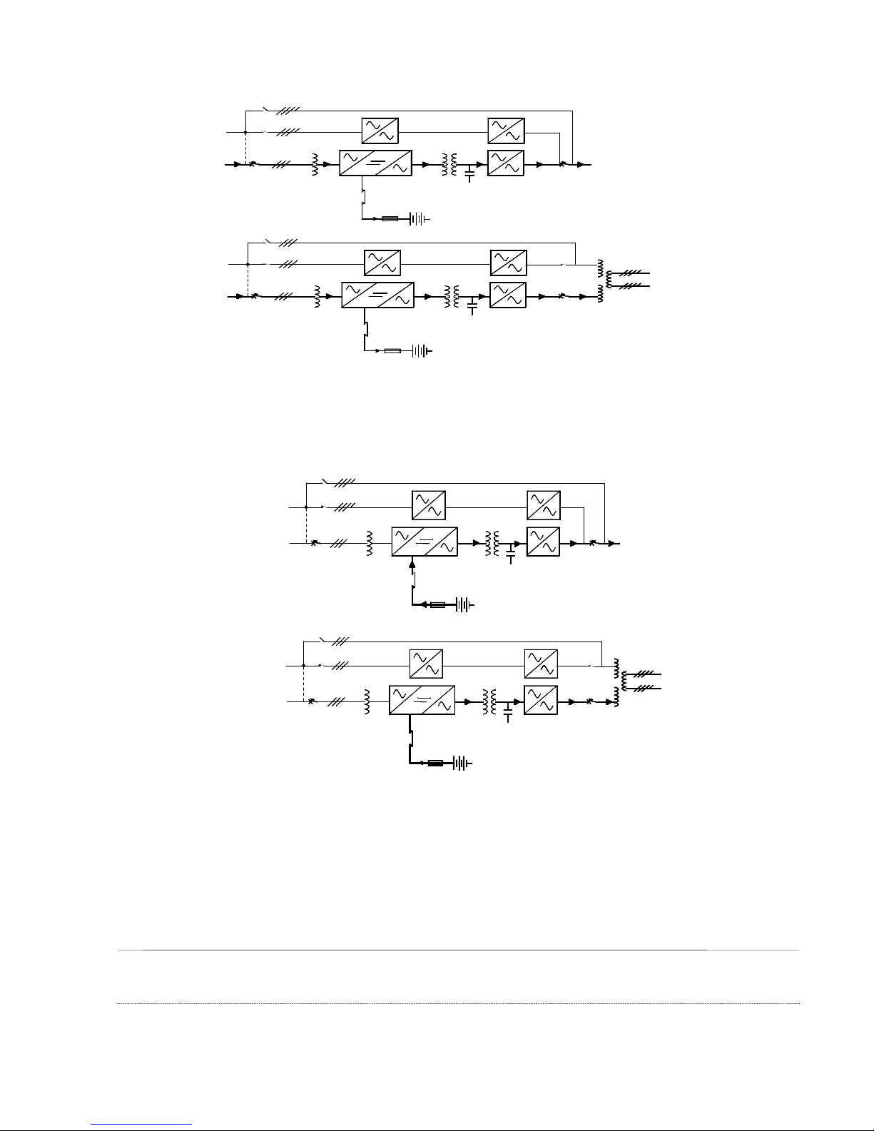
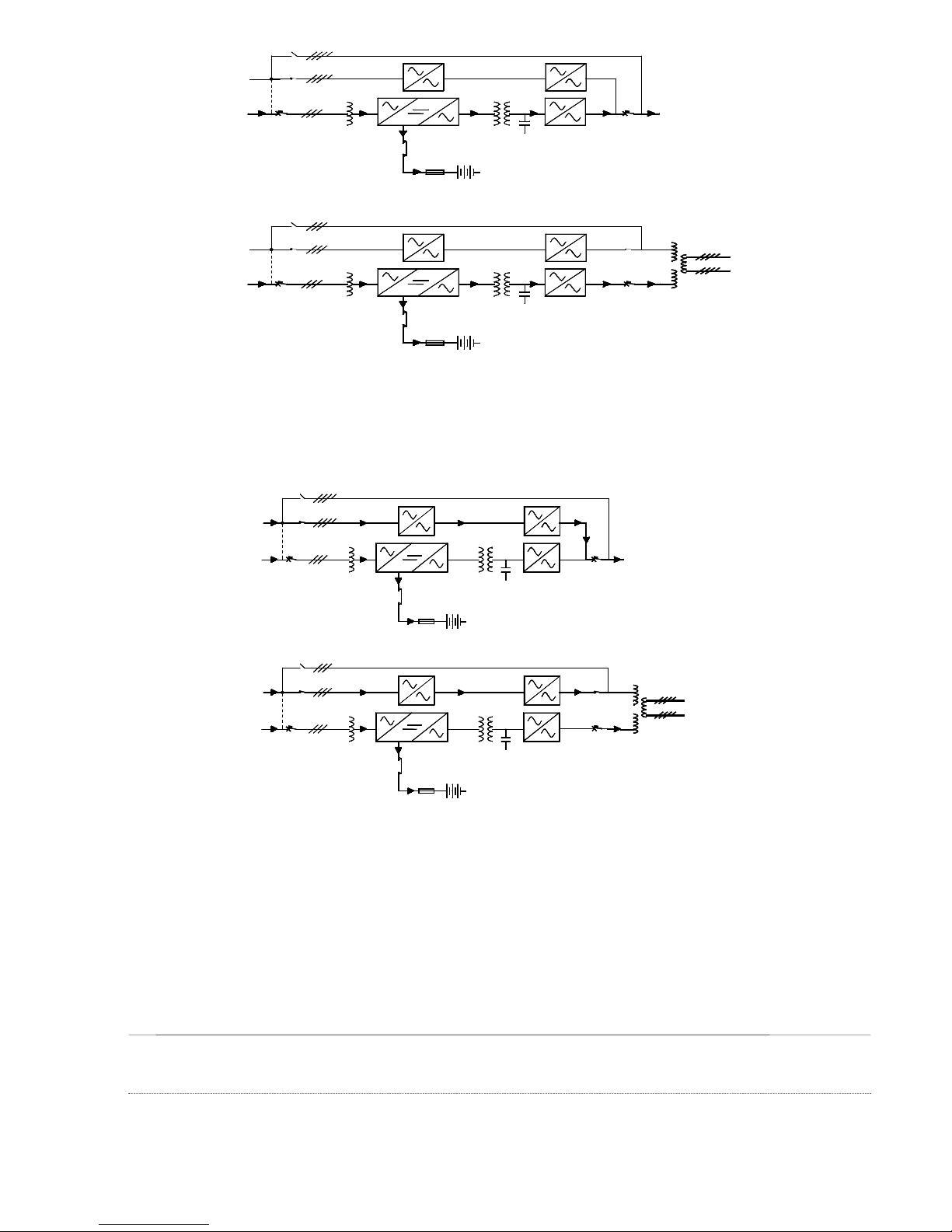
The block diagram, shows the main functional sub-assemblies of the EDP70 PLUS UPS. The AC three phase utility
supply is rectified to provide direct current, which maintains the battery in a fully charged state and also supplies the
inverter, which provides the three phase output via an electronic static switch.
Normally the supply of the reserve line is taken from the AC utility input, but special units, with a separate reserve input
supply, are available. This allows the inputs to be supplied from independent three phase sources.
Provided the reserve supply is within limits, the inverter will match the output frequency with the reserve supply
frequency. The inverter has its own internal crystal control to stabilize the output frequency if the reserve supply
frequency is out of limits. The electronic static switch switches the output from the inverter to the reserve supply, without
interruption, to meet any load current surges, or to supply the load if the battery is discharged during an AC utility supply
failure.
Maintenance and testing can be carried out on the EDP70 PLUS UPS without interrupting the output, by switching the
load from the reserve supply to the maintenance bypass circuit. This work should only be carried out by Chloride-trained
personnel.
p ge
10 --
MI00/10056 rev. 8 —05/2006
1.3 Block diagram
Figure 1 – lock diagrams – 24/36kVA
24 VA - STANDARD CONFIGURATION
Battery
Contactor
36 VA - STANDARD CONFIGURATION
Battery
Contactor
36 VA - 480V/208V CONFIGURATION
Battery
Contactor
S3
S3
IN THE ABSENCE OF A SEPARATE RESERVE
SUPPLY THE RESRVE IS DERIVED FROM THE
AC UTILITY INPUT WITH THE JUMPER
CONNECTED AS INDICATED
AC Supply
480V
Reserve Supply
480
208Y
S1
S2
IN THE ABSENCE OF A SEPARATE RESERVE
SUPPLY THE RESRVE IS DERIVED FROM THE
AC UTILITY INPUT WITH THE JUMPER
CONNECTED AS INDICATED
AC Supply
480
IN THE ABSENCE OF A SEPARATE RESERVE
SUPPLY THE RESRVE IS DERIVED FROM THE
AC UTILITY INPUT WITH THE JUMPER
CONNECTED AS INDICATED
Reserve Supply
208Y
S1
208Y
S2
S2
S3
S1
208Y/120V
AC Supply
Reserve Supply
290
2
240 Cells
(External)
1
208Y
250
3
4
5
S4
Maintenance By-pass
4
2
240 Cells
(External)
1
144 Cells
(Internal)
Maintenance By-pass
5
208Y
250
3
2
S4
Maintenance By-pass
3
1
208150
5
4
S4
MI00/10056 rev. 8 — 05/2006-- p ge
11
Figure 2 – lock diagram – 50/80kVA
The uninterruptible power system consists of the following:
1 - RECTIFIER/INVERTER S1 = Equipment ON/OFF switch
2 - BATTERY S2 = Equipment Reserve switch
3 - BACKFEED PROTECTION S3 = Equipment By-pass switch
4 - INVERTER STATIC S ITCH S4 = Equipment OUTPUT switch
5 - RESERVE STATIC S ITCH (INVERTER OUTPUT switch for 50/80kVA only)
S5 = RESERVE OUTPUT switch for 50/80kVA only
1.4 Functions
   
The rectifier/battery charger transforms the alternating current of the mains supply to direct voltage to maintain the
battery in a fully charged state and also supply the inverter.

The battery is an energy reserve that is used by the inverter and the load whenever the mains supply fails.

The inverter changes the direct voltage from the rectifier or from the battery into a three phase sinusoidal alternating
voltage for the external supply.
  
The function of the electronic static switch is to select one of the two sources of alternating voltage and to supply it to the
external load. The two sources of voltage supplied to the static switch are the output of the inverter and the reserve
supply. In normal working conditions, the static switch supplies the load from the inverter.

The switches permits maintenance and repair of the UPS, without interrupting the supply to the load.
3
Maintenance Bypass
IN THE ABSENCE OF A SEPARATE
RESERVE SUPPLY THE RESERVE IS
DERIVED FROM THE AC UTILITY
INPUT WITH THE JUMPER
CONNECTED AS INDICATED
AC Supply
240 Cells
(External)
Battery
Contactor
1
S1
480V
S2
Reserve
Supply
S3
2
4
480Y/277V
S4
5
208Y/120V
S5
p ge
12 --
MI00/10056 rev. 8 —05/2006
1.5 Operational modes
Figure 3 – Normal operation
During normal operation the load is supplied by the mains through the rectifier and inverter. The rectifier also supplies
the current for recharging and maintaining the battery in a fully charged state.
Figure 4 – Utility Supply failure
hen the utility supply voltage is absent or outside the allowed tolerances, the battery supplies the inverter. This will be
indicated on the UPS front panel display and the Remote Alarm Unit (if fitted). The standby time available depends both
on the capacity of the battery and on the size of load. It is possible to extend autonomy by reducing the output power by
disconnecting non-important loads. In all cases, the alphanumerical display shows the residual autonomy.
S3
AC Supply
S1
S2
Battery
Contactor
AC Supply
S1
S2
S3
Battery
Contactor
Maintenance By-pass
50/80kVA Ratings
S4
S5
208Y/120V
480Y/277V
LOAD
Maintenance By-pass
S4
24/36kVA Ratings
LOAD
Battery
Contactor
Battery
Contactor
LOAD
AC Supply
Reserve Supply
S1
S2
S3
AC Supply
Reserve Supply
S1
S2
S3
50/80kVA Ratings
Maintenance By-pass
208Y/120V
480Y/277V
S5
S4
24/36kVA Ratings
Maintenance By-pass
LOAD
S4
MI00/10056 rev. 8 — 05/2006-- p ge
13
Figure 5 – Re-establishing the Utility Supply
hen the utility supply returns within acceptable limits, the UPS returns automatically to normal operation mode as
previously described. The rectifier now starts to recharge the battery. However, until recharge has been completed, any
further mains failure will result in reduced standby times.
Figure 6 – Transferring the Load onto the Reserve Supply
Transfer onto the reserve line is caused by two conditions:
) inverter stop
b) overload
In both instances the load is transferred onto the reserve without interruption. If the overload is temporary, the system will
re-transfer from reserve to inverter as soon as the it ceases. This allows for the initial start-up of loads with high or
excessive switch-on currents.
S1
AC Supply
Reserve Supply
S2
S3
Battery
Contactor
AC Supply
Reserve Supply
S1
S2
S3
Battery
Contactor
Maintenance By-pass
S4
S5
50/80 VA Ratings
208Y/120V
480Y/277V
Maintenance By-pass
S4
24/36 VA Ratings
S1
AC Supply
Reserve Supply
S2
S3
Battery
Contactor
AC Supply
Reserve Supply
S1
S2
S3
Battery
Contactor
Maintenance By-pass
50/80 VA Ratings
208Y/120V
480Y/277V
S5
S4
Maintenance By-pass
24/36 VA Ratings
S4
p ge
14 --
MI00/10056 rev. 8 —05/2006
2.0 SAFETY
Read all instructions carefully before installing or operating the equipment.
2.1 eneral safety
The procedure described in these instructions is intended for use by persons experienced in the operation of
Uninterruptible Power Systems and ancillary equipment.
Persons unfamiliar with this type of equipment should seek guidance from experienced personnel.
The EDP70 PLUS UPS is designed to be operated in accordance with existing safe operating procedures.
These instructions are not intended to replace existing safety practices.
If there are any questions regarding the safe operation of the system, contact a Chloride service representative.
This equipment is designed and built for safe operation when used to supply its rated load, providing it is installed as
specified by qualified, licensed and competent electricians.
Electrical energy can be supplied by the equipment and the battery.
2.2 Symbols
The following symbols appear in this book and in the unit:
W rning -
Hazardous voltages are present. If the instructions are not heeded, there is a risk of
electrical shock and danger to personal safety.
DIRECT CURRENT SUPPLY
ALTERNATING CURRENT SUPPLY
ON position of the switches
OFF position of the switches
Inverter St rt Up For explanation see Para. 6.2. of this manual
Inverter Shutdown For explanation see Para. 6.2. of this manual
Audible Al rm C ncel Switch For explanation see Para. 6.2. of this manual
MI00/10056 rev. 8 — 05/2006-- p ge
15
P ge Right Control For explanation see Para. 6.2. of this manual
Record Up For explanation see Para. 6.2. of this manual
Record Down For explanation see Para. 6.2. of this manual
2.3 Electrical precautions
Never handle a component or assembly without first confirming that no voltage is applied or present. Remove only those
protective covers that are essential to perform the repairs or adjustment currently required, and replace them as soon as
possible.
. Use only insulated tools.
. Place a rubber insulating mat in front of all equipment doors.
. Keep all door closed and locked at all times during normal operation.
2.4 Battery precautions
Always isolate the load before connecting or disconnecting the batteries or battery cells.
Ensure that batteries are fully isolated by disconnecting the battery connectors, opening circuit breakers, or both.
Remove all jewellery from hands, wrists and neck before working on batteries or battery cells.
Before leaning over batteries, remove any metal object that could fall out of pockets.
Do not place tools or other conductive objects on the batteries.
2.5 Battery safety equipment
hen working on or handling batteries, ensure that the following items are worn:
. Eye goggles
. Rubber gloves
. Rubber apron
. Rubber boots
hen batteries are being moved or worked on, ensure the following items are available in the immediate vicinity:
. An eye bath, eyewash station or equivalent
. A clean water source to wash spilled acids
. Absorbent materials to soak up spilled acids
. Disposal for contaminated materials.
p ge
16 --
MI00/10056 rev. 8 —05/2006
3.0 STORAGE
If the EDP70 PLUS UPS cannot be installed within sixty days of delivery, there is a danger of the integral battery
becoming discharged thereby sustaining permanent damage and affecting the standby period available and battery life.
The date the battery was last recharged and the date the battery is due for its next recharge are both stamped on the
packaging accompanying the unit. If you intend to store the unit, please refer to the recharge date.
hen the EDP70 PLUS is due to be recharged, refer to the Installation instructions and connect the EDP70 PLUS UPS
to a temporary AC supply. The battery MUST be recharged for at least 24 hours every 3 months.
4.0 INSTALLATION
4.1 Mechanical characteristics
- Ambient temperature 18°F[-10°C] to 104°F [+40°C ]
- Relative Humidity (w/out condensing @ 68°F[20°C]) < 90%
- Max altitude (w/out derating) 3300 feet [1000 m] above sea-level
- Protection degree (panel fitted)
- Input cables bottom
- Air inlet bottom
- Air outlet rear
UPS model
Description u.m. 24 36 50 80
Size width
depth
height
In
[mm]
28-.5 [700]
28.7 [730]
56 [1420]
27.5 [700]
28.7 [730]
56 [1420]
35.4 [900]
28.7 [730]
63 [1600]
35.4 [900]
28.7 [730]
63 [1600]
Total
eight
(UPS +
Battery)
w/out cells
25 Ah cells
30 Ah cells
35 Ah cells
Lbs
[kg]
880 [400]
1342 [610]
1456 [662]
1526 [694]
1300 [590]
n.a.
n.a.
n.a.
1342 [610]
n.a.
n.a.
n.a.
1800 [818]
n.a.
n.a.
n.a.
Floor Area In
2
[m
2
] 789 [0.511] 789 [0.511] 1019 [0.657] 1019 [0.657]
Floor
Loading
(UPS +
Battery)
w/out cells
25 Ah cells
30 Ah cells
35 Ah cells
Lbs/in
2
[kg/m
2
]
1.12 [782]
1.70 [1194]
1.85 [1296]
1.93 [1358]
1.65 [1155]
n.a.
n.a.
n.a.
1.32 [930]
n.a.
n.a.
n.a.
1.77 [1245]
n.a.
n.a.
n.a.
Air-Flow cfm
[mc/h]
235
[400]
647
[1100]
1165
[1980]
1553
[2640]
Acoustic Noise
100% Linear Load dBA 52 55 55 62
Notes: 1) n.a. = not applicable
2) Longer autonomies, and battery for EDP above 20 kVA are available with external
battery cubicles.
MI00/10056 rev. 8 — 05/2006-- p ge
17
Figure 7 – 24 Footprint nd c binet dimensions
150
(5.9)
(25.39)
30,0
600,0
(1.18)
645,0
260 (10.24) X 66 (2.6)
(23.62)
(ø0,31)
NR 4 X ø8
CABLE ENTRY
58,0 (2.28)
(28.5)725,0
1422,0 (56)
ALL MEASUREMENTS ARE IN
MILLIMETERS (AND INCHES)
700,0 (27.56)
(2.64)
67,0
63,0 (2.48)
SPACE REQUIRED
BY THE WHEEL
WHEN ROTATING
200
(7.87)
730,0 (28.7)
(26.77)
680,0
p ge
18 --
MI00/10056 rev. 8 —05/2006
Figure 8 – 36 Footprint nd c binet dimensions
50,0
200
(7.87)
SPACE REQUIRED
BY THE WHEEL
WHEN ROTATING
600,0
CABLE ENTRY
500 (19.68) X 110 (4.33)
(25.39)
(1.18)
645,0
30,0
(23.62)
500 (19.7)
530 (20.9)
150
(5.9)
700,0
NR 4 X
(
ø
0
,
3
1
)
ø
8
125,0
(4.92)
(27.5)
1422,0 (56)
ALL MEASUREMENTS ARE IN
MILLIMETERS (AND INCHES)
700,0 (27.56)
(1.97)
(3.46)
88,0
730,0 (28.7)
(26.77)
680,0
MI00/10056 rev. 8 — 05/2006-- p ge
19
Figure 9 – 50/80 Footprint nd c binet dimensions
50,0
SPACE REQUIRED
BY THE WHEEL
WHEN ROTATING
800,0
700 (27.56) X 110 (4.33)
CABLE ENTRY
(25.39)
(1.18)
645,0
30,0
(31.5)
200
(7.87)
150
(5.9)
100,0
NR 4 X
ø
8
(
ø
0
,
3
1
)
(3.94)
1600 (63.0)
ALL MEASUREMENTS ARE IN
MILLIMETERS (AND INCHES)
900,0 (35.4)
(1.97)
(2.68)
68,0
730,0 (28.7)
p ge
20 --
MI00/10056 rev. 8 —05/2006
Figure 10 — “A” B ttery C binet Dr wing for 24/36kVA R tings

Other manuals for EDP70

1

This manual suits for next models

1

Other Chloride UPS manuals

Chloride SE041XAT Operator's manual

Chloride

Chloride SE041XAT Operator's manual

Chloride Cool Power 600 User manual

Chloride

Chloride Cool Power 600 User manual

Chloride Desk POWER 300 User manual

Chloride

Chloride Desk POWER 300 User manual

Chloride SYNTHESIS User manual

Chloride

Chloride SYNTHESIS User manual

Chloride Power Protection Active 700 User manual

Chloride

Chloride Power Protection Active 700 User manual

Chloride LP061XHR Operator's manual

Chloride

Chloride LP061XHR Operator's manual

Chloride EDP70 Instruction Manual

Chloride

Chloride EDP70 Instruction Manual

Chloride Desk POWER 300 User manual

Chloride

Chloride Desk POWER 300 User manual

Chloride Desk Power Plus 1000 User manual

Chloride

Chloride Desk Power Plus 1000 User manual

Chloride Power Protection Active 700 User manual

Chloride

Chloride Power Protection Active 700 User manual

Chloride CP3000 Series User manual

Chloride

Chloride CP3000 Series User manual

Chloride VA 1000 Operator's manual

Chloride

Chloride VA 1000 Operator's manual

Chloride CP3150 Series User manual

Chloride

Chloride CP3150 Series User manual

Chloride ACTIVE A0K7XAU User manual

Chloride

Chloride ACTIVE A0K7XAU User manual

Chloride Power Protection Active 700 User manual

Chloride

Chloride Power Protection Active 700 User manual

Chloride Power Star User manual

Chloride

Chloride Power Star User manual

Popular UPS manuals by other brands

Trust Wireless Tablet Series user manual

Trust

Trust Wireless Tablet Series user manual

Eaton 9E Installation and operation manual

Eaton

Eaton 9E Installation and operation manual

Salicru 750 VA user manual

Salicru

Salicru 750 VA user manual

Tescom NEOLINE 1000 user manual

Tescom

Tescom NEOLINE 1000 user manual

Emerson Liebert GXT4-5000RT230 user manual

Emerson

Emerson Liebert GXT4-5000RT230 user manual

Belkin F6C1000EITW-RK user manual

Belkin

Belkin F6C1000EITW-RK user manual

CyberPower OR600ERM1U user manual

CyberPower

CyberPower OR600ERM1U user manual

Huawei UPS5000-H-1200K-NT user manual

Huawei

Huawei UPS5000-H-1200K-NT user manual

Always “On” UPS Limousin II user manual

Always “On” UPS

Always “On” UPS Limousin II user manual

socomec ITYS Installation and operating manual

socomec

socomec ITYS Installation and operating manual

CyberPower BR1000ELCD user manual

CyberPower

CyberPower BR1000ELCD user manual

Toshiba 1500 Series Operation manual

Toshiba

Toshiba 1500 Series Operation manual

Powerware Prestige series 9 user guide

Powerware

Powerware Prestige series 9 user guide

Huawei UPS5000-A-400 kVA user manual

Huawei

Huawei UPS5000-A-400 kVA user manual

Forza HT-752LCD-C manual

Forza

Forza HT-752LCD-C manual

Maruson TAC-HV1K user manual

Maruson

Maruson TAC-HV1K user manual

AEC IST5 Series Service manual

AEC

AEC IST5 Series Service manual

Tecnoware EVO DSP PLUS 800 PF 0.9 user manual

Tecnoware

Tecnoware EVO DSP PLUS 800 PF 0.9 user manual

manuals.online logo
manuals.online logoBrands
  • About & Mission
  • Contact us
  • Privacy Policy
  • Terms and Conditions

Copyright 2025 Manuals.Online. All Rights Reserved.