Chocolate World Scirocco User manual
Lange Elzenstraat 123 • 2018 Antwerpen • Belgium • Tel. +32 (0)3 216 44 27
HOT CHOCOLATE DISPENSER
OPERATOR’S MANUAL
CARNET D’INSTRUCTIONS
MANUAL DE INSTRUCCIONES

3
4
SCIROCCO UL
ENGLISH
1 TECHNICAL CHARACTERISTICS
The manufacturer reserves the right to make
changes without any prior notification.
2 INTRODUCTION
Read this instruction manual carefully to know the
specifications of the dispenser. As all mechanical
products, this unit requires cleaning and
maintenance. Its working order can be
compromised by possible errors made by the
operator during disassembly and cleaning. For
this reason it is important that the staff in charge
of the dispenser is qualified to carry out the day to
day operations, which are dismantling, cleaning,
sterilisation and reassembly.
3 INSTALLATION
1Remove the dispenser from the packaging.
(This should be kept for any future requirement)
2Check the dispenser has not been damaged
during transport. The forwarding agent must be
notified immediately of any claim.
3Install the dispenser on a counter top that will
support its weight, even with a full load.
4Before connecting the dispenser electrically
check that the voltage (in the network) is as
shown on the data plate. Plug the unit into a
grounded, protected single phase electrical
supply according to the applicable electrical
codes and the specifications of your machine. If
you want to make a fixed connection to the
network, connect the cord to a bipolar wall
breaker with a contact gap of at least 3mm. not
use extension cords to co nnect the unit
electrically.
5The dispenser does not leave the factory
presanitized and sanitized. Prior to use it must be
disassembled, cleaned and sanitized according
to the instructions in chapter 5.3 CLEANING.
4 TO OPERATE SAFELY
1Read the instruction booklet before using the
dispenser.
2Use the dispenser only if it is grounded
correctly.
3Do not use extension cords to connect the
dispenser electrically.
4Do not operate the dispenser if it is not
closed and blocked with screws.
5Do not place fingers or objects in the cooling
fissures and faucet outlet panels louvers.
6Do not remove the container when the unit is
in operation.
7This unit is not meant to be used outside.
8This unit is not to be installed in areas
subject to water-spouts.
9Do not use water-jets to clean the unit.
10 This unit can work in a room temperature
Scirocco
Transparent removable bowls n 1
Capacity of each bowl, approx. l 5
Dimensions:
width cm 24
depth cm 32
height cm 49
Net weight, approx. kg 7
Gross weight, approx. kg 8
Adjustable thermostats n 2
Noise level lower than 70 dB (A)
IMPORTANT
Electric specifications: read the informa-
tion on the data plate of each single dispen-
ser, situated on the underside. The serial
number of the units is preceded by #
ATTENTION
Ensure that the unit is grounded correctly;
if not it may cause electric shock to per-
sons or damage the dispenser.
4
5
range between +5° and +50°C.
5 OPERATING PROCEDURES
1Clean and sanitized the dispenser prior to
use following the instructions in chapter 5.3
CLEANING.
2Fill the bowl with the product, prepared
according to the instructions of the manufacturer.
3Install the cover above the container making
sure that it is placed correctly.
4Set the control switch (see charter 5.1.
COMMAND DESCRIPTIONS)
5The dispenser should always operate with
the cover installed in order to prevent possible
contamination of the product.
6The dispenser must run uninterruptedly;
heating will stop automatically when the product
is ready for dispensing. The mixing device will
continue to operate.
7The dispenser is supplied with a container
with a closed removable bottom to facilitate
cleaning and sterilisation.
5. 1 DESCRIPTION OF CONTROLS
The dispenser is equipped with a general switch
whose functions are:
The dispenser is equipped with a thermostat, on
the right side, to adjust the temperature of the
product.
Comment: the dispenser is also equipped with a
second thermostat on the underside to regulate
the temperature of the hot plate. This is calibrated
in the factory. If necessary, it is possible to act on
the thermostat reducing the temperature of the
hot plate to prevent possible burns. This will
lengthen the heating time of the product and it will
never be possible to obtain a product at a higher
temperature to that set for the hot plate.
5. 2 OPERATION HELPFUL HINTS
hot chocolate: preparation following the
traditional artisan method, mix the cocoa with milk
or water well in a pan before pouring it into the
bowl. Follow the instructions of the manufacturer
if using packaged instantaneous products. It is
possible to mix these directly in the container.
Activate the dispenser turning the switch to
position 1. Turn the thermostat knob to 90°C to
obtain the cooking temperature of the product.
When the hot chocolate is ready lower the
temperature to the value required for dispensing
turning the thermostat knob.
5. 3 CLEANING AND SANITIZING
PROCEDURES
Cleaning and sanitizing are essential to maintain
perfect taste and maximum efficiency from your
dispenser. The procedures described below are
general and can vary due to the sanitary
regulations of the local health authorized.
The product must be taken out of the dispenser
before it is disassembled for cleaning.
ATTENTION
Do not remove the container until the hot
plate is cold.
ATTENTION
Do not remove the container from the
dispenser when it contains hot products.
IMPORTANT
Place the unit on an horizontal surface.
ATTENTION
In case of damages, the power cord must
be replaced by qualified personnel only in
order to prevent any shock hazard.
Position 0 : power is turned off
Position I : mixer and heating device in
working order
IMPORTANT
Before switching off the dispenser comple-
tely (switch at position 0), bring the thermo-
stat to the lowest temperature and wait for
the product to cool down. This stops the
product (if not agitated) from sticking to the
hot plate
5
6
SCIROCCO UL
ENGLISH
5. 3. 1 DISASSEMBLY
1Empty the bowl and remove the lid
2Remove the mixer from the central shaft
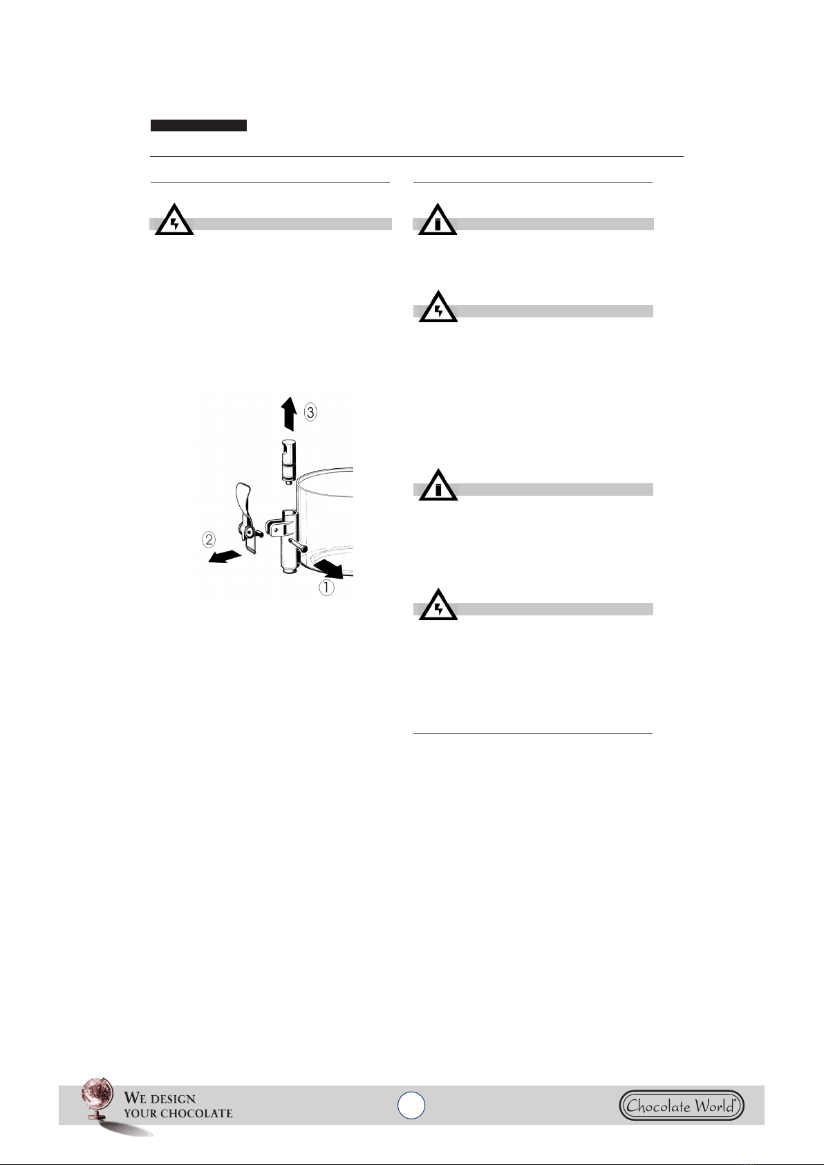
3Dismantle the faucet following the sequence
shown (see fig. 1)
figure 1
4Remove the container, lifting it upwards.
5Remove the drip-tray and empty it.
5. 3. 2 CLEANING
1Prepare approx. four litres (2 gallons) of hot
water (45-60° C) and specific detergent in a bowl
according to the instructions of the manufacturer;
a solution, which is too concentrated, may cause
damage to the parts to be washed, one that is
too diluted will not clean adequately. Do not use
abrasive detergents.
2Use a suitable brush and carefully clean all
the parts in contact with the drink
3Rinse all the washed parts in running water.
5. 3. 3 SANITIZING
The dispenser must be sanitized prior to starting
the machine. Do not allow the unit to sit for
extended periods of the time after sanitization
1Before starting the procedure described
below wash hands with an anti-bacterial soap.
2Prepare at least. four litres of hot water (45-
60°C) and sterilising product legally approved in
your Country, following the instructions of the
manufacturer. If there is no specific sterilising
product prepare a solution of water and bleach in
ATTENTION
Before proceeding to disassemble any com-
ponent always disconnect the unit from the
electricity removing the plug or switching
off the 2 pole wall breaker.
IMPORTANT
Before cleaning disconnect the dispenser
from the electricity taking out the plug or
turning off the outside switch on the wall.
ATTENTION
Do not wash any component of the
machine in the dishwasher.
IMPORTANT
Use detergents compatible with the plastic
parts to avoid damaging the dispenser.
ATTENTION
Do not use excessive amounts of water
near the electric components of the dispen-
ser when washing it as this can cause
electric shock or damage the dispenser.
6
7
the following ratio: 1 tbsp: 2 litres of water.
3Immerse all the parts to be sterilised in the
solution for time indicated by the manufacturer.
4Allow the sterilised parts to air dry on a clean
surface.
5Use non-abrasive cloths to dry the external
parts.
5. 3. 4 ASSEMBLY
1Put the drip-tray and grill in place
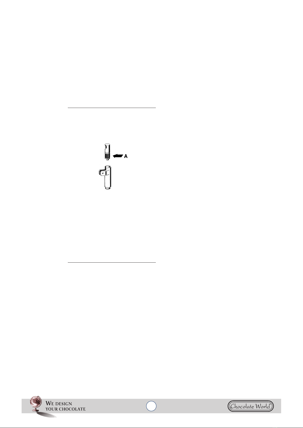
2Lubricate the faucet piston (in the area A
shown in fig. 2) using food grade approved
lubricant.
figure 2
3Reassemble the faucet assembly on the
container in the opposite way to which it was
dismantled (see fig. 1).
4Install the container putting the central shaft
in place.
5Insert the mixer in the central shaft
6Position the cover on the container.
6 MAINTENANCE
1Daily: check the dispenser for any loss of
product from the gaskets. If there is, first check
the dispenser is assembled correctly making
sure that the gaskets need no lubricating and
they are not faulty or worn. In this case they must
be replaced with original parts.
2To avoid damage to the dispenser the plastic
parts must be lubricated only with the grease
supplied by the manufacturer or other grease
compatible with polycarbonate.

7
SCIROCCO UL
8
ENGLISH
TROUBLESHOOTING
PROBLEM CAUSE SOLUTION
Mixer doesn't turn Drive shaft coupling not cor-
rect Check that it's in the cor-
rect operating position
Drive shaft coupling broken Replace mixer and/or drive
shaft
Gear motor not working See “Gear motor doesn't
turn”
Electrical wires disconnected
or interrupted Connect or replace
electrical wires
Product too dense Dilute the product
Gear motor doesn't turn Motor overheated: “Thermal
Protection” tripped Check the voltage of the
outlet. Check the
ventilation (fins on the side
panels obstructed or lower
part of the distributor
obstructed). Check the
viscosity of the product
Stator winding burned out or
interrupted Replace the motor
Rotor shifted Check the alignment of the
rotor bearings
Gears in the reducer box
damaged or worn Replace the motor
Beverage leaks from the
container Container gasket seal broken
or worn Replace gasket seal
Tap piston o-ring broken or
worn Replace the piston o-ring
Tap piston not in closed posi-
tion Check the tap lever or
spring and replace the
worn part
8
9
Heating element not hot Heating element burned out Replace the heati ng
element
The maximum temperature
thermostat (located under the
distributor) is set too low
Regolarlo alla temperatura
opportuna
Thermal fuse burned out Adjust it to a suitable
temperature
Thermal fuse burned out Thermal fuse defective Replace with a good one
Maximum temperature
thermostat doesn't intervene Replace maximum
temperature thermostat
I'm not getting a suffi-
ciently dense product The temperature of the
service thermostat (located on
the side of the distributor) is
set too low
Adjust it to a suitable
temperature
The maximum temperature
thermostat (located under the
distributor) is set too low
Adjust it to a suitable
temperature
Product excessively diluted Increase the concentration
of the product
I'm not getting a suffi-
ciently hot product The temperature of the
service thermostat (located on
the side of the distributor) is
set too low
Adjust it to a suitable
temperature
The bottom of the tub is not
touching the heating element Position the tub on the
heating element correctly
PROBLEM CAUSE SOLUTION
21
SCIROCCO UL
22
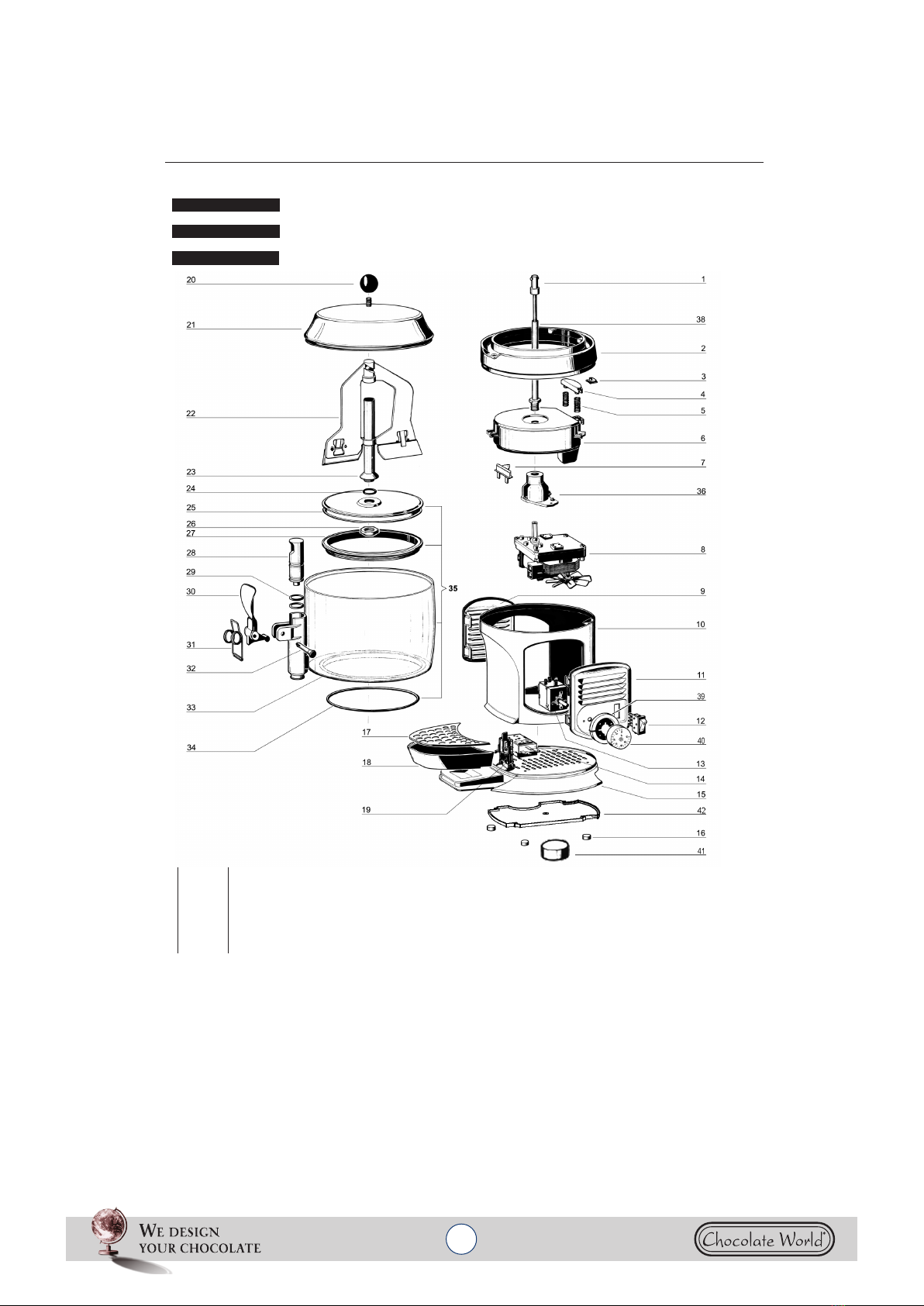
SPARE PARTS LIST
LISTE DES PIECES DE RECHANGE
DESCRIPCION PIEZAS DE REPUESTO
1 33800-09800 Driving shaft Arbre de trainement Eje transmisión
2 22800-26408 Heating plate holder Support plaque chauffante Soporte para plancha calentadora
2 22800-26427 Heating plate holder -“gold” Support plaque chauffante -“or” Soporte para plancha calentadora -”oro”
3 10554-44000 M4 Clip Clip M4 Clip M4
4 22800-26415 Thermostat bulb holder Support boule du thermostat Guia-sensor termóstato
5 22800-26420 Spring for bulb holder Ressort pour support boule Muelle para guia-sensor termóstato
6 33800-09701 Heating plate 115V 60Hz Plaque chauffante Plancha calentadora
7 22800-26426 Limit switch Thermolimiteur Fusible de seguridad
ENGLISH
FRANCAIS
ES P AÑ OL
2453_29 V 0.6 06G10
22
23
8 22092-00014 Complete gear motor 115V 60Hz Motoréducteur complet Motorreductor completo
9 22800-26478 Side panel Panneau latéral Panel lateral
9 22800-26433 Side panel -“gold” Panneau latéral -“or” Panel lateral -”oro”
9 22800-26438 Side panel -”silver” Panneau latéral -”argent” Panel lateral -”plata”
10 22800-26476 Machine body Carrosserie Cuerpo maquina
10 22800-26431 Machine body -“gold” Carrosserie -“or” Cuerpo maquina -”oro”
10 22800-26436 Machine body -”silver” Carrosserie -”argent” Cuerpo maquina -”plata”
11 22800-26477 Side panel for controls Panneau latéral pour contrôles Panel lateral completo de mandos
11 22800-26432 Side panel for controls -“gold” Panneau latéral pour contrôles -“or” Panel lateral completo de mandos -”oro”
11 22800-26437 Side panel for controls -”silver” Panneau latéral pour contrôles -”argent” Panel lateral completo de mandos -”plata”
12 22800-24301 Switch Interrupteur Interruptor
13 22037-00000 0-90°C thermostat Thermostat 0-90°C Termóstato 0-90°C
14 22037-00001 0-120°C thermostat Thermostat 0-120°C Termóstato 0-120°C
15 22800-26475 Base Base Base
15 22800-26430 Base -“gold” Base -“or” Base -”oro”
15 22800-26435 Base -”silver” Base -”argent” Base -”plata”
16 22800-26417 Rubber leg Petit pied Pie de goma
17 22800-26406 Drip tray cover Couvercle tiroir égouttoir Rejilla cajón recoge-gotas
17 22800-26428 Drip tray cover -“gold” Couvercle tiroir égouttoir“or” Rejilla cajón recoge-gotas”oro”
18 22800-26464 Drip tray Tiroir égouttoir Bandeja goteo
18 22800-26434 Drip tray -“gold” Tiroir égouttoir -“or” Bandeja goteo -”oro”
18 22800-26439 Drip tray -”silver” Tiroir égouttoir -”argent” Bandeja goteo -”plata”
19 22800-05500 Cable clamp Borne Pasacable
20 22800-26416 Cover knob Pommeau du couvercle Pomo para tapa
21 22800-26409 Bowl cover Couvercle du réservoir Tapa contenedor
21 22800-26429 Bowl cover -“gold” Couvercle du réservoir -“or” Tapa contenedor -”oro”
22 22800-26414 Mixer Mélangeur Mezclador
23 22800-26412 Bowl shaft Arbre du réservoir Arbol del contenedor
24 22800-26419 Bowl shaft O-ring OR de l’arbre du réservoir OR para àrbol central
25 22800-26407 Bowl bottom plate Fond du réservoir Fondo del contenedor
26 10533-03005 Central shaft nut Ecru arbre du réservoir Dado para eje central
27 22800-26410 Bowl gasket Joint du réservoir Junta contenedor
28 22800-14801 Faucet piston Piston du robinet Pistón del grifo
29 22800-15100 Faucet piston O-ring Joint OR du robinet Junta OR del grifo
30 22700-01860 Green faucet handle Levier de débit vert Palanca grifo
30 22700-01801 Black Faucet handle Levier de débit noir Palanca grifo
31 22800-26424 Faucet spring Ressort du robinet Muelle del grifo
32 22800-22161 Green faucet handle pin Pivot vert pour levier de débit Pivote verde de la palanca
32 22800-22160 Black faucet handle pin Pivot noir pour levier de débit Pivote negro de la palanca grifo
33 22800-26405 Bowl Réservoir Contenedor
34 22800-26418 Bowl O-ring OR du réservoir OR del contenedor
35 33800-09901 Bowl assembly Réservoir complet avec fond Contenedor completo
36 22001-00001 Gear motor flange Bride pour motoréducteur Brida para motorreductor
38 22800-26413 Central shaft Arbre central Eje central
39 22800-26466 Tap ring Mancon Pomo para termostato
40 22800-26456 Thermostat knob 32-194F Pommeau du thermostat 32-194F Pomo para termostato 32-194F
41 22800-26457 Thermostat knob 32-248 F Pommeau du thermostat 32-248 F Pomo para termostato 32-248 F
42 22800-26455 Base protection
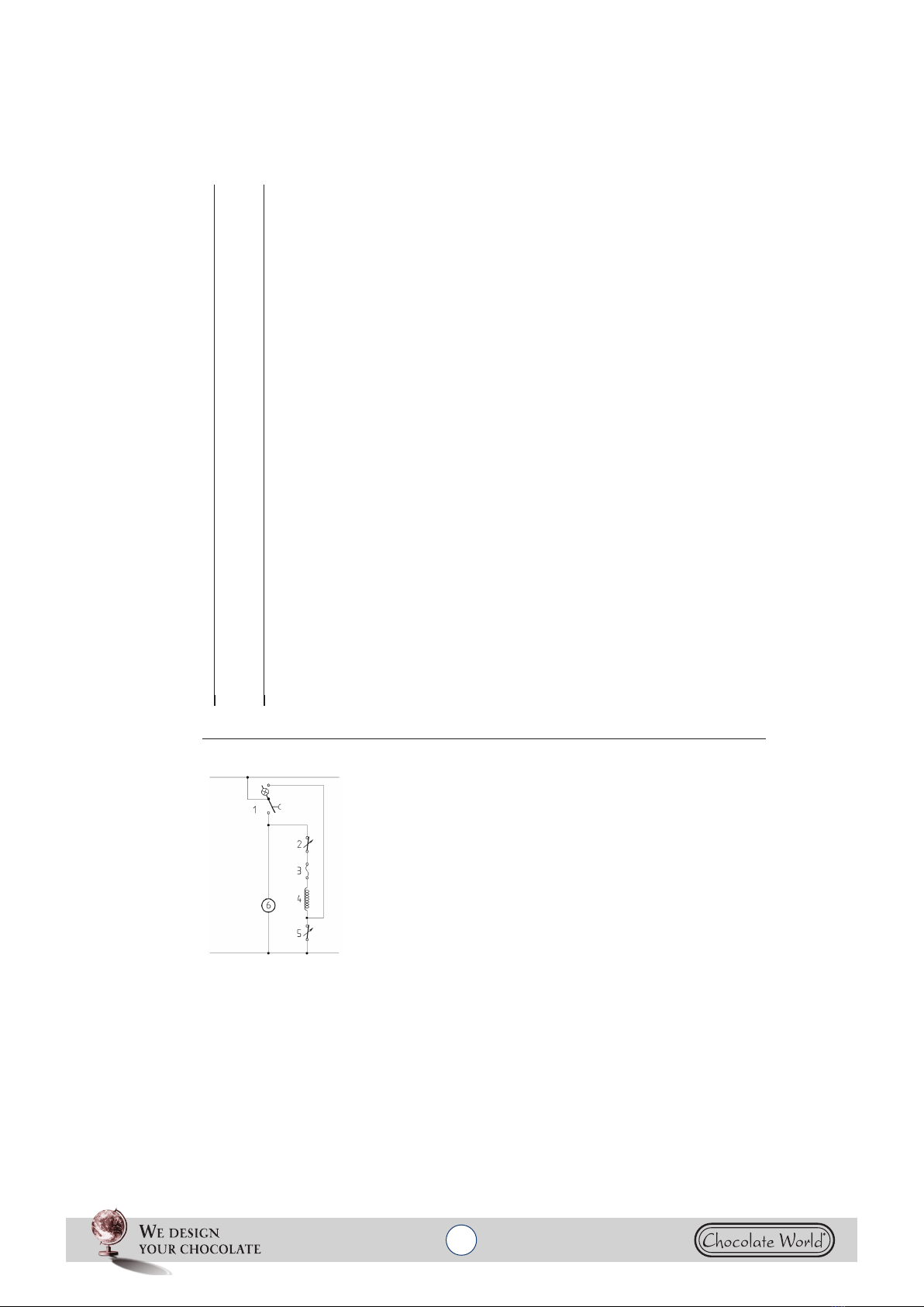
SCHEMA ELETTRICO / WIRING DIAGRAM / SCHEMA ELECTRIQUE / SCHALTSCHEMA / ESQUEMA ELECTRICO
1 Interruttore Switch Interrupteur Dreiwegeschalter Interruptor
2 Termostato 0-120°C 0-120°C Thermostat Thermostat 0-120°C Thermostat 0-120°C Termóstato 0-120°C
3 Termolimitatore 152°C Limit switch 152°C Thermolimiteur 152°C Sicherung 152°C Fusibile de seguridad
4 Resistenza Resistance Resistance Heizung Resistencia
5 Termostato 0-90°C 0-90°C Thermostat Thermostat 0-90°C Thermostat 0-90°C Termóstato 0-90°C
6 Motoriduttore agitatore Gear motor Motoréducteur Motoruntersetzung Motoreductor
This manual suits for next models
2
Table of contents


