Hydro systems EvoRinse User manual

Installation and Operation Manual
HYD90098598 Rev A
EvoRinse

2
Contents
1 Specification
Description
Product Features
Specification
Intended Use
Product Diagram
Kit Contents
2 Installation
Site Survey & Installation Requirements
Installation Diagram
Mechanical Installation
Wall mounting
Rinse discharge hose connection
Rinse aid tube connection (product option)
Water connection
Electrical Installation
Electrical connections
Mains power wiring
3 Troubleshooting
Dead Unit
4 Maintenance
Maintenance
Every Maintenance Visit
Spray Nozzle Replacement
5 Spare Parts
6 Decommissioning & Disposal
7 Safety
8 EC Declaration of Conformity
9 WEEE

3
1.3 Specification
Product Dimensions (unboxed)
Size 254mm (W) x 366mm (L) x 234mm (D)
Weight 2.3 Kg
Product Dimensions (boxed)
Size 370mm (W) x 425mm (L) x 305mm (D)
Weight 3.4 Kg
Electrical
Input voltage / Frequency / Current 100 to 240 VAC / 50/60 Hz. / 1.5 A (Max.)
Power 12W (Max)
Electrical Class Class II
1. Specifications
Installation Environment
Temperature 10°C to 50°C (max.)
Humidity 95% relative humidity (max.)
Indoor Installation Indoor use only. Must not be installed outdoors
Performance
Detergent dissolution rate Min-max
Water Inlet Connection
Water temperature 5°C to 60°C (max.)
Pressure 0.2MPa (2 bar) - 0.6MPa (6 bar)
Inbuilt backflow prevention - EN1717 DB - Category 4 chemicals
1.2 Product Features
Bottle lockout feature to prevent non-approved chemicals
being used in the product.
1.1 Description
The EvoRinse is a rinse powder / solid rinse aid dissolver for
use with EvoWash warewash machines.
1.4 Intended Use
• The EvoRinse is intended for use in industrial applications
and is not suitable for domestic use.
• The product must only be used for rinsing in dish and
warewash applications. The manufacturer waives any
responsibility arisen from incorrect usage or transportation.

x 4 x 4 x 4
2
1
x 2
4
KEY:
1. Switch Lever
2. Keyway (optional)
3. Fixing Points (x4)
4. Water Inlet
5. Water Filter
6. Mesh Screen
7. Water Spray Nozzle
1
2
3
4
5
6
7
1
2
3
4
5
6
7
1
2
1
2
3
4
5
6
7
3
4
5
1.6 Kit Contents
1.5 Product Diagram
6
7

5
2. Installation
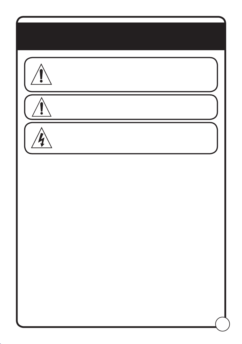
CAUTION Before an installation takes place it is
advisable to complete a site survey to ensure
the EvoRinse can be installed in a position that
meets all the requirements below.
CAUTION Do not install unit in an ATEX environment
WARNING Electrical installation should be completed
by a qualified electrician. All local and
national electrical regulations are to be
observed.
2.1 Site Survey & Installation Requirements
• Unit is to be installed by a trained technician; all local and
national water regulations are to be observed.
• Unit must be installed indoors, in an area that does not
suffer excess temperature changes, direct sunlight, frost or
precipitation of any kind.
• The area must be free of high levels of EMC disturbance.
• Ensue the unit is mounted in an accessible location, above
the height of the dishwasher detergent and rinse inlet
connections.
• Installer to ensure the suitability of the wall or mounting
substrate, which should be flat and perpendicular to the
floor.
• Unit location should be well lit for any maintenance, and
should be free of high levels of dust particulates.
• Scheduled maintenance should be carried out on the unit
at least once per year.
• It is a legal requirement that all water supply hose sets must
be compliant with IEC 61770.
• Ensure that the chemicals being used are compatible with
the tubing supplied. If you are unsure, please contact your
local distributor.

6
Installation Diagram
Rinse Feed Hose
Dish Washer

7
Wall Mounting
NOTE Ensure the wall anchors are suitable for the wall being mounted to.
1. Offer the product to the wall
in the chosen install location
and mark through the 4
mount points.
2. Drill 4 x holes in the marked
positions using a Ø8.0mm
drill bit.
3. Insert the 4 x wall anchors
into the drilled holes.
4. Secure the product onto the
wall using the 4 x screws and
washers, using a PZ2 driver.
2.3 Mechanical Installation
Figure 4: How to mount the unit to the wall
Push
Fitting
Using the clear, rinse tubing supplied with the EvoRinse, connect one
end (Inlet to Rinse Pump) to the reservoir outlet on the unit (into push
fitting).
Figure 5: Connecting detergent supply tubing

8
Figure 6: Rinse aid hose connection
Cable ties are provided in the fittings kit so that tubing can be tied
together / the wall to create a neat and safe installation.
Inlet Tubing.
1. Connect the tubing from the EvoRinse to the inlet on the rinse pump
(left hand fitting). Loosen the compression fitting by 1 turn, then
push the tube into the fitting and tighten.
Outlet Tubing
1. Install one end into the outlet of the rinse pump (right hand fitting).
Loosen the compression fitting by 1 turn, then push the tube into
the fitting and tighten.
Inlet
Outlet
Rinse Aid Tube Connection - EvoRinse Unit
NOTE Ensure there are no kinks or sharp bends in the tubing between the unit
and the rinse injection fitting, to ensure free flow of rinse chemical into
the water line.

9
2. Ensuring the tubing is the correct length, connect the other end of
the tubing to the rinse injection fitting into the dish machine. Loosen
the compression fitting by 1 turn, then push the tube into the fitting
and tighten.
Water Connection
CAUTION
Water supply temperature should be between 5-60°C.
Maximum static water pressure 0.6MPa (6 bar). Ensure a pressure
regulator is used before the water inlet if static water pressure will
fluctuate above this level.
CAUTION
An isolation valve should be fitted between the water supply and the unit
to ensure the water supply can be shut off if required.
• The water inlet connection type will vary between models. Current
connection types are:
o 15mm, 3/8”, ¼” push fit connections
o ¾” Female BSPP
• Connect the water supply to the water inlet, ensuring that the
supply hose is supported so as not to create unnecessary force on
the inlet.
2.4 Electrical Installation
WARNING
Electrical installation and maintenance should be completed by a
qualified electrician. All local and national electrical regulations are to
be observed.
CAUTION
All electrical connections (excluding the conductivity probe) are to be
made either in the dish machine control circuit panel or in a suitable,
external junction box.
All cable entries into new equipment must be made with a water tight
conduit fitting or gland, meeting the appropriate local and national
regulations.
Ensure all wiring is routed neatly and safely between appliances, as not
to create any trip hazards that could result in injury, or damage to the
equipment or wiring.

Brown - Live
200-249 VAC ~50/60 HZ
Blue - Neutral
Mains Power
10
Electrical Connections
Figure 7: Wiring Schematic from product
Mains Power Wiring
Brown (Live)
200-249 VAC ~50/60 HZ
Blue (Neutral)
230 VAC Mains Power
Live Neutral
Figure 8: Mains power wiring diagram
Brown - Live
200-249 VAC ~50/60 HZ
Blue - Neutral
Mains Power

11
3. Troubleshooting
Dead unit
• Confirm the main power connection voltage.
• Check main power source fuse.
WARNING
Electrical installation and maintenance should be completed by a
qualified electrician. All local and national electrical regulations are to
be observed.
4. Maintenance
Routine maintenance on the ‘EvoRinse’ includes:
• Keeping the spray nozzle free from scale and other deposit build up.
• Keeping the pump tube fresh.
• Keeping the unit clean.
• Clean the water filter mesh. Unscrew and rinse the mesh in clean
water.
Every Maintenance Visit
• Clean the unit cabinet with a damp cloth.
• Check the pump tube’s condition and replace, if needed.
• Clean the water filter mesh. Unscrew and rinse the mesh in clean
water.
Spray Nozzle Replacement
• Using a ½” socket, unscrew the nozzle, being careful not to exert
too much strain on the nozzle holder.
• Screw the new nozzle into the nozzle holder and tighten until hand
tight. Do not overtighten the nozzle as it could cause the nozzle
holder to break.

12
5. Spare Parts
Item # Description Part #
1 Spray Nozzle HYD90097969
2 Wall fixings kit HYD90097975
x 4 x 4 x 4
2
x 2
1
6.1. All contents (including liquids and chemicals) have been
removed and disposed of appropriately
6.2. Any hazard warning signs have been removed from surfaces
and internally, or totally defaced
6.3. Unit has been completely and adequately cleaned and
disinfected
6.4. “Safe for disposal” sign / note appended to each piece of listed
equipment
6.5. Equipment has been left in a condition such that it is safe
for lay personnel or contractor to remove it without need for
precautions against exposure to any chemical, biological,
radioactive or other agents
CAUTION
Before decommissioning the unit, isolate the
incoming power source and disconnect
6. Decommissioning & Disposal

13
7.1. Unit is not to be used with any ATEX chemicals.
7.2. Unit is not to be used with chemicals that may become airborne
causing a health risk.
7.3. Unit is not to be used with chemicals outside the temperature
of 10-50°C.
7.4. Please use this equipment carefully and observe all warnings
and cautions.
7.5. Wear PPE when dispensing chemicals or other materials or
when working in the vicinity of all chemicals, filling or emptying
equipment.
7.6. Always observe safety and handling instructions of the chemical
manufacturers.
7.7. Always direct discharge away from you or other persons or into
approved containers.
7.8. Always dispense cleaners and chemicals in accordance with
manufacturer‘s instructions.
7.9. Always exercise caution when maintaining your equipment.
7.10. Always re-assemble equipment according to instruction
procedures. Be sure all components are firmly screwed or
latched into position.
7.11. Keep equipment clean to maintain proper operation.
7.12. You must follow all precautions as advised on the product
safety data sheet.
7.13. Before any maintenance, isolate the unit from all power
supplies.
7.14. This appliance is not intended for use by persons (including
children) with reduced physical, sensory or mental capabilities,
or lack of experience and knowledge, unless they have been
given supervision or instruction concerning use of the appliance
by a person responsible for their safety.
7. Safety

8. Declaration Of Conformity
14

15
9. WEEE- Waste Electrical and
Electronic Equipment
WEEE Regulations apply to companies who Manufacture & Distribute
electrical or electronic equipment
WEEE Classification – 10. Automatic dispensers.
The WEEE Regulations apply to importers, producers, retailers and
users of EEE, and to businesses that treat or recover WEEE. The
EvoRinse unit is a product placed onto market POST 13.08.05 ,
therefore called ‘future WEEE’.
As a producer Hydro Systems Europe have the option to take
responsibility for the EEE placed on the market. If Hydro Systems
Europe chooses to receive WEEE they must make sure that it is
disposed of in an environmentally sound way, including the treatment,
reuse, recovery and recycling of the components where appropriate.
Responsibility as a producer of EEE
Hydro Systems Europe as a producer of EEE are registered with a
producer compliance scheme who register them with the relevant
environmental regulator. Through the regulator they become part of
an approved producer compliance scheme (PCS).The PCS supply a
unique and permanent producer registration number.
If disposal is outsourced it (the product) must be taken to an
appropriately licensed site (approved authorised treatment facility -
AATF) where it can be treated safely.
The environmental impacts of the substances in EEE and
waste electrical and electronic equipment (WEEE)
The main environmental concerns in the EEE sector stem from soil
and water contamination, resource depletion, energy use and waste.
At the production stage, obtaining raw material for EEE production
consumes a large amount of energy, especially the process of
extracting resources, which can also lead to degradation of the
surrounding environment. For instance, when raw material is shipped
to a plant, it goes through a complex, high energy-consuming process
as it is converted into a finished product. Moreover, as demand for
fuel and raw materials increases with the increase in exports, the
environmental impact of these factors is also likely to increase.

16
The reasons for separating WEEE from other waste
Failing to separate waste properly can be very expensive as the
majority of discarded products are shredded into small pieces of
material and re-sold as raw material – much of which ends up in the Far
East and goes back into manufacturing. If the hazardous components
were not separated first the entire batch could be contaminated. This
significantly increases the risk of environmental damage and could
lead to legal action under hazardous waste regulations.
The meaning of the crossed out wheeled bin symbol
The crossed out wheeled bin symbol is not intended to indicate to
you that WEEE is banned from being disposed of as general waste.
Moreover, the intention behind the symbol is that, when coupled with
information supplied by distributors as to the availability of recycling
facilities, you will be reminded that these facilities exist.
How they can safely dispose of WEEE for proper treatment
When the product is at its end of life, either contact the Local Authority
in charge of electrical disposal, or contact Hydro Systems Europe
who will either take the item back from yourself or supply you with
relevant information for a local WEEE treatment facility. If asked, Hydro
Systems Europe must provide yourself business with:
• Contact information for the EEE producer within Hydro Systems
Europe. The producer’s compliance scheme is responsible for the
end-of-life handling of EEE.
• Records that will help producers to supply their producer
compliance scheme with accurate information, for example numbers
of sales of EEE to non-household users.
As a distributor Hydro Systems Europe have no legal obligation
to take back WEEE from business users
Hydro Systems Europe Ltd.
Unit 3 The Sterling Centre,
Eastern Road,
Bracknell,
Berkshire, RG12 2PW
Phone +44 (0)1344 488880
Fax +44 (0)1344 488879
Web hydrosystemseurope.com
Table of contents
Other Hydro systems Dispenser manuals
Popular Dispenser manuals by other brands

SureShot
SureShot FlavorShot AC-FS10 Technical & service manual

SureShot
SureShot SureTouch intellishot Operation manual

HERO
HERO A450 user manual

Silvercrest
Silvercrest SSE 4.5 A1 operating instructions

Water-Loo
Water-Loo 750EFDMSDBK installation manual

Best Choice Products
Best Choice Products SKY3938 instruction manual