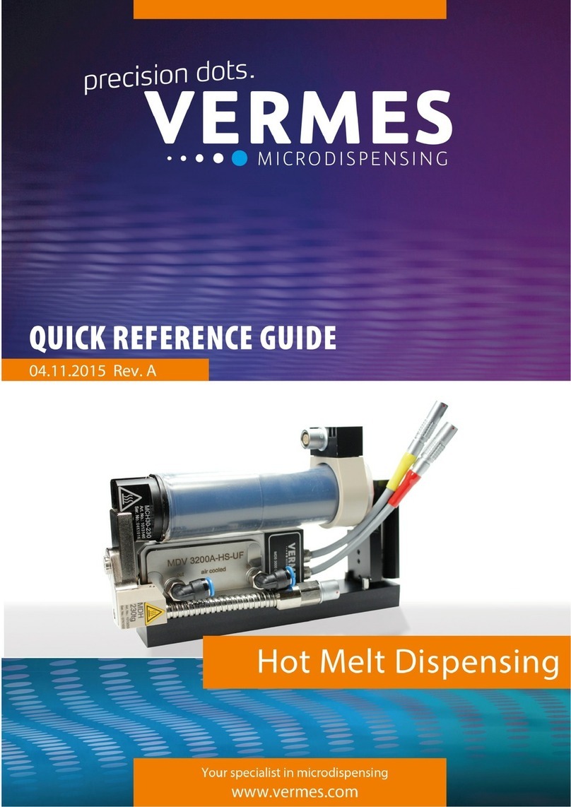
Vermes MDS 3000 Series User manual


VTK‐VS‐BA‐004e‐B|UserManualMDS3200A | Introduction 2
Content
1Introduction................................................................................................5
1.1TheMDS3000ProductFamily.................................................................................................5
2GeneralInstructions....................................................................................6
2.1PreliminaryNotes.....................................................................................................................6
2.2Legend......................................................................................................................................6
2.2.1DangerSymbols........................................................................................................................6
2.2.2DangerLevels...........................................................................................................................6
2.2.3IllustrationConvention.............................................................................................................7
2.2.4Abbreviations...........................................................................................................................7
2.3Tools.........................................................................................................................................8
2.3.1MDT301UniversalTool...........................................................................................................8
2.3.2MDT302NozzleAdjustingTool...............................................................................................8
2.3.3MDT303NozzleInsertChangingTool.....................................................................................8
2.3.4MDT304NozzleInsert‐SqueezingOutTool...........................................................................8
2.3.5MDT310TappetChangingTool...............................................................................................9
2.3.6MDT312TappetSealingToolFX..............................................................................................9
2.3.7HexagonSocketKeySet...........................................................................................................9
2.4Torques.....................................................................................................................................9
3SafetyNotes..............................................................................................10
3.1ObligationsandLiability.........................................................................................................10
3.1.1ObligationsoftheCustomer..................................................................................................10
3.1.2ObligationsoftheOperator...................................................................................................10
3.2ResidualRisks.........................................................................................................................10
3.3ContractedUse.......................................................................................................................11
3.4SpecificationandTechnicalNotes..........................................................................................12
3.5Warnings................................................................................................................................12
3.6QualificationsofOperatorsandMaintenancePersonnel......................................................13
3.7ProtectiveEquipmentandSafetyClothing............................................................................13
4ProductDescription..................................................................................14
4.1ControlUnitMDC3200A........................................................................................................14
4.1.1TechnicalData........................................................................................................................14
4.1.2FrontSide...............................................................................................................................15
4.1.3BackSide................................................................................................................................16
4.2FunctionKeys.........................................................................................................................17
4.3MenuStructure......................................................................................................................19
4.3.1MainMenu.............................................................................................................................19
4.3.2Submenu“PulseParameter“..................................................................................................19
4.3.3Submenu“Heating“................................................................................................................20
4.3.4Submenu“Status“..................................................................................................................20
4.4MemoriesoftheMDC3200A.................................................................................................21
4.5MicrodispensingValveMDV3200A.......................................................................................22
4.5.1Composition...........................................................................................................................22
4.5.2DetailDrawingMDV3200AwithMDX3080‐CC‐10...............................................................23
4.5.3Specification...........................................................................................................................23
4.5.4ValveTypes.............................................................................................................................24
4.5.5SpecialFeaturesoftheMDV3200A.......................................................................................25
5InitialOperation........................................................................................26

VTK‐VS‐BA‐004e‐B|UserManualMDS3200A | Introduction 3
5.1Delivery..................................................................................................................................26
5.1.1Unpacking...............................................................................................................................26
5.1.2Content...................................................................................................................................26
5.2AssemblingtheMDV3200A...................................................................................................27
5.3InstallationoftheMDS3200A...............................................................................................27
5.3.1InstallationoftheMDC3200A...............................................................................................28
5.3.2InstallationoftheMDV3200AValve.....................................................................................29
5.3.3Connectionofair‐coolingforMDV3200A‐ACmodels...........................................................29
5.3.4WiringoftheMDS3200A.......................................................................................................29
5.3.4.1ActuatorCable........................................................................................................................30
5.3.4.2SensorCable...........................................................................................................................30
5.3.4.3MainsCable............................................................................................................................30
5.4TheAdjust..............................................................................................................................31
5.4.1Purpose..................................................................................................................................31
5.4.2Procedure...............................................................................................................................31
5.5InitialLiquidSupply................................................................................................................32
5.6RemovingAirInclusionsfromtheSystem..............................................................................32
5.7ParameterInputandStart.....................................................................................................32
6Operation..................................................................................................33
6.1Triggeringadispensesequence.............................................................................................33
6.2DispensingandPositioningofaMultitudeofDots................................................................33
6.3ParametersforDispensingProcess........................................................................................34
6.4MinimumandMaximumValuesofParameters....................................................................35
6.5InputofValues.......................................................................................................................36
6.6SavingParameterSets............................................................................................................36
6.7RetrievingParameterSets......................................................................................................36
6.8LoadingtheFactorySettings..................................................................................................37
6.9SwitchingOFFtheMDS3200A...............................................................................................37
7CommunicationInterfaces........................................................................38
7.1SerialInterfaceRS‐232C:9‐PinSub‐D....................................................................................38
7.1.1FunctionsAllocatedtothedifferentPins...............................................................................38
7.1.2RS‐232CCommands...............................................................................................................39
7.1.3MDCCommunicatorSoftware...............................................................................................50
7.1.3.1Installation..............................................................................................................................50
7.1.3.2Start........................................................................................................................................50
7.1.3.3InputofCommandsandParameters.....................................................................................50
7.2PLC‐Interface:15‐pin,Sub‐D..................................................................................................51
7.2.1FunctionofPins......................................................................................................................51
7.2.2RemoteAdjust........................................................................................................................52
7.2.2.1Purpose..................................................................................................................................52
7.2.2.2Advantages.............................................................................................................................52
7.2.2.3Procedure...............................................................................................................................52
8Cleaning....................................................................................................53
8.1PreliminaryNotes...................................................................................................................53
8.2CompatibilitybetweenSealingMaterialandSelectedMedias..............................................54
8.3CleaningMethods..................................................................................................................55
8.3.1Pre‐purifying...........................................................................................................................55
8.3.2RinsingwithaPurifyingAgent................................................................................................56
8.3.3DismantlingtheValveandFinePurification..........................................................................57

VTK‐VS‐BA‐004e‐B|UserManualMDS3200A | Introduction 4
8.3.4FinePurificationofComponents............................................................................................58
9Maintenance.............................................................................................59
9.1MaintenanceIndicator...........................................................................................................59
9.2ExchangeofTappetSealing....................................................................................................59
9.3MaintenanceoftheTappet....................................................................................................60
9.3.1TheCT‐tappet(ceramicstappet)............................................................................................60
9.3.1.1Demounting............................................................................................................................60
9.3.1.2Installation..............................................................................................................................60
9.3.1.3DisassemblyandCleaning......................................................................................................60
9.3.1.4GreasingandRemounting......................................................................................................61
9.3.2TTF‐andCTF‐tappet...............................................................................................................61
9.3.2.1Demounting............................................................................................................................61
9.3.2.2Installation..............................................................................................................................61
9.3.2.3DisassemblyandCleaning......................................................................................................61
9.3.2.4GreasingandRemounting......................................................................................................61
10ErrorMessages.........................................................................................62
11Transport,StorageandDisposal................................................................66
11.1Transport................................................................................................................................66
11.2Storage...................................................................................................................................66
11.3RecyclingandDisposal...........................................................................................................66
12SpareParts................................................................................................67
13Attachment...............................................................................................71
13.1ECDeclarationofConformity.................................................................................................71
13.2DimensionalDrawingMDC3200A.........................................................................................72
13.3DimensionalDrawingMDV3200AwithMDX3080‐CC..........................................................73
13.4ConnectionDiagramPLC‐Interface........................................................................................74
13.5DeclarationConcerningDecontaminationofShippedEquipment........................................75
1Index.........................................................................................................76

VTK‐VS‐BA‐004e‐B|UserManualMDS3200A | Introduction 5
1INTRODUCTION
WithamicrodispensingoftheMDS3000linefromVermesMicrodispensingyouhaveboughta
highqualityproduct,assembledwiththeutmostcare.Duetotheiroutstandingqualitystandard
andthelong‐standingexperienceoftheteaminregardstoelectronicdevicesandpiezocontrols,
theseproductsprovidehighestfunctionalityandreliability.
Thankyouverymuchforyourtrustinus.
Wewillnowshowyouhowtoassembleandusethemicrodispensingsystem.Inordernottoim‐
pairtheinherentsafetyconceptofthesystem,proceduresdescribedinthismanualhavetobefol‐
lowedconsequentlyduringinstallationandoperation.
Readthismanualbeforeyoustarttheassemblyandalwaysconsultitduringtheuseofthe
microdispensingsystem.Startwiththechapter“SafetyNotes”(seepage10).Thiswillhelptopre‐
ventanyproblemsfortheuserortheequipment.
Theequipmentshouldneverbehandedovertopersonsignoringthebasicrulesforpreventionof
accidentsandtheinstructionsofthismanual–damagesresultingfromabuse,misuseandimprop‐
erhandlingarenotcoveredbytheguarantee.Inthecaseoffurtherquestions,consultourTech‐
nicalSupport.
TechnicalSupportVERMESMicrodispensingGmbH
PalnkamerStr.18
83624Otterfing
Tel.: +49(0)8024644‐26
Fax.: +49(0)8024644‐19
www.vermes.com
ServicehoursMonday‐Friday9.00to17.00(CET).
1.1 TheMDS3000ProductFamily
TheMDS3200AmodelrepresentsamemberoftheMDS3000productfamily,specializedinmost
accuratedispensinganddesignedforflexibleusewithsubstancesoflow,mediumandhighviscosi‐
ty(upto2.000.000mPas),whetherunfilledorfilled(evenwithabrasivecomponents).Applications
canbefoundinthefieldsofSMTandpharmaceuticsandintheproductionofelectronics,semi‐
conductorsandphotovoltaicmodulesandmanymore.
EachmicrodispensingsystembelongingtothisMDS3000productfamilyiscomposedofahigh
precisionvalvebasedonapiezoelectricelement(MDVseries),acontrolunit(MDCseries)andan
optionalselectablesupplyunit(MDXseries).
Duetoitscompactmodulardesign,thesystemcanquicklybeintegratedintoanyexistingproduc‐
tionenvironmentwithoutmajorpreparatorywork.Achangeintheproductionline(e.g.amodifi‐
cationoftheliquidtobeprocessed)iseasilypossible,sinceallofthedispensingparametersare
adjustableinalargerange.Fine‐tuningofthesequencethereforeispossibleanytime.Thesystem
allowsforreproducibleproportioningofhundredsofidenticalsingledots(<2nl)orbeadswithina
fewseconds.
Acomprehensivechoiceofaccessoriesisavailable,e.g.nozzleinserts,tappets,sealsandsupply
units,sothatthesystemcaneasilybeadaptedtonewchallengesanytime,withoutgivingriseto
majorinvestment.

VTK‐VS‐BA‐004e‐B|UserManualMDS3200A | General Instructions 6
2GENERALINSTRUCTIONS
Thischaptersummarizesthecontentofthismanualandcontainsgeneralinformationfortheuser.
2.1 PreliminaryNotes
Eachstepofinstallation,operationandmaintenancehastobeperformedinaccordance
withthismanual(somepicturesmaydifferslightlyfromtheactualproduct).
Youcanfindinformationaboutsafetyaspectsandanefficientuseofthesysteminthe
concerningchapters.
Thismanualrepresentsanintegralpartofthedeliveryandmustbemadeavailableto
everyuserworkingwiththeMDS3200A.Alwayskeepitinclosevicinityofthe
machine.
Itmustbepreserveduntiltheendofthelifetime.
2.2 Legend
2.2.1 DangerSymbols
PictogramExplanation
ToxicSubstances
DangerOriginatingfromElectricity
ExplosionHazard
PotentialDanger
ImportantNote
Information
RefertoUserManual
2.2.2 DangerLevels
InstructionPossibleConsequences
DANGER!
Thedamageisimminent.Iftheoperatingprocedureisnotstrictly
observed,thissituationmayresultindeath,considerablematerial
damageorenvironmentalcontamination.
WARNING!Thedangerofdeathandseriousinjuringcannotbeexcluded.
CAUTION!Dangerofinjuries.
IMPORTANTNOTE!Anoperatingprocedurewhich,ifnotstrictlyobserved,mayresultin
damagetotheequipment,unexpectedinterruptionsorshutdown.
INFORMATION!Supplementaryrecommendationforaneconomicalandtime‐saving
useoftheequipment.

VTK‐VS‐BA‐004e‐B|UserManualMDS3200A | General Instructions 7
2.2.3 IllustrationConvention
SymbolExplanation
Step1:
Step2:
Step3:
Thesequencemustbefollowedincorrectorder
Eachstepofthissequenceismandatory,noneofthemshouldbeomitted
Directionofmovement
Lists
[…]Symbolforakeyonthekeypad
2.2.4 Abbreviations
Abbr.Fullname
NINozzleinsert
NUNozzleunit
NU‐fixNozzleunitwithfixation
NANNozzleadjustmentnut
NAN‐fixNozzleadjustmentnutwithfixation
MDCController(MicroDispensingControlunit)
MDFFluidbox(MicroDispensingFluidbox)
MDSMicroDispensingSystem
MDVValve(MicroDispensingValve)
MDXSupplyunit
PLCProgrammablelogiccontroller
TGTappetguidance

VTK‐VS‐BA‐004e‐B|UserManualMDS3200A | General Instructions 8
2.3 Tools
ThefollowingtoolsarerequiredtoinstallandtooperatetheMDS3200A:
MDT301Universaltool(Partno.1010208)
MDT302Nozzleadjustingtool(Partno.1009289)
MDT303Nozzleinsertchangingtool(Partno.1007083)
MDT304Toolforsqueezingoutnozzleinserts(Partno.1007085)
MDT310Tappetchangingtool(Partno.1008344)
MDT312ToolfortappetsealingFX(Partno.1012825)
Hexagonsocketkeyset(Partno.1012993)
Whenyouordertools,alwaysspecifythepartnumberoftherequireditem.
IMPORTANTNOTE!(Noforeigntools)
Donotuseauxiliarytoolsorforeignproducts,otherwisedamagestotheequipment
mightbepossible.
2.3.1 MDT301UniversalTool
ThetoolMDT301consistsoftwosubcomponentsscrewedtoeachother:
“Sealmounter“withamandreltoinsertandtoremovethetappetseal(1.)
“Adjustmentgrip“withareceptacleforthenozzleadjustingnut(2.)
IntendedPurpose:
1. Fixingandremovingoftappetsealingandtappetcenteringpiece
2. Itmayalsobeusedtoexecutethegeneraladjust
(alternativelytotoolMDT302describedbelow)
2.3.2 MDT302NozzleAdjustingTool
Thisparthasareceptacleforthenozzleadjustingnutandalongerleverto
simplifythegeneraladjust.ItcanalsobeusedincombinationwithMDT310,if
abetterleverageisneeded.
IntendedPurpose:
1. Performingtheadjust
2. Fixingthetightingscrewtothefluidbox
3. ChangingoftappetincombinationwithMDT310
2.3.3 MDT303NozzleInsertChangingTool
TheMDT303isrequiredfortheexchangeofthenozzleinsert.The3pinsof
theMDT303gripintothereceptacleboresofthetappetguidanceinorder
tounscrewthetappetguidancefromthenozzleadjustmentnut.
IntendedPurpose:
1. Screwingapartnozzleadjustingnutandtappetguidancewhenchanging
thenozzleinsert
2.3.4 MDT304NozzleInsert–SqueezingOutTool
ThediametersoftheendpiecesoftoolMDT304arenotidentical,aseachof
themisusedforadifferentpurpose:
IntendedPurpose:
1. Squeezingoutofthetappetsealingbetweenfluidboxandactuator(1.)
2. Detachingthenozzleinsertfromthetappetguidance(2.)

VTK‐VS‐BA‐004e‐B|UserManualMDS3200A | General Instructions 9
2.3.5 MDT310TappetChangingTool
TheMDT310featuresaborewithtwostuds,servingasareceptacleforthe
tappet.Whenexchangingthetappet,carefullypushitintothisboreuntilthe
studslatchintothegroovesofthetappetcenteringscrew.Thenthecentering
screwcanbeinsertedorremovedbyrotatingthetool(whileapplyingalight
constantpressure).
IntendedPurpose:
1. Removingthepresenttappetandfixinganewone
2.3.6 MDT312TappetSealingToolFX
TheMDT312consistsofatoolbodyandanejectorpin.Itismeantfor
mountinganddismountingthetappetsealingFX,especiallyformounting
ordismountingthetappetsealingbushingFX.
IntendedPurpose:
1. MountingthebushingofthetappetsealingFX
2. Disengagingofthetoolitself(attheendoftheprocedure)
2.3.7 HexagonSocketKeySet
Thesetincludesthreekeys(sizes2,2.5and3)forhex‐screws,withblades
madeofhardenedsteelandergonomicgrips.
IntendedPurpose:
1. Mountinganddismountingthefluidbox(2)
2. Mountinganddismountingthetappetguard(2)
3. Mountinganddismountingthecartridgeholder(2.5)
4. InstallationofheatertypeMDH‐230te(2.5)
5. Fixingofthevalve,in‐situ(3)
2.3.8 Torques
ElementTorquemin.(Nm)Torquemax.(Nm)
Screwsforfluidbox(M2,0x8)0,81
TightingscrewforMDF3070‐CC1,21,4
FluidboxconnectorLuer‐Lock1,01,2
TappetguidancePEEK0,40,6
TappetguidanceH0,81
Tappetcenteringscrew1,01,4
TStappet0,220,22

VTK‐VS‐BA‐004e‐B|UserManualMDS3200A | Safety Notes 10
3SAFETYNOTES
Thischaptersummarizesthegeneralsafetyaspectsofthesystem.Furtherpointstobeobserved
areemphasizedinthecorrespondingsubchapters.
3.1 ObligationsandLiability
Inordertoprotectthehealthofpersonnelandtoavoidunnecessarydamage,alloftherecom‐
mendationsofthemanufacturerwithregardtosafetymustbeexplainedtoeverymemberofthe
teamtakingpartininstallation,operationormaintenanceofthesystem.
VERMESMicrodispensingdoesnotacceptanyliabilityformaterialdamagesorpersonalinjuryorig‐
inatingfrominappropriateuse,violationofsafetyprescriptions,oranyprocedureinconsistentwith
theinstructionsofthismanual.Thegeneralrulesforpreventionofaccidentsaswellaslocalenvi‐
ronmentalregulationsmustbeinplaceandthoroughlyfollowedbythepersonnel.
3.1.1 ObligationsoftheCustomer
Inviewofatrouble‐freeoperationofthemicrodispensingsystem,thecustomerhastoselecthis
personnelcarefully:
Unauthorizedusemustbeprevented.Personsignoringthefundamentalrequirementsof
industrialsafety,environmentalprotectionandpreventionofaccidentsarenotallowed
toworkwiththesystem.
Newoperatorsmustbeinstructedandtrainedcorrespondingly,sothattheycanunder‐
standandputintopracticetheinstructionsofthismanual.Forcertainmeasures,apar‐
ticularqualificationmayberequired.
Themanualmustremainaccessibleanytime.
3.1.2 ObligationsoftheOperator
Allpersonsinchargeofthesystemmust:
Continuouslyrespectthegeneralrulesforpreventionofaccidents.
Beawareofthesafetynotesofthismanual.Thisisnecessaryalsoforoperatorstrained
bythemanufacturerorexperiencedinworkwithsimilarsystems.
Consultthemanufacturerinanycaseofdoubt.Applicationsbeyondthescopeofthe
specificationandimprovisedrepairworkmustbeavoided.
3.2 ResidualRisks
Themicrodispensingsystemhasbeendevelopedanddesignedwiththecommonrequirementsof
safetyinmind,andcorrespondstothecurrentstateoftechnology.Inthedeliveredlayout,itcom‐
plieswiththefollowingregulationsanddirectives:
2006/42/ECMachineryDirective
2006/95/ECLowVoltageDirective
2004/108/ECElectromagneticCompatibility
2002/95/ECRestrictionoftheUseofCertainHazardousSubstancesinElectricalandElec‐
tronicEquipment(RoHS2003‐01‐27)
DINEN61010‐1(VDE0411)SafetyRequirementsforElectricalEquipmentforMeasure‐
ment,ControlandLaboratory
DINENISO12100‐1andDINENISO12100‐2SafetyoftheMachinery,FundamentalTerms
DINEN60204‐1(VDE0113)SafetyoftheMachinery,ElectricInstallationsofMachinery,
Part1,GeneralRequirements
DINEN982SafetyRequirementsforFluidPowerSystemsandtheirComponents–Hydraulics.

VTK‐VS‐BA‐004e‐B|UserManualMDS3200A | Safety Notes 11
Despitethiscomprehensiveinherentsafetystructure,theoperationofthemicrosdispensingsys‐
temMDS3200Amayentaildanger
Forthehealthoftheoperatororathirdparty,
Forthesystemitself,
Orgiverisetoanothermaterialdamage.
Thereforetheusehasstrictlytobelimited:
Totheintendedapplication,
Toastateinwhichthetechnicalsafetyofthesystemcanbeguaranteed(i.e.itisstrictly
forbiddentostartorcontinuetheoperationwheneveradefecthasbecomeobvious).
Problemswithapotentialtoimpairsafetyaspectsmustbesolvedimmediately.Forthisreason,it
isimperativethatthismanualremainsaccessibleanytimewithoutdelay.Inanemergencysitua‐
tion,ashortreactiontimemaybecrucial.
Ifthesystemistransmittedtoanyotherdepartmentorinstitution,itmustbeaccompaniedby
thismanual.
3.3 ContractedUse
ThesystemMDS3200Ahasbeendesignedforultra‐precisecontactlessdispensingoffluidsina
largerangeofviscosity(upto2.000.000mPas),inunfilledorfilledstate(alsowithabrasiveex‐
tenders),tobeoperatedinaconvenientlyequippedindustrialorlaboratoryenvironment.
Deviationsfromtheinstructionsofthismanualmustexplicitlybeauthorizedbythemanufacturer
(inwriting);otherwisehisliabilitywithregardtotheguaranteebecomesnullandvoid.
Thisincludes:
Extensionsandchangesofdesign
Modificationsofthesystem,orsparepartsnotrecommendedbythemanufacturer
Inappropriatematerialselection(lackofcompatibilitybetweenpartsanddispensedfluids)
Operationwithdamagedpartsorafterimprovisedrepair
Dispensingoffluidsabletoaffectthefunctionalityofthesystem(incaseofdoubt,con‐
sultmanufacturer)
Manipulationorabsenceofintegratedsafetydevicesorsealings
Repairbypersonsorenterprisesnotauthorizedbythemanufacturer
Operationbeyondthescopeofthespecification
Auxiliaryequipmentnotrecommendedbythemanufacturer
Thesystemisnotadmittedforapplicationsinhazardouslocations(ATEXzones)
Innoeventshallwebeliableunderourguaranteeoranyotherprovisionoftheagreementfor
damagesresultingfromaviolationoftheinstructionsofthismanual.
Forfurtherquestionsconcerningcurrentapplicationsandmodificationsofthesystemwithrespect
tonewrequirements,contactthemanufacturer,theresponsiblesalespartnerortheTechnical
Support.

VTK‐VS‐BA‐004e‐B|UserManualMDS3200A | Safety Notes 12
3.4 SpecificationandTechnicalNotes
Themaximumfrequencyof2kHzandtheaveragefrequencyof580Hzshouldneverbe
exceeded.
Thesystemisdesignedforinterioruseonly.Maximumaltitude:2000m.
AirHumidity:35%till95%rH
Temperature:10°Ctill50°C
Admissiblemainsvoltagefluctuations:Withintherangeof±10%ofratedvoltage.
TransientovervoltagetoleratedaccordingtoIEC60364‐4‐443,max.degreeofsoiling:2
Mainscablesmustfeatureaprotectiveconductor.Inthecaseofcablesnotdelivered
byVermesMicrodispensing,theguaranteefortheMDS3200Aisvalidonlyupfromthe
interface.
Poweroutletsmustcomplywithcommonsafetyprescriptions.
Duringtheapplication,sufficientaircirculationmustbeguaranteed.
Forfurtherdetails,refertoInstallationchapter(page27).
Coolingisachievedbycompressedair,freeoffineparticles,dust,oilandcondensate,
qualityclasses1,3,2acc.toDIN/ISO8573‐1.
Solidparticles:0,1µmmax.,admissibledensity:0,1mg/m³=Qualityclass1
Watercontent:max.pressuredewpoint‐20°C.Watercontent:0,88g/m³=Qualityclass3
Residualoil:0,1mg/m³max.=Qualityclass2
3.5 Warnings
Handlethemainscablecorrectly:Alwaysseizethecableattheplug.Nevertouchitwith
wethands.
Thecableshouldneverbesqueezedorkinked.Neverplacetheinstrumentation(orany
otherobject)onthecable.
Damagedcablesmaygiverisetofireanddangercausedbyelectricity.Inspectthemvis‐
uallyinregularintervals.Youshouldexchangedamagedpartsatonce.
Inthecaseofamajordisturbance,disconnecttheequipmentimmediatelyfromthe
mains.
Sparepartsnotdeliveredorrecommendedbythemanufacturermayaffecttheinherent
safetyofthesystem.Thesameproblemarises,ifthecustomerattemptstoprocesssub‐
stancesnotadmittedforthedispensingsystem.
Unqualifiedrepairworkoftencausesmajordamages,evenwithpersonalinjury.
ThereforerepairisreservedtoourTechnicalSupportandauthorizedsubcontractors.
Beforeremovingtheactuatorandsensorcables,thesystemmustbeswitchedOFF.
Forlongerinterruptions,switchOFFthecontrolunit.
BeforedisconnectingtheMDC3200Afromthemains,switchitOFF.
RepeatedlyswitchingONandOFFtheequipmentmayreducethelifetimeofthepowerunit.
Beforechargingthefluidsystemwithanaggressive,reactiveortoxicsubstance,itmust
beverifiedthatitiscompatiblewithallofthecontactingcomponentsinsidethesystem.
Thesupplypressureatthecartridgeorinthepressuretankof7barresp.70bar(accord‐
ingtothesystemconfiguration)shouldneverbeexceeded.
Whencleaningthecomponentsincontactwiththetransportedsubstance,thedevice
shouldbeplacedinasafeandstableposition,withoutbeingsubjectedtovibrations.
Tocleantheactuator,aclothnotfluffyandlightlymoistened(e.g.byIsopropanol)isrec‐
ommended.Duringthecleaningprocedure,noliquidshouldpenetrateintotheactuator
itself,e.g.throughtheplug.

VTK‐VS‐BA‐004e‐B|UserManualMDS3200A | Safety Notes 13
TheMDV3200AisdesignedaccordingtotheNormallyOpenprinciple.Thereforethe
valveisnormallyopenandthetransportedliquidcanflow.BeforeswitchingOFFthe
microdispenser,donotforgettolowerthesupplypressuretoatmosphericpressure.
3.6 QualificationsofOperatorsandMaintenancePersonnel
Themicrodispensingsystemtogetherwithallattachedaccessoriesshouldonlybeusedbycompe‐
tentpersonnelwithanadequatequalification.Theymustknowandunderstandthecontentofthe
manual.Wedosupposethatthedepartmentheadisawareofpossibledangers,andcorrespond‐
inglyassignsthetaskstopersonsabletoexecutetheirworkinaresponsiblemanner.
AccordingtoDINVDE0105andIEC364qualifiedpersonnelreferstomembersoftheteamwitha
sufficientknowledgeofrelevantnorms,directivesandrulesforpreventionofaccidents.Theyneed
thequalificationandexperiencenecessary,sothattheyareinapositiontorealizeandtoprevent
possibledangersalreadyatanearlystage.KnowledgeinFirstAidandadirectcontacttothelocal
emergencyunitsisrequiredaswell.
3.7 ProtectiveEquipmentandSafetyClothing
Youshouldalwayswearsuitableprotectiveequipment,wheneverhandlingordispensingaggres‐
sive,reactiveortoxicsubstances.Thesameisvalidinthepresenceofahighsupplypressure.
Thismaycomprise:
Safetyglasses
Abreathingapparatus
Anoverallandglovesresistanttothecorrespondingchemicalfluid
WhenyouworkinthedirectvicinityoftheMDS3200Aforaprolongedperiod,
youshouldalsowearearprotection.

VTK‐VS‐BA‐004e‐B|UserManualMDS3200A | Product Description 14
4PRODUCTDESCRIPTION
ThischaptercontainsrelevantinformationaboutthecontrolunitMDC3200AandthevalveMDC
3200A.Itdescribesthemenustructure,keypadandfunctionsofthecontrolunit,aswellasthe
structureandthehardwareconfigurationofthevalve.
4.1 ControlUnitMDC3200A
4.1.1 TechnicalData
Dimensions 128mmHx102mmWx173mmD(w/ocable)
128mmHx102mmWx185mmD(withcable)
3HEx20TE
Weightca.1500g
SupplyVoltage110/230VAC/DC
SupplyFrequency50/60Hz
CurrentConsumption900mAmax.
Duringstart‐up,thisvaluemaybeincreasedbya
factorof5(start‐uppeak).
Recommendedfuse:16Afor240Vresp.110V
OperatingTemperature0°Cto50°C
AirHumidity35%till95%rH
CasingTypePlug‐incasefor19“rack
ColorofCasingBlack,withlighterfrontplate
VentilationConvection
Internalstoragelocations:10(seepage21)
Displaylines2lineswith16characterseach
DisplayilluminationWhitewithbackgroundlighting
Keypad12softkeys
ColorofkeysBlue
Controllamps(Frontside)1xHeatingcircuit(red)
1xServicerequest(red)
1xAdjustOK(green)
1xAdjustnotOK(red)
Controllamps(Backside)1xIlluminatedpowerlamp
Plugcontacts(Backside)1xMainsplug(110/240VAC)
1x9pinSub‐DRS‐232C
1x15pinSub‐DPLC
1xAux‐output24V
1xSensorsocket
1xActuatorsocket
1xSocketforheating
1xThermocouplesocket

VTK‐VS‐BA‐004e‐B|UserManualMDS3200A | Product Description
15
4.1.2 FrontSide
LC‐Display(twolineswith16characterseach):
Data,serviceintervalsandmenuoptionsareshowninthetwolinesoftheilluminatedLCdisplay.
Thecurrentmenuoptionappearsintheupperline,whereasthelowerlinecontainsthecurrent
parametervaluefordispensing,accordingtonumericaldatatobemodified.
Keypadwithtwelvesoftkeys:
Menuoptionstocontrolthesystemareselectedbymeansofthesekeys.
Detailsforchangingparametersetc.areexplainedinchapter4.2,page17.
Controllampforservicerequest:
Assoonasthislamplightsup,thevalvehastobereturnedtothemanufacturer(orlicensedsub‐
contractor)forregularperiodicmaintenance.
Controllampsforadjust:
Theadjustforthevalveisinternallymonitored;theresultisvisualizedbymeansofthesetwocontrol
lamps.
Green:ThevalueisOKandcanbeconfirmedby[enter].
Red:Thevalueistoohighandmustbeloweredaccordingtotheinstructionsofthismanual,seepage31.
Controllampforstatusofheating:
ThisredLEDindicatestheactivityoftheheating.ON,Heatingactivated,otherwiseOFF.

VTK‐VS‐BA‐004e‐B|UserManualMDS3200A | Product Description 16
4.1.3 BackSide
Thermocouplesocket:
Thiselementisintendedforconnectionofthermocouples“TypeK“.
Mainsswitch:
WiththisilluminatedswitchtheunitisswitchedONandOFF.
AUXsocket:
Thisconnectorcanbeusedforsupplyofanexternaldevice(e.g.anoptocoupler).
Socketforheating:
Theheatercablehastobeconnectedhere.
RS‐232CInterface(9‐pin):
SincethesystemoffersthepossibilityofexternalprogrammingofdispensingparametersviaPC,a
localRS‐232Cisintegratedtoreceivethedata.Forthecommunicationprotocol,refertopage38.
Sensorsocket:
Fortheconnectionofthesensorcable.
Actuatorsocket:
Fortheconnectionoftheactuatorcable.
PLCInterface(15‐pin):
Differentinputsandoutputsmaybeconnected.Forthecommunicationprotocol,refertopage51.
Shackleforthemainscable:
Securesthemainscableagainstslippingoff.
Mainsconnector:
Connectsthecontrolunittopowersupply.

VTK‐VS‐BA‐004e‐B|UserManualMDS3200A | Product Description 17
4.2 FunctionKeys
FunctionKeyFunction
ManualTriggerKey
Pressingthe[trig]‐keyinstantaneouslylaunchesadispensingprocedureac‐
cordingtotheselectedparametersettings.
The[save]‐keyopensthemenuforstoringcurrentparameters.Tenstorage
locationsareavailablefordistinctconfigurationsets.Eachsetcontainsvalues
forpulseparametersandthesettingsforheatingandkeyinterlock.
Selectthedesiredstoragelocationbymeansofarrowkeys.
Presstoconfirm.
Presstocancelwithoutsavingtheselection.
Parametersetssavedintheinternalmemorycanberetrievedanytimeusing
the[recall]‐key.
Selectoneoftheteninternalstoragelocationsbyarrowkeys.
Presstoconfirmtheselection.
Presstoabort.
The[adj]‐keyisusedtostarttheadjust(seepage).Itisrequiredduringeach
initialoperationandafteranexchangeofthenozzleunit.
Withthisprocedurethepositionofthenozzleinsertwithrespectto
thetappetispreselected.
Pressingthe[enter]‐keyconfirmsthemenuselectionandopensthecorre‐
spondingsubmenu.
...or...
Theentryofavalueisconfirmed,andthescreenchangestothenext‐higher
menulevel.
Pressingthe[esc]‐keyabortsthecurrentaction,valuesjustenteredaredelet‐
ed.Thenext‐highermenulevelopens.
...or...
Directaccesstothenext‐highermenulevel.
Accesstothenext‐highermenulevel.
...or...
Increasingofanumericalvalue.
Accesstothenext‐lowermenulevel.
...or...
Reductionofanumericalvalue.

VTK‐VS‐BA‐004e‐B|UserManualMDS3200A | Product Description 18
Thescreenmovesonemenustepback.
...or...
Thecursorisshiftedonepositiontotheleft.
...or...
Aparameterismodified.
Thescreenmovesonemenustepahead.
...or...
Thecursorisshiftedonepositiontotheright.
...or...
Aparameterismodified.
The[F1]‐keyopensthevalve,takingintoconsiderationthecurrentvaluesfor
“Rising”and“Falling”.Thevalveremainsopened,untilthekeyisreleased.
Maximumlength:2min.Thenthevalveclosesautomaticallyinordertopro‐
tecttheactuator.
Notusedinthepresentconfiguration.

VTK‐VS‐BA‐004e‐B|UserManualMDS3200A | Product Description 19
4.3 MenuStructure
Threemenuscanbeaccessedfromthemainmenu:
“PulseParameter“,“Heating“and“Status“.
Youcanrecallandmodifydispensingparametersforaparticularprocessinthesubmenu
“PulseParameter“.
“Heating“–selectthesettingsfortheheating.
RelevantdataforourTechnicalSupportarecontainedinsubmenu“Status“.Thisfunctioncan
alsobeusedbytheclienttodecideonindividualcyclesforthereplacementoftappetandnoz‐
zleinsert(seepage59).Thecurrentstateofthesystemwithrespecttothemaintenanceinter‐
valcanbeverifiedbyfunction“Maint.Cycle“(seepage59),messagesconcerningthecorrect
behaviorofthesystembyfunction“Error“.Troubleshootingisdetailedinchapter10.
4.3.1 MainMenu
4.3.2 Submenu“PulseParameter“

VTK‐VS‐BA‐004e‐B|UserManualMDS3200A | Product Description 20
4.3.3 Submenu“Heating“
Twodistinctoptions(MDH230teandMDH230tf)areavailabletoheatthenozzlesofthe
microdispenserMDS3200A.Thiswaythedynamicalviscosityofthefluidtobedispensedcanbe
controlled,forsomeliquidsdispensingwithoutheatingisevenimpossible.
Heatingmayalsoberequiredtoensureaconstantprocesstemperature,orwhenthedispensing
hastotakeplaceaboveroomtemperature.
SelectionoftemperaturevaluesaswellasswitchingONandOFFoftheheatersiscarriedoutby
meansofthefunctionsillustratedbelow.
4.3.4 Submenu“Status“
Thefirstthreefunctions“Firmwareversion“,“ValveID“and“IDControlUnit“withtheparticular
serialnumbersrepresentimportantinformationwhenconsultingtheTechnicalSupport.
“Maint.Cycle”referstotheunitasawholeandcannotbemodifiedbytheuser.Forthenozzleand
thetappethowever,itispossibletodetermineafixnumberofcyclesbeforereplacingtheconcern‐
ingitemsandtoresetthecountersafterexchange.“Error”showscorrespondingmessagesofthe
system.
This manual suits for next models
1
Table of contents
Other Vermes Dispenser manuals
Popular Dispenser manuals by other brands

Hupfer
Hupfer SDMS Typ I-1000 Assembly instructions

Kiwi
Kiwi KSD 9922 instruction manual

Kohler
Kohler 1400976-2-A installation instructions

Tork
Tork W6 Cleaning instructions

nedis
nedis KAWD100FBK quick start guide

SC Johnson Professional
SC Johnson Professional Stoko Vario mat Instructions and Mounting Manual