manuals.online logo
Brands
  1. Home
  2. •
  3. Brands
  4. •
  5. Chord
  6. •
  7. Amplifier
  8. •
  9. Chord SPM 650 User manual

Chord SPM 650 User manual

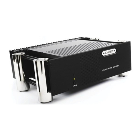
SPM 650 POWER AMPLIFIER MANUAL
OPERATING INSTRUCTIONS
INSTALLATION
Your amplifier should be positioned to ensure a free flow of air over the rear heat sink and through the upper and
lower grilles. When driven continuously at well above average listening levels, the temperature on the heat sink may
exceed 50oC. This is not a fault, but an indication of the need for adequate ventilation.
Please ensure that the IEC mains lead is correctly terminated.
UK/EUROPE Brown = LIVE = Black USA/CANADA
Blue = NEUTRAL = White
Yellow/Green = EARTH = Green
THE SPM 650 MUST BE EARTHED AT ALL TIMES VIA ITS OWN MAINS LEAD.
FAILURE TO DO THIS MAY BE HAZARDOUS.
CE This unit complies with EN 50081-1 & IEC 801/2
REAR PANEL
The two gold-plated phono-style connectors and XLRs are pre-amplifier inputs. Please connect these last, with the
amplifier switched off.
Right Left
It has come to light that, in some European
countries a hum may occur if Pre and Power
Amplifiers are connected to mains wall sockets
which do not have an earth. Please ensure
that, if this is the case, the pre and power
amps are connected via a multi-way mains
block which contains an earth point at each
socket outlet. This is to ensure that the chassis
metalwork of each item is connected together
and Chord Electronics Limited firmly
recommend that an earthing method for the
building is implemented.
OPERATION
When the amplifier is connected to the mains the LED immediately above the power switch will indicate red
(standby). When switched on, this LED will change to illuminate green (operational). There will be a delay of about
12 seconds before the output signal is fed to the loudspeakers, this is to allow the amplifier to stabilise.
In the event of a major overload or a short circuit across the output of any channel, the green "power on" LED will
indicate trip by fading and immediately re-illuminating to red standby mode. The amplifier will shut down
automatically and it should then be switched off. When the fault condition has been rectified, the amplifier can be
switched on and will power up as normal. A minimum period of eight seconds must be allowed to elapse between
switching off and switching on again. This is to allow the power supply protection circuitry to re-set itself.
There are no user serviceable parts in your SPM 650. It should only be serviced by Chord Electronics Limited or their
expressly approved Service Agents.
CARE AND CLEANING
The SPM 650 requires no special care other than common-sense. Spray window cleaner (clear type) may be used (if
first sprayed on to a soft cloth) to remove surface blemishes such as finger marks from the metal casing. Never spray
directly on to the amplifier and never use abrasive cleaning materials, use only a lint free soft cloth as described.
SERVICE INFORMATION
WARNING - The power supply components within this amplifier are designed to be operated at lethal voltages and
energy levels. Circuit designs that embody these components conform with applicable safety requirements.
Precautions must be taken to prevent accidental contact with power-line potentials. Do not connect grounded test
equipment.
NEW TECHNOLOGY
Much of what Chord has achieved is the result of using innovative, leading edge technology. For example, we believe
that we are unique in using the technique of ‘dynamic coupling’ of the power supply rails. Whatever transient
demand is presented to the amplifier stages, the positive and negative rails remain in perfect equilibrium, with each
compensating for the demands made on the other. This means that power delivery is always balanced and free from
ground loop modulation distortion.
This, combined with enormous reserves of instantly delivered, precisely controlled power is what makes the SPM 650
sound so effortless. The power supply rails operate well above that which most amplifiers can accommodate. This
and other advanced techniques enables the ultra high frequency low ESR power supply to store a great deal more
energy far more efficiently. Clipping is virtually impossible. Furthermore, compared to other amplifiers of a similar
power rating the SPM 650 weighs in at a mere 9Kg. Another new technique is used to protect the amplifier against
overload, internal and external short circuits. The output signal path is totally free of any fuses or sound-degrading
resistive components often employed for overload sensing. The SPM 650 is designed to surpass the highest European
safety and electromagnetic interference standards.
The amplifier sections are also highly sophisticated designs that make the most of the best high voltage, lateral
structure MOSFETs available, 2 x 300 watt devices per channel. Combining the subtlety and musicality of a good
valve design with the punch and accuracy of ‘state of the art’ solid state products. The result is a ‘sliding bias’ class
A/B design with all drive circuitry operating in class A. At usual listening levels, most of the music will be
reproduced in class A. Chord’s no-compromise design philosophy means there is no better built amplifier.
Individually hand-crafted, it is constructed to aerospace standards from the circuit boards up.
SPECIFICATIONS
SPM 650 POWER AMPLIFIER
OUTPUT POWER
130W rms per channel @ 0.05% distortion into 8,
170W rms per channel into 4, 200W rms into 2.
Thermal limitation only, 1 channel driven.
DYNAMIC HEADROOM
200W rms per channel into 8, 360W rms per channel into 4.
- 1 KHz, 10 cycles on, 90 cycles off.
FREQUENCY RESPONSE (8 OHMS)
-1dB, 0.2Hz to 46KHz
-3dB, 0.1Hz to 77KHz
FREQUENCY RESPONSE (4 OHMS)
-1dB, 0.2Hz to 39KHz
-3dB, 0.1Hz to 75KHz
SIGNAL TO NOISE RATIO
Better than -103dB, ‘A’ weighted two thirds power.
CHANNEL SEPARATION
Better than 95dB.
PRE-AMPLIFIER INPUT CONNECTION
2 x gold-plated fully-balanced XLR sockets. 2 x gold-plated custom
phono sockets, unbalanced.
INPUT IMPEDANCE
100k. Unbalanced/Balanced
INPUT CAPACITANCE
<30pf.
OUTPUT IMPEDANCE
0.02
OUTPUT INDUCTANCE
2.6H
OUTPUT CONNECTIONS
4 x 4mm rhodium binding posts (1 pair Black, 1 pair Red)
SLEW RATE
70V per S, 1KHz
20V square wave
GAIN
30dB.
STABILITY
Unconditional
DIMENSIONS (Standard)
420mm (w) x 355mm (d) x 88mm (h)
WEIGHT
9Kg
Made in England by:
Chord Electronics Limited, The Pump House, Farleigh Bridge, Farleigh Lane, East Farleigh, Kent.
ME16 9NB. United Kingdom.
Tel: 44(0)1622-721444 Fax: 44(0)1622-721555
CHORD
ChordElectronicsLimited

Other Chord Amplifier manuals

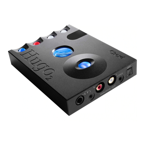
Chord Hugo2 User manual

Chord

Chord Hugo2 User manual

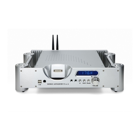
Chord Indigo Digital Preamplifier User manual

Chord

Chord Indigo Digital Preamplifier User manual

Chord Etude Instruction manual

Chord

Chord Etude Instruction manual

Chord CPA 2500 User manual

Chord

Chord CPA 2500 User manual

Chord Hugo2 User manual

Chord

Chord Hugo2 User manual

Chord TToby User manual

Chord

Chord TToby User manual

Chord PRIMA User manual

Chord

Chord PRIMA User manual

Chord 173.012UK User manual

Chord

Chord 173.012UK User manual

Chord TToby User manual

Chord

Chord TToby User manual

Chord CPM 2650 User manual

Chord

Chord CPM 2650 User manual

Chord Hugo TT 2 User manual

Chord

Chord Hugo TT 2 User manual

Chord CPA5000 User manual

Chord

Chord CPA5000 User manual

Chord BerTTi User manual

Chord

Chord BerTTi User manual

Chord ULTIMA 5 User manual

Chord

Chord ULTIMA 5 User manual

Chord CPA3000 User manual

Chord

Chord CPA3000 User manual

Chord DAVE User manual

Chord

Chord DAVE User manual

Chord ULTIMA 2 User manual

Chord

Chord ULTIMA 2 User manual

Chord CB-25 User manual

Chord

Chord CB-25 User manual

Chord Etude User manual

Chord

Chord Etude User manual

Chord Hugo User manual

Chord

Chord Hugo User manual

Chord TToby Instruction manual

Chord

Chord TToby Instruction manual

Chord Etude User manual

Chord

Chord Etude User manual

Chord SPM 600 User manual

Chord

Chord SPM 600 User manual

Chord PRIMA User manual

Chord

Chord PRIMA User manual

Popular Amplifier manuals by other brands

Kenwood KMF-X9000 Service manual

Kenwood

Kenwood KMF-X9000 Service manual

Pioneer SR-9 Service manual

Pioneer

Pioneer SR-9 Service manual

Cambridge Audio azur 840A supplementary guide

Cambridge Audio

Cambridge Audio azur 840A supplementary guide

MANBUTECH AMP-ACCORD-16-18 manual

MANBUTECH

MANBUTECH AMP-ACCORD-16-18 manual

Alpine PMX-T320 owner's manual

Alpine

Alpine PMX-T320 owner's manual

Manley Chinook owner's manual

Manley

Manley Chinook owner's manual

Alto STEREO TUBE PREAMP user manual

Alto

Alto STEREO TUBE PREAMP user manual

Biamp Tesira SERVER Operation manual

Biamp

Biamp Tesira SERVER Operation manual

NAD M33 owner's manual

NAD

NAD M33 owner's manual

Kenwood X301-4 instruction manual

Kenwood

Kenwood X301-4 instruction manual

Monacor IPA-222 manual

Monacor

Monacor IPA-222 manual

Klipsch ProMedia DD-5.1 user guide

Klipsch

Klipsch ProMedia DD-5.1 user guide

Audio Research Definition DS450M owner's manual

Audio Research

Audio Research Definition DS450M owner's manual

Audio General PA2X20 user manual

Audio General

Audio General PA2X20 user manual

Hartke G10 owner's manual

Hartke

Hartke G10 owner's manual

Sansui A-9 Service manual

Sansui

Sansui A-9 Service manual

Executive Audio ALPHA Series user manual

Executive Audio

Executive Audio ALPHA Series user manual

OSD Audio PAM 1270 manual

OSD Audio

OSD Audio PAM 1270 manual

manuals.online logo
manuals.online logoBrands
  • About & Mission
  • Contact us
  • Privacy Policy
  • Terms and Conditions

Copyright 2025 Manuals.Online. All Rights Reserved.