Christie Projectors 6 User manual

’Projectors 6 and 7’ Ruggedized Lens Components Installation Manual 1 of 25
020-100055-01 Rev. 1 (05/07)
‘Projectors 6 and 7’
Ruggedized Lens Components
Installation Manual
This document includes the procedures required to install the ruggedized lens components for
‘Projectors 6 & 7’ (Matrix 4000 M / 38-DSP104-09). Every effort has been made to ensure the
information in this document is accurate and reliable; however, due to constant research this
document is subject to change without notice.
This document includes:
•1 Ordering Parts
•2 Index of Parts and Modules
•3 Safety Warning and Guidelines
•4 Installation Procedures

2 of 25 ’Projectors 6 and 7’ Ruggedized Lens Components Installation Manual
020-100055-01 Rev. 1 (05/07)
1ORDERINGPARTS
When ordering replacement parts, provide the following information:
• Part Number (for each required item)
• Projector Model (see license label)
• Projector Serial Number (see license label)
• Manufacture Date (see license label)
Table 1.1 Technical Support Contact Information
* For the most up-to-date listings, refer to www.christiedigital.com
AVAILABILITY: Not all parts identified in this booklet are available separately. Some parts are
stocked as inventory and are available only until the current supply lasts.
AMERICAS
Canada
Toll Free: 1-800-221-8025
Tel: 519-744-8005
Fax: 519-749-2776
Monday to Friday
8:00am-8:00pm EST
Film Cinema: 714-503-3381
Monday to Friday
8:00am-5:00pm PST
USA
Toll Free: 1-800-221-8025
Tel: 519-744-8005
Fax: 519-749-3302
Monday to Friday
8:00am-8:00pm EST
Film Cinema: 714-503-3381
Monday to Friday
8:00am-5:00pm PST
Chile
Toll Free: 1-800-221-8025
Tel: 519-744-8005
Fax: 519-749-3302
Monday to Friday
8:00am-8:00pm EST
Film Cinema: 714-503-3381
Monday to Friday
8:00am-5:00pm PST
EUROPE, MIDDLE EAST AND AFRICA
United Kingdom
Support/Service Centre
Tel: +44 (0) 118 977 8111
Fax: +44 (0) 118 977 8112
Monday to Friday
8:30am-6:00pm CEST
Italy
eHome Italia Service
Tel: +39 (0) 2 9902 1161
Fax: +39 (0) 2 9902 2641
Monday to Friday
9:00am-6:00pm CEST
Middle East & Africa
Support/Service Centre
Tel: +44 (0) 118 977 8111
Fax: +44 (0) 118 977 8112
Monday to Friday
8:30am-5:00pm GMT
Germany
Support
Tel: +49 (0) 1749 9834 95
Fax: +49 (0) 2161 6645 46
Service Centre
Tel: +49 (0) 2161 56620 22
Fax: +49 (0) 2161 6645 46
Monday to Friday
8:30am-5:30pm CEST
Spain
Marcus Fernandez
Christie Spain c/o Esher
Tel: +34 91 633 9990
Fax: +34 91 633 9991
Mobile: +34 667 447 707
Monday to Friday
9:00am-6:00pm CEST
Eastern Europe
Support/Service Centre
Tel: +44 (0) 118 977 8111
Fax: +44 (0) 118 977 8112
Monday to Friday
8:30am-5:00pm GMT
France
Support
Tel: +33 (0) 1 47 48 28 06
Fax: +33 (0) 1 47 48 26 06
Service Centre
Tel: +33 (0) 1 47 48 28 88
Fax: +33 (0) 1 47 48 26 06
Monday to Friday
10:00am-6:00pm CEST
Hungary & Russia
Support/Service Centre
Tel: +44 (0) 118 977 8111
Fax: +44 (0) 118 977 8112
Monday to Friday
8:30am-5:00pm GMT
ASIA-PACIFIC
Singapore
Tel: +65 877 8737
Fax: +65 877 8747
Japan - Tokyo
Tel: +81 3 3599 7481
Fax: +81 3 3599 7482
China - Beijing
Tel: +86 21 6278 7708
Fax: +86 21 6278 7707
(Shanghai Office)
South Korea
Tel: +82 2 702 1601
Fax: +82 2 702 1602
China - Shanghai
Tel: +86 21 6278 7708
Fax: +86 21 6278 7707

’Projectors 6 and 7’ Ruggedized Lens Components Installation Manual 3 of 25
020-100055-01 Rev. 1 (05/07)
2 INDEX OF PARTS AND MODULES
provides a listing of all replaceable parts. Refer to the specific page number for the procedure
associated with the part.
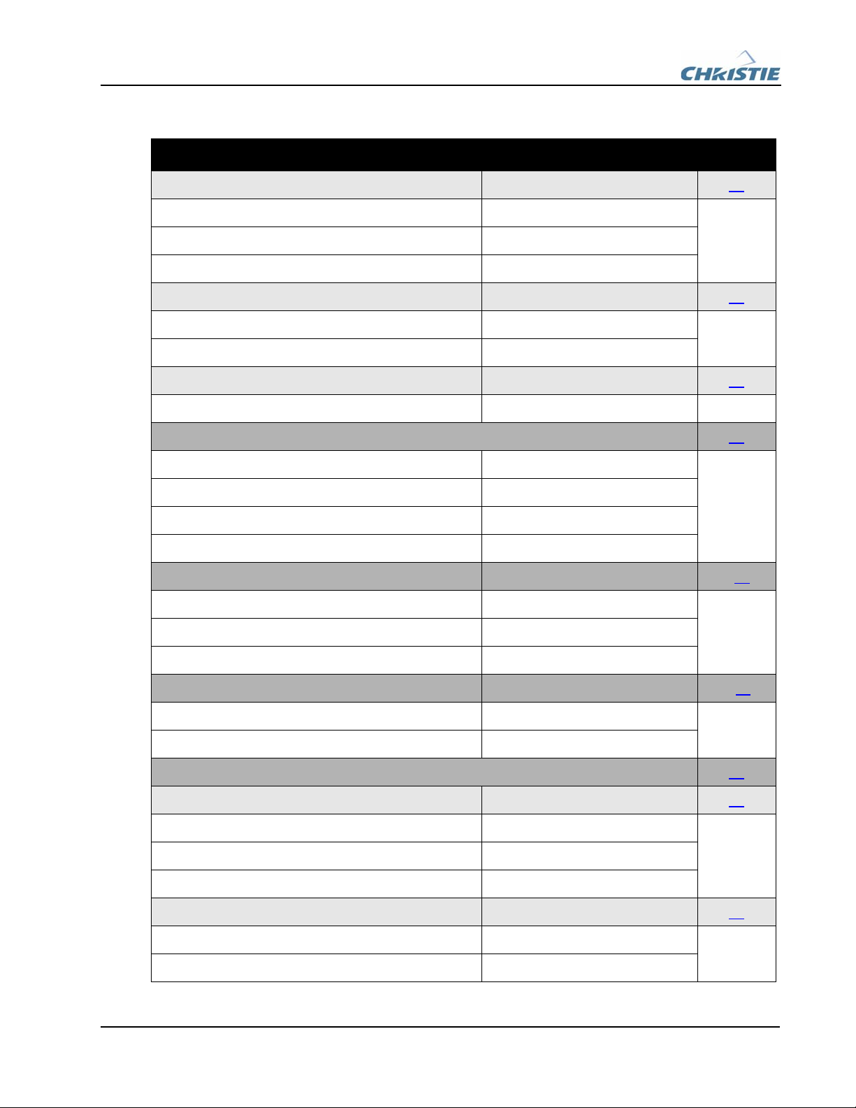
Table 2.1 Index of Parts and Modules
PART/DESCRIPTION PART # PAGE #
Adjuster Plate Assembly M012231 8
• Base Plate M012063
• Nord Lock Washer (x7) Spaenaur #677-320
• Hex Socket Capscrew (x7) Spaenaur #366-774
• Plastic Base Plug M012899
Projector Mount 24
• Yaw Assembly M012230 24
• 3/4” Flat Washer Spaenaur #656-051
• 3/4-16 Hex Nut (x2) Spaenaur #SAN-14
• 3/4” Spherical Washer, Convex Spaenaur #656-256-RC
• 3/4” Spherical Washer, Concave Spaenaur #656-265-RC
• Hex Nut Safety Cap (x2) McMaster Carr #94818A036
• Standard Projector Corner Mount 24
• 3/4-16 Hex Nut (x9) Spaenaur #SAN-14
• 3/4” Spherical Washer, Convex (x6) Spaenaur #656-256-RC
• 3/4” Spherical Washer, Concave (x6) Spaenaur #656-265-RC
• Hex Nut Safety Cap (x9) McMaster Carr #94818A036
MotoBlend Brainbox Bracket M012512 9
• M6 x 12 SHCS (x2) Spaenaur #367-056
MotoBlend Brainbox Model #010-100876-01
M010105 9
• 5/16”-18 Hex Socket Button Head Capscrew (x2) Spaenaur #HX-270-RC
• 5/16”-18 Hex Nut (x2) #012-101081-01
Lens 1.2:1 Fixed #104-111101-01 11
Protective Lens Cap M012898 11
Lens Mount Assembly 1 13
4 of 25 ’Projectors 6 and 7’ Ruggedized Lens Components Installation Manual
020-100055-01 Rev. 1 (05/07)
Lens Support Base Plate 1 M012081 13
• SHCS M10 x 55mm (x2) Spaenaur #367-108
• M10 Washer (x4) Spaenaur #657-012ZP
• M10 Locknut (x2) Spaenaur #166-099
Lens Support Top Plate 1 M012080 14
• M10 Locknut (x2) Spaenaur #166-099
• M10 Washer (x2) Spaenaur #657-012ZP
Lens Support Ring 1 M012079 14
• M4 x 16 SHCS (x2) #012-100623-01
Focus Ring Lock Assembly 15
• Top Locking Bracket M012893
• Bottom Locking Bracket M012894
• M4 x 16mm SHCS (x2) #012-100623-01
• Thumbscrew M013665
Lens Shroud M013643 23
• Clips (x2) M013644
• Case Mounting Screws (x2) Existing Part
• 4-40 Black Phillips Panhead Screws (x2) #12-100278
Lens Mount Bracket M012226 16
• M10 Locknut (x2) Spaenuar #166-099
• M10 Washer (x4) Spaenuar #657-012ZP
Lens Mount Assembly 2 17
Lens Support Base Plate 2 M012084 17
• SHCS M10 x 55mm (x2) Spaenaur #367-108
• M10 Washer (x4) Spaenuar #657-012ZP
• M10 Locknut (x2) Spaenuar #166-099
Lens Support Top Plate 2 M012083 18
• M10 Locknut (x2) Spaenuar #166-099
• M10 Washer (x2) Spaenuar #657-012ZP
Table 2.1 Index of Parts and Modules
PART/DESCRIPTION PART # PAGE #

’Projectors 6 and 7’ Ruggedized Lens Components Installation Manual 5 of 25
020-100055-01 Rev. 1 (05/07)
Lens Support Ring 2 M012082 18
• M4 x 16 SHCS (x2) #012-100623-01
Bumper Bar M012892 19
• Clips (x2) M013337
• M10 Washer (x2) Spaenuar #657-012ZP
• M10 Locknut (x4) Spaenuar #166-099
1.2:1 Extension Plate M012226 16
• M10 Washer (x2) Spaenuar #657-012ZP
• M10 Locknut (x2) Spaenuar #166-099
MotoBlend Frame Assembly M012896 20
• MotoBlend Mounting Brackets (RH and LH) M012090 RH & M012090 LH
• M10 Washer (x4) Spaenuar #657-012ZP
• M10 Locknut (x4) Spaenuar #166-099
• Foam Block M014274
MotoBlend Actuators Model #010-100964-01 21
• 4-40-1/4 Flat Head Stainless Steel Screws (x6) McMaster Carr #394-67843
Filters (No Part Number: Custom Cut to Application) 22
Standoff Filter Mounting Hardware 22
• Flat Washer 1/4 ID x 5/8 O.D. #012-100501-01
• Star Washer Spaenaur #671-064
• 1/4-20 x 0.75 SHCS Spaenaur #HX-15
• Knob - Fine Ribbed Spaenaur #134-086
• Nylon Spacer Spaenaur #606-224
• 6-32 x 3/4 McMaster Carr Setscrew McMaster Carr #92695AI44
Flush Filter Mounting Hardware 22
• Flat Washer 1/4 ID x 5/8 O.D. #012-100501-01
• Star Washer Spaenaur #671-064
• 1/4-20 x 1/2 SHCS Spaenaur #HX-82
• Knob - Fine Ribbed Spaenaur #134-086
Table 2.1 Index of Parts and Modules
PART/DESCRIPTION PART # PAGE #

6 of 25 ’Projectors 6 and 7’ Ruggedized Lens Components Installation Manual
020-100055-01 Rev. 1 (05/07)
• 6-32 x 1/2 McMaster Carr Setscrew McMaster Carr #92695AI10
Table 2.1 Index of Parts and Modules
PART/DESCRIPTION PART # PAGE #

’Projectors 6 and 7’ Ruggedized Lens Components Installation Manual 7 of 25
020-100055-01 Rev. 1 (05/07)
3 SAFETY WARNING AND GUIDELINES
4 INSTALLATION PROCEDURES
NOTES: 1) Read all service instructions. 2) Observe and follow all warnings/instructions marked on
the projector. 3) Service the unit in a clean environment to prevent dust particles from settling on
optical components.
IMPORTANT! Ensure the components and hardware used for Projectors 6 and 7 have the correct
label. Each of the projectors have their own color coded labeling to ensure the correct parts are used.
The labels for Projector 6 are light green and blue for Projector 7.
4.1 RECOMMENDED TOOLS
Ensure the following tools are on-hand when performing the procedures outlined in this document:
• M5/M8 Allen Key
• 3/16” Balldriver
•3mmBalldriver
• 1/2” Wrench
• #1 Phillips Screwdriver
• 17mm Wrench
• Meter Stick, Yard Stick or Measuring Tape
• 1-1/8” Open-end Wrench
WARNING
When powering down the projector, allow the cooling fans to automatically turn OFF
(approximately five minutes) before disconnecting AC and removing covers. Always
unplug the projector before disassembling.
NOTICE
Observe all electrostatic precautions. Use a grounded wrist strap when handling
electronic assemblies.
NOTICE
Use only replacement parts specified by the manufacturer. DO NOT use substitute parts.
NOTICE
A minimum torque of 15-inch/lb. must be applied to each screw.
8 of 25 ’Projectors 6 and 7’ Ruggedized Lens Components Installation Manual
020-100055-01 Rev. 1 (05/07)
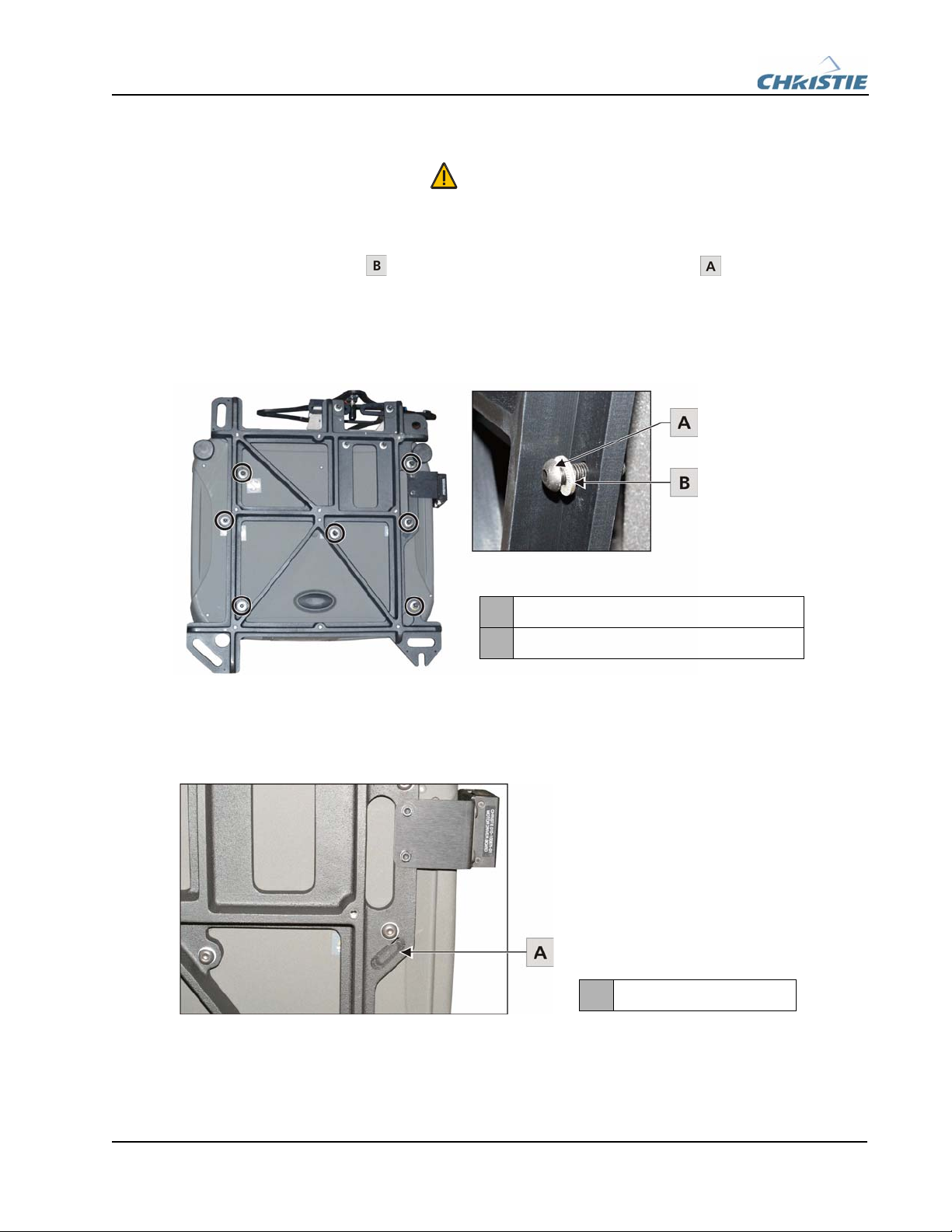
4.2 MOUNT BASE PLATE (M012231) / INSERT BASE PLATE PLUG (M012899)
1. Place a nord lock washer onto each of the seven hex socket capscrews .
2. As one person tilts the projector to expose the underside another person must position the adjuster
plate inline with the designated mounting positions.
3. Use an M8 Allen key to tighten each of the seven hex socket capscrews (Figure 4-1).
Figure 4-1 Base Plate Mounting Positions
4. Snap a base plug into the designated position on the adjuster plate (Figure 4-2). The base plate plug
must be removed when access to the cold mirror adjust is required.
Figure 4-2 Base Plug
WARNING
To avoid possible injuries, a minimum of two people are required to complete this
procedure.
AHex Socket Capscrew (Spaenaur #366-744)
BNord Lock washer (Spaenaur #677-320)
ABase Plug (M012899)

’Projectors 6 and 7’ Ruggedized Lens Components Installation Manual 9 of 25
020-100055-01 Rev. 1 (05/07)
4.3 MOUNT MOTOBLEND BRAINBOX BRACKET (M012512)
1. As one person tilts the projector to expose its underside another person must position the bracket
in-line with the designated mounting positions on the base plate (Figure 4-3).
2. Use an M5 Allen key to tighten the two M5 x 12 socket head capscrews .
Figure 4-3 MotoBlend Brainbox Bracket
4.4 Mount Motoblend Brainbox (#010-100876-01 / M010105)
1. Position the MotoBlend brainbox so it is flush with the outside of the mounting bracket. The
brainbox must be mounted with the DB9 connectors facing the back of the projector.
2. Insert two hex socket button head capscrews through the designated mounting holes.
3. Hand-tighten two hex nuts onto the back of the capscrews.
4. Position a 1/2” wrench onto the hex nut and use a 3/16” balldriver to completely tighten the hex
socket button head capscrew.
Figure 4-4 MotoBlend Brainbox
WARNING
To avoid possible injuries, a minimum of two people are required to complete this
procedure.
AM5 x 12 SHCS (Spaenaur #367-056)
AMotoBlend Brainbox (#010-100876-01)
B5/16”-18 Hex Nut (#012-100553-01)
CHex Socket Button Head Capscrew
5/16”-18 (Spaenaur #HX-270-RC)
10 of 25 ’Projectors 6 and 7’ Ruggedized Lens Components Installation Manual
020-100055-01 Rev. 1 (05/07)
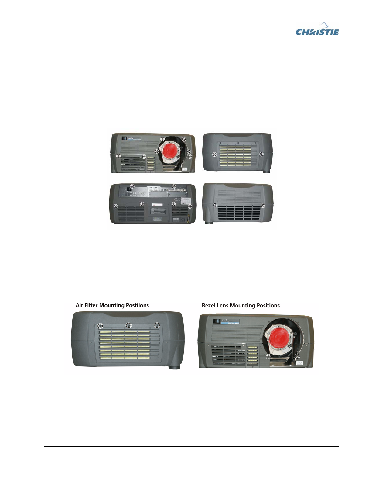
4.5 Remove Top Cover
1. Use a #1 Phillips screwdriver to remove the 17 screws securing the top cover (Figure 4-5).
2. Slowly, lift the top cover up from the lens end to remove.
Figure 4-5 Removing Projector Top Cover
4.6 Remove Side Filter / Bezel Lens Mount
1. Use a #1 Phillips screwdriver to remove the three screws securing the left-side filter door. Note the
orientation of the filter before removing it.
2. Use a #1 Phillips screwdriver to remove the two screws securing the bezel mount to the bottom
cover.
Figure 4-6 Air Filter / Bezel Lens Mounting Positions
NOTICE
The front IR sensor PCB is located in the front left corner and can be damaged if it is hit
when the cover is removed.
This manual suits for next models
1
Table of contents
Other Christie Lens manuals

Popular Lens manuals by other brands


Tamron
Tamron SP 70-300mm F/4-56 Di VC USD Brochure & specs

Panasonic
Panasonic VW-W4907 operating instructions

Navitar
Navitar 1-51332 Dimensional drawing

Leica
Leica APO-SUMMICRON-SL 1:2/50 ASPH. instructions

Sony
Sony LKRL-Z200 Series Product information

Cosina
Cosina Voigtländer SUPER NOKTON 29mm F0.8... instruction manual
 4.5/55 Operation manual")


