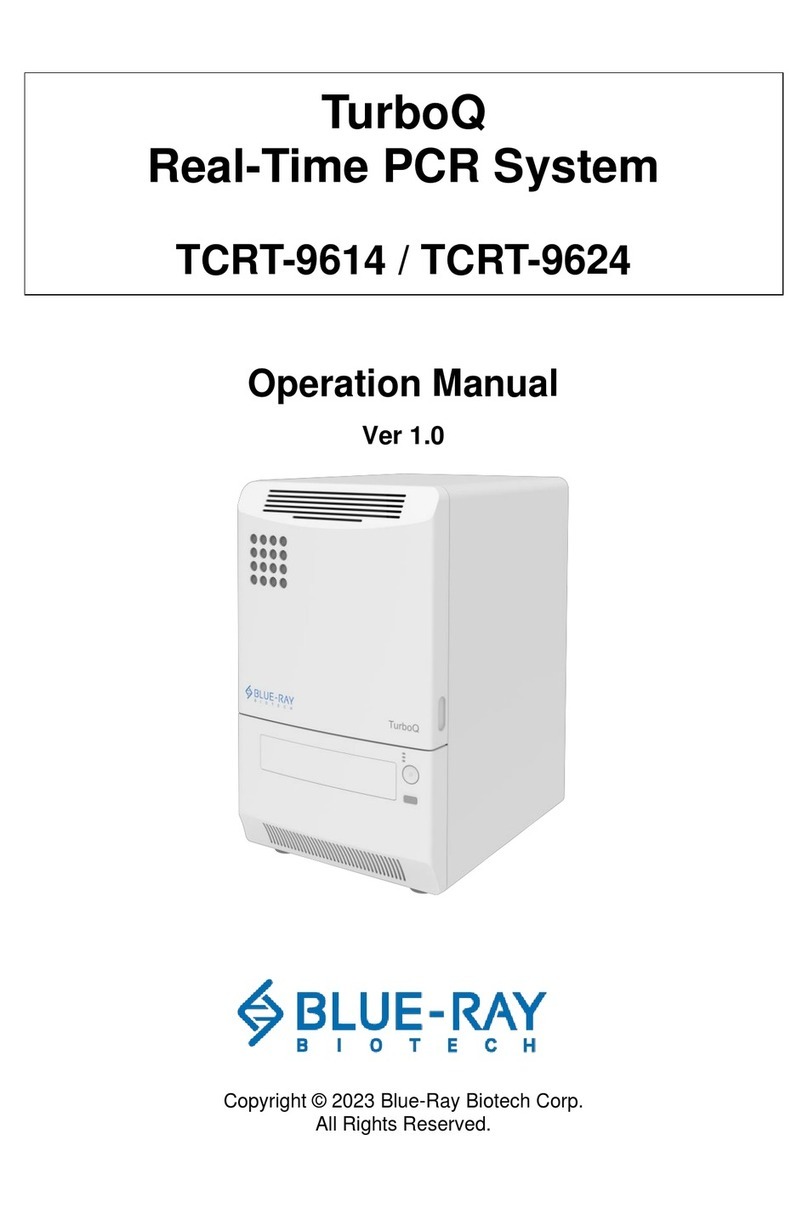
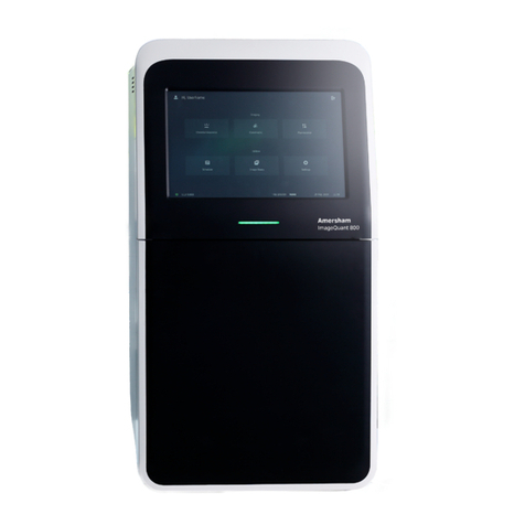
ChromaCon Contichrom CUBE 30 User guide

Contichrom System Manual
page 1of 80
Contichrom® System Manual v2.6 / 07/2017 © ChromaCon AG www.chromacon.com
Contichrom® CUBE 30/100 (FPLC)
Contichrom® CUBE Combined 30/100 (FPLC)
Contichrom® HPLC 30/100
System Manual

Contichrom System Manual
page 2of 80
Contichrom® System Manual v2.6 / 07/2017 © ChromaCon AG www.chromacon.com
Content (to access a chapter click on the entry)
Safety Symbols / Symboles de Sécurité ................................................................................ 5
Safety information .............................................................................................................. 5
Regulatory information....................................................................................................... 6
Introduction to The Contichrom System............................................................................... 6
Introduction................................................................................................................................ 6
Contichrom System Illustration.................................................................................................... 8
1. The Contichrom system.............................................................................................. 9
1.1. General Instrument Overview............................................................................................ 9
1.2. Overview of wetted system components ..........................................................................11
1.3. Liquid fluid path ...............................................................................................................12
1.3.1. Overview...........................................................................................................................................12
1.3.2. Twin column Fluid Paths ...................................................................................................................13
1.3.3. Adding and removing Tubes .............................................................................................................14
1.3.4. Connecting CUBE and CUBE+ modules .............................................................................................14
1.4. Instrument Components...................................................................................................15
1.4.1. Pumps ...............................................................................................................................................15
1.4.2. Back Pressure Regulators..................................................................................................................16
1.4.3. Valves................................................................................................................................................17
1.4.4. Detectors ..........................................................................................................................................19
1.4.5. Fraction Collector..............................................................................................................................19
2. Preparing the Contichrom instrument .......................................................................20
2.1. Starting the System ..........................................................................................................20
2.2. Launching ChromIQ and Logging in ...................................................................................20
2.1. Buffer/Solvent preparation ..............................................................................................22
2.2. Buffer tank assignment and tank levels.............................................................................23
2.3. Preparing the fluid outlets ................................................................................................26
2.4. Filling the Pump Seal wash ...............................................................................................27
2.5. Filling the pumps..............................................................................................................28
2.6. Standard methods for priming pumps...............................................................................29
Method “LOAD_Buffers_5-positions.mth”.......................................................................................................29
Method “LOAD_Buffers_7-positions.mth”.......................................................................................................30
Methods to fill one Inlet of a pump only ..........................................................................................................30
2.7. Method for capillary filling and system storage .................................................................31
Method Fill_Capillaries_with_Buffer_A.mth ....................................................................................................31
Method Valves_Storage_Position.mth.............................................................................................................31

Contichrom System Manual
page 3of 80
Contichrom® System Manual v2.6 / 07/2017 © ChromaCon AG www.chromacon.com
2.8. Methods for UV-sensors...................................................................................................31
Method UV AutoZero.mth................................................................................................................................31
Method Backflush_Detectors.mth ...................................................................................................................31
2.9. Other Methods.................................................................................................................32
Method Pause.mth ...........................................................................................................................................32
Frac_Home.mth ................................................................................................................................................32
2.10. Standard Procedures.....................................................................................................32
Load_Buffers.PRC .............................................................................................................................................32
Cleaning.PRC.....................................................................................................................................................32
2.11. Creating methods and performing runs .........................................................................33
2.12. Preparing and mounting the columns ............................................................................33
2.13. Mounting the pH flow cell and electrode .......................................................................34
2.14. Preparing The fraction collector.....................................................................................35
2.15. Operation in cold cabinet or cold room..........................................................................36
3. Operating the Contichrom system .............................................................................36
3.1. Recommended Column Sizes................................................................................................36
3.1. Preparing a procedure to be run...........................................................................................37
3.2. Procedure for Loading buffers ..............................................................................................38
3.3. Starting a run.......................................................................................................................38
3.4. Managing a run....................................................................................................................39
Refilling Buffers during a run ............................................................................................................................40
3.5. Monitoring a Run.................................................................................................................41
3.6. Programming Methods.....................................................................................................43
3.7. Evaluating a run ...............................................................................................................43
3.8. Log Book ..........................................................................................................................43
4. Cleaning the system..................................................................................................44
4.1. Simple Cleaning................................................................................................................44
4.2. Thorough Cleaning ...........................................................................................................44
5. Storing the system ....................................................................................................46
5.1. Storing the pH electrode...................................................................................................47
6. Maintenance ............................................................................................................47
6.1. Recommended Maintenance Intervals..............................................................................48
6.2. Calibrating the pH sensor..................................................................................................48
6.3. Pump Maintenance ..........................................................................................................50
Pump seal wash Solution Replacement............................................................................................................50
Pump Head Maintenance .................................................................................................................................50
Cleaning the Pump Head Assembly ..................................................................................................................51

Contichrom System Manual
page 4of 80
Contichrom® System Manual v2.6 / 07/2017 © ChromaCon AG www.chromacon.com
Replacing the Pump Head.................................................................................................................................52
Piston Seals.......................................................................................................................................................52
Replacing the Seals ...........................................................................................................................................53
Pistons ..............................................................................................................................................................54
Check Valve Cleaning and Replacement...........................................................................................................55
Seal Wash Check Valve Replacement ...............................................................................................................56
6.4. Valve maintenance...........................................................................................................57
Cleaning and Rotor Replacement .....................................................................................................................58
6.5. Replacing Tubing Connections ..........................................................................................59
6.6. Detector maintenance......................................................................................................61
6.7. ChromIQ Software Installation..........................................................................................61
6.8. ChromIQ Software Update................................................................................................61
7. Troubleshooting .......................................................................................................62
7.1. General TroubleShooting Procedure.....................................................................................62
7.2. Detailed Troubleshooting Procedure ....................................................................................62
7.3. Disposal of the System .....................................................................................................70
7.4. System Qualification Tests................................................................................................70
8. Appendix ..................................................................................................................71
Appendix A - Technical Specifications.........................................................................................71
Appendix B - List of wetted parts ...............................................................................................75
Appendix C –Chemical resistance Guide .....................................................................................75
Appendix D - Room Requirement for operation and storage .......................................................77
Appendix E - List of Spare Parts..................................................................................................78
Appendix F - Manual Control using System Center.......................................................................79
©copyright 2017 ChromaCon AG. All ChromaCon® processes are patented. ChromaCon®, Contichrom®,
CaptureSMB®, N-Rich®, AutomAb®, ChromIQ® are all registered trademarks of ChromaCon AG. The absence of a
product or service name or logo from this list does not constitute a waiver of ChromaCon AG's trademark or
other intellectual property rights concerning that name or logo.

Contichrom System Manual
page 5of 80
Contichrom® System Manual v2.6 / 07/2017 © ChromaCon AG www.chromacon.com
SAFETY SYMBOLS / SYMBOLES DE SÉCURITÉ
SAFETY INFORMATION
This manual contains WARNINGS and NOTICES concerning safety. These are defined below:
WARNING:
A WARNING is represented by the following symbol and warning information:
WARNING: Warning information
WARNING indicates a hazardous situation which, if not avoided, could result in harm to the system operator. It
needs to be ensured that the hazardous situation is resolved before proceeding.
NOTICE:
A NOTICE is represented by the following symbol and warning information:
NOTICE: Notice information
NOTICE indicates a situation which, if not avoided, could result in damage to the instrument. It needs to be
ensured that the situation is resolved before proceeding.

Contichrom System Manual
page 6of 80
Contichrom® System Manual v2.6 / 07/2017 © ChromaCon AG www.chromacon.com
REGULATORY INFORMATION
Class A: EMC Registration is done on this equipment for business use only (Class A). Product seller and user
should notice that this equipment is not for household use.
INTRODUCTION TO THE CONTICHROM SYSTEM
INTRODUCTION
Contichrom is a modular laboratory scale chromatography platform designed for operation of single column and
two column chromatography processes. The Contichrom platform is offered in different system configurations as
shown in the table below. This System Manual is not applicable to the Contichrom Discovery system.
Contichrom Module Overview:
CUBE: A module with 36 mL/min pumps, valves and detector system
CUBE+: A module with 36 mL/min pumps, complementary with the CUBE module
CUBE 100: A module with 100 mL/min pumps, valves and detector system
CUBE+ 100: A module with 100 mL/min pumps, complementary with the CUBE 100 module
All modules are available with a pressure rating of 50 bar for Fast Protein Liquid Chromatography (FPLC) and with
a pressure rating of 100 bar for High Performance Liquid Chromatography (HPLC).
The Contichrom system platform comprises the following components:
Contichrom system according to the table below
Laptop with the ChromIQ software installed
Optional Fraction Collector
Auxiliaries

Contichrom System Manual
page 7of 80
Contichrom® System Manual v2.6 / 07/2017 © ChromaCon AG www.chromacon.com
Contichrom Systems Overview:
Contichrom
CUBE 30
Contichrom
CUBE 100
Contichrom
CUBE
Combined 30
Contichrom
CUBE
Combined
100
Contichrom
HPLC 30
Contichrom
HPLC 100
CUBE
module
CUBE
CUBE 100
CUBE
CUBE 100
CUBE
CUBE 100
CUBE+
module
n.a.
n.a.
CUBE+
CUBE+ 100
CUBE+
CUBE+ 100
Max. flow
[mL/min]
36
100
36
100
36
100
Max.
pressure
[bar]
50
50
50
50
100
100
Tubing i.D.
[mm],
pressure side
0.75
1.00
0.75
1.00
0.75
1.00
The Contichrom systems are available with maximal flow rates of 36 mL/min and 100 mL/min. The Contichrom
CUBE system is a stand-alone instrument, consisting of the Contichrom CUBE module and being capable of
running multiple chromatographic processes. The CUBE+ upgrade module, in combination with the Contichrom
CUBE module, forms the “Contichrom CUBE Combined” configuration that unlocks the full range of twin-column
chromatography processes. “Contichrom HPLC” is a Contichrom CUBE Combined configuration with 100 bar
pressure rating. The process capabilities for the individual configurations are shown in the table below:
Process
Capabilities
Contichrom Systems
Contichrom
CUBE 30
Contichrom
CUBE 100
Contichrom
CUBE
Combined 30
Contichrom
CUBE
Combined
100
Contichrom
HPLC 30
Contichrom
HPLC 100
Batch (single
column)
Integrated
Batch
(isocratic)
Integrated
Batch
(lin.gradient)
2C-PCC
MCSGP
N-Rich
Columns with the same resin or different resins can be used.
Briefly, the different twin-column processes serve the following purposes:
-Integrated Batch chromatography combines two chromatography steps using different resins and
automates the purification. The eluate from the first column is directly loaded on the e second column
whereby inline dilution can be used.
-2C-PCC (CaptureSMB) increases throughput and decreases resin consumption in affinity capture
applications compared to single column batch capture chromatography.

Contichrom System Manual
page 8of 80
Contichrom® System Manual v2.6 / 07/2017 © ChromaCon AG www.chromacon.com
-MCSGP is designed for difficult purifications where overlapping of impurities and the target molecule
significantly lower the product pool purity. MCSGP produces target components with high yield and high
purity at the same time.
-N-Rich isolates product-related impurities for characterization purposes. The process enriches the side-
components while simultaneously depleting interfering main compounds, potentially saving dozens of
HPLC runs.
CONTICHROM SYSTEM ILLUSTRATION
The following illustration is representative of Contichrom CUBE Combined 30/100 system and of Contichrom
HPLC 30/100 system:
pH electrode Contichrom CUBE
CUBE+ upgrade module Fraction collector
Computer
USB and LAN
connection to
computer
Contichrom CUBE

Contichrom System Manual
page 9of 80
Contichrom® System Manual v2.6 / 07/2017 © ChromaCon AG www.chromacon.com
1. THE CONTICHROM SYSTEM
1.1. GENERAL INSTRUMENT OVERVIEW
The Contichrom platform comprises the following main components:
Contichrom CUBE module (30/100), present in Contichrom CUBE 30/100 systems, Contichrom CUBE
Combined 30/100 systems and Contichrom HPLC 30/100 systems
CUBE+ upgrade module (30/100), present in Contichrom CUBE Combined 30/100 systems and in the
Contichrom HPLC 30/100 systems
The CUBE+ upgrade module, in combination with the CUBE module, forms the “Contichrom CUBE Combined
30/100” systems or the Contichrom HPLC 30/100 systems, respectively.
UV (280, 300 nm)
and conductivity cells
System/gradient pumps
Gradient pumps
Outlet/column valves
Inlet/column valves
Buffer selection valve
Drain valve
Manual purge valves
Buffer selection valve
Twin columns with
column holders
Pressu re
sensor
Pressu re
sensor
Contichrom CUBE
CUBE + module
Contichrom CUBE combined
Front view of the Contichrom CUBE Combined

Contichrom System Manual
page 10 of 80
Contichrom® System Manual v2.6 / 07/2017 © ChromaCon AG www.chromacon.com
Connector for fraction
collector
Connector
for pH electrode
Connector for link to
computer
Connector for link to
CUBE+ module
Power switch
Tubing
guides
USB Connector for link to
computer
Socket for
Power cable
Side and back view of the CUBE module (top)
Connector for link to
CUBE+ module
Power switch
Socket for
Power cable
Side and back view of the CUBE+ module (bottom)

Contichrom System Manual
page 11 of 80
Contichrom® System Manual v2.6 / 07/2017 © ChromaCon AG www.chromacon.com
1.2. OVERVIEW OF WETTED SYSTEM COMPONENTS
The following illustration shows the system components that are in contact with liquid during operation of the
the Contichrom system. The picture shows a “Contichrom CUBE Combined system” but is equally valid for the
“Contichrom HPLC” systems.
P3
V2-B
VP3
MDV-3
PT-2
PT-1A
Contichrom CUBE
CUBE + module
Contichrom CUBE combined
V1-B
V1-A
V2-A
P2
MDV-2
VP2
PT-3
V6
V5
PT-1B
P1B
P1A
UV1 UV2
MDV-1A MDV-1B
Description
Description
CUBE + module
P3
Pump 3
P1A
Pump 1 A, channel A of gradient with P1B
MDV-3
Manual drain valve for P3
MDV-1A
Manual drain valve for P1A
PT-3
Pressure sensor for P3
PT-1A
Pressure sensor for P1A
VP3
Buffer selection valve for P3
P1B
Pump 1 B, channel B of gradient with P1A
V6
Automatic drain valve for P2 and P3
MDV-1B
Manual drain valve for P1B
PT-1B
Pressure sensor for P1B
V1A
Inlet column valve for column position 1
V5
Automatic drain valve for P1A and P1B
V1B
Outlet column valve for column position 1
V2A
Inlet column valve for column position 2
CUBE module
V2B
Outlet column valve for column position 2
P2
Pump 2
MDV-2
Manual drain valve for P2
UV1
Flow cell for fixed dual wavelength detector, conductivity,
temperature
PT-2
Pressure sensor for P2
UV2
Flow cell for fixed dual wavelength detector, conductivity,
temperature
VP2
Buffer selection valve for P2
WARNING: Contichrom equipment must not be used with human contagious materials and/or
radioactive materials.

Contichrom System Manual
page 12 of 80
Contichrom® System Manual v2.6 / 07/2017 © ChromaCon AG www.chromacon.com
1.3. LIQUID FLUID PATH
1.3.1. OVERVIEW
The illustrations below show the flow sheets of the Contichrom CUBE Combined system and of the CUBE system,
respectively. The flow sheet of the Contichrom HPLC is identical to the flow sheet of the Contichrom CUBE
Combined system.
In the CUBE module can utilize up to 16 different buffers (Pumps 2 and 3 each equipped with an 8-way buffer
selection valve). In the CUBE+ module each pump is connected to one buffer, adding 2 more buffers for a total of
18 buffers that can be potentially used in a Contichrom CUBE Combined / Contichrom HPLC system.
The Contichrom systems are provided with a fully assembled fluid path. By default, the tubing on the low
pressure side (before the pumps) consists of tubing with 1/8 inch outer diameter and 1.55 mm inner diameter
(CUBE / CUBE Combined 30) and 2.0 mm inner diameter (CUBE / CUBE Combined 100), respectively.
The tubing on the high pressure side consists of capillaries with 1/16 inch outer diameter and 0.75 mm inner
diameter (CUBE / CUBE Combined 30) and 1.0 mm inner diameter (CUBE / CUBE Combined 100), respectively.
The drain tubing and the pump seal wash tubing is of 8 inch outer diameter and 1.55 mm inner diameter (CUBE /
CUBE Combined 30) and 2.0 mm inner diameter (CUBE / CUBE Combined 100), respectively.
Flow Sheet of the Contichrom CUBE Combined 30/100 systems (pump seal wash lines not shown). The flow
sheet for the Contichrom HPLC 30/100 systems are identical:

Contichrom System Manual
page 13 of 80
Contichrom® System Manual v2.6 / 07/2017 © ChromaCon AG www.chromacon.com
Flow Sheet of the Contichrom CUBE 30/100 systems (pump seal wash lines not shown):
WARNING: Be aware that protruding capillaries and tubes may trap parts of the body or clothing
causing abrasion and/or injury.
1.3.2. TWIN COLUMN FLUID PATHS
The Contichrom systems have been designed to support both single column batch chromatography and
chromatography processes with two columns.
The fluid path allows running the columns in single column mode or in interconnected mode. When run in
interconnected mode either column can be selected to be the most upstream one. Detectors are located at the
outlet of each column.
In combination with the Contichrom CUBE 30/100 module, the CUBE+ modules add additional gradient
capabilities and inline dilution capabilities. A linear gradient can run on one of the columns and the eluate can be
diluted inline before being loaded onto a second column.

Contichrom System Manual
page 14 of 80
Contichrom® System Manual v2.6 / 07/2017 © ChromaCon AG www.chromacon.com
The following schematic illustrates the fluid paths for Contichrom CUBE 30/100 and Contichrom CUBE Combined
30/100 systems// Contichrom HPLC 30/100 systems used in the different single and multicolumn processes.
1 2 1 22
11 2 1 2
Contichrom CUBE Combined 30/100, Contichrom HPLC 30/100
Contichrom CUBE 30/100
1.3.3. ADDING AND REMOVING TUBES
The Contichrom systems are either delivered with a pre-mounted set of tubing or the tubing is installed by
service personnel.
NOTICE: The user is strongly advised not to modify the flow sheet of the Contichrom system
on the high pressure side, apart from the modification that is necessary to connect the upper
and the lower system modules. The ChromIQ operating software is based on the predefined
flow sheet. Modifying the flow sheet may lead to dead-ending of pumps when using the
process wizards, which may lead to column damage. It is recommended to contact ChromaCon service personnel
before doing major changes of the flow path.
Tubing with 1/8 inch outer diameter and the colored buffer selection valve fittings may be added to increase the
number of selectable buffers on the low pressure side at the buffer selection valves. See chapter “buffer
selection valves”.
1.3.4. CONNECTING CUBE AND CUBE+ MODULES
Contichrom CUBE Combined 30/100 systems and Contichrom HPLC 30/100 systems comprise of an upper
module (CUBE module) and a lower module (CUBE+ module). For mounting the tubing that connects the two
modules please refer to the instructions “Contichrom installation guide” and “CUBE/CUBE+ connection guide”
provided in separate documents.

Contichrom System Manual
page 15 of 80
Contichrom® System Manual v2.6 / 07/2017 © ChromaCon AG www.chromacon.com
1.4. INSTRUMENT COMPONENTS
1.4.1. PUMPS
The Contichrom CUBE 30/100 modules are provided with two high precision double-head pumps (P2 and P3),
each equipped with a buffer selection valve on the suction side (VP2, VP3). In the Contichrom CUBE 30/100
system, P2 and P3 are referred to as PA and PB, respectively, by the ChromIQ operating software. The pumps can
operate independently in isocratic mode or may be joined to run a gradient. By default, P3 (PB) is used as the
feed pump.
The Contichrom CUBE Combined 30/100 systems and the Contichrom HPLC 30/100 systems feature two
additional pumps P1A, P1B that are joined on the high pressure side to provide additional linear gradient
capabilities.
The flow from each pump passes through a manual purge valve that is suited for manual filling and purging of the
pumps. Afterwards the fluids pass through the pressure sensors. The setup of pump, manual purge valves and
pressure sensors is shown in the illustration below.
The pumps include a self-flush feature of the pump heads. The self-flushing provides continuous washing of the
piston surface without the inconvenience of a manual flush or gravity feed arrangement. The self-flushing pump
head uses a self-flush seal and secondary set of check valves to create a continuous and positive flow in the area
behind the high-pressure pump seal.
It is recommended that the self flush feature be used to improve seal life in a number of applications. In
particular, (as stated above) if pumping buffers, acids/bases or any inorganic solution near saturation, the pump
should utilize the self flush feature. With every piston stroke, an extremely thin film of solution is pulled back
past the seal. If this zone is dry (without use of self flush) then crystals will form with continuous operation,
which will ultimately damage the seal.
20% IPA/water mix or 30% Ethanol/water mix are good choices for the flush solution.
A schematic of the fluid connections of the seal wash of Contichrom CUBE Combined 30/100 systems are
provided further below. The fluid connections of the Contichrom HPLC 30/100 systems are the same.
NOTICE: It is strongly recommended to ensure that the self-flushing feature is working
properly. The flushing solution washes away any buffer salts that have precipitated onto the

Contichrom System Manual
page 16 of 80
Contichrom® System Manual v2.6 / 07/2017 © ChromaCon AG www.chromacon.com
piston. If not removed, these precipitates can abrade the high-pressure seal and cause premature seal failure,
leakage, and can possibly damage the pump.
Seal
wash
liquid
P1B
P1A
Seal
wash
liquid
P2 P3
CUBE
module
CUBE+
module
1.4.2. BACK PRESSURE REGULATORS
Back pressure regulators (40 psi, 2.75 bar) are mounted at all system outlets. The back pressure regulators
suppress bubble formation in the system, thus increasing the accuracy. Moreover back pressure regulators
prevent buffers leakage from the system due to hydrostatic pressure. The back pressure regulators are mounted
at the following positions (also refer to flow sheet in chapter 1.3):
1. Drain outlet (at drain manifold on the drain line)
2. On the line originating from the joined outlets of V1B-6 and V2B-6 (also referred to as “W-outlet” or
“strip outlet)
3. On the line originating from the joined outlets of V1B-3 and V2B-3 (also referred to as “P-outlet” or
“product outlet”) after the pH electrode.
4. On the line originating from the joined outlets of V1B-1 and V2B-1 (also referred to as “S-outlet” or
“strip outlet)
NOTICE: Make sure that the pH flow cell is connected such that outlet of the flow cell is open
to the atmosphere without a back pressure regulator. The back pressure regulator must be
located on the inlet side of the pH flow cell since the pH electrode is susceptible against high
pressures
NOTICE: It is not recommended to use columns with a pre column pressure limit of 72 psi (5
bar) pressures when the back pressure regulators are mounted. For these columns, the
backpressure regulators 2.-4. (see above) must be removed. The backpressure regulator on
the drain outlet 1. (see above) must never be removed!

Contichrom System Manual
page 17 of 80
Contichrom® System Manual v2.6 / 07/2017 © ChromaCon AG www.chromacon.com
One pressure sensor is mounted at each pump after the manual drain valve. The pressure sensors record the pre-
column pressure.
1.4.3. VALVES
Drain valves
The modules of the Contichrom system are equipped with the following automatic drain valves:
V6 for CUBE 30/100 module
V6 for the CUBE 30/100 module of the Contichrom CUBE Combined 30/100 systems and of the
Contichrom HPLC 30/100 systems, respectively and
V5 for the CUBE + 30/100 modules of the Contichrom CUBE Combined 30/100 systems and Contichrom
HPLC 30/100 systems.
These valves are used for rapidly filling the buffer lines and the pumps with new buffers at high flow
rates. V6 is attributed to pumps P2 and P3 (PA and PB in CUBE 30/100 module) while V5 is attributed to
P1A/B of the CUBE+ 30/100 module. The streams from P1A and P1B are united before entering V5.
The drain valves have two positions:
1. Position 1, “to system”: the drain valves connect the pumps with the column valves
2. Position 2. “drain”: the drain valves connect the pumps with the drain outlet
Buffer selection valves
The pumps P2 and P3 of the Contichrom CUBE Combined 30/100 system and Contichrom HPLC 30/100 system
(pumps PA and PB of the Contichrom CUBE 30/100 system) are equipped with automatic buffer selection valves
on the suction side. Each buffer selection valve can select among 8 different buffer/feed solutions (see
illustration below). By default, the feed stock solution containing the product to be purified is connected to VP3,
inlet 2. The center position of the buffer selection valves leads to the pump. Buffer positions that are not in use
should be closed using plugs. Tubing with 1/8 inch outer diameter and the colored buffer selection valve fittings
may be added to increase the number of selectable buffers on the low pressure side at the buffer selection
valves.
Column valves
A Contichrom system includes four column valves, one inlet column valve and one outlet column valve per
column, see illustration below. The column valves are multi-position valves, connected as follows.
1. the center positions of the column inlet valves are connected to the column inlets
2. the center positions of the column outlet valves are connected to the outlets of the respective detector flow
cells (denoted by “UV1” and “UV2” in the illustration below.

Contichrom System Manual
page 18 of 80
Contichrom® System Manual v2.6 / 07/2017 © ChromaCon AG www.chromacon.com
V1A is the inlet column valve of column 1, V1B is the outlet column valve of column 1.
V2A is the inlet column valve of column 2, V2B is the outlet column valve of column2.
The remaining valve inlets and outlets are connected as follows:
Example Inlet/outlet map for Contichrom CUBE Combined 30/100 and Contichrom HPLC 30/100
Position
V1A
V1B
V2A
V2B
1
From P1
Strip outlet
From P1
Strip outlet
2
Internal recycling
from column 2,
inline dilution by P2
Internal recycling to
column 2
Internal recycling
from column 1,
inline dilution by P2
Internal recycling to
column 1
3
From P3
Product outlet
From P3
Product outlet
4
Internal recycling
from column 2,
inline dilution by P2
Internal recycling to
column 2
Internal recycling
from column 1,
inline dilution by P2
Internal recycling to
column 1
5
From P2
CIP outlet
From P2
CIP outlet
6
Inlet plugged/ store
position
Waste outlet
Inlet plugged/ store
position
Waste outlet

Contichrom System Manual
page 19 of 80
Contichrom® System Manual v2.6 / 07/2017 © ChromaCon AG www.chromacon.com
1.4.4. DETECTORS
The Contichrom system contains a detector system measuring two fixed wavelengths at the outlet of each
column. In its standard layout, the wavelengths are 280 nm and 300 nm. Moreover, the detector system
measures the conductivity at the outlet of each column and the fluid temperature at the outlet of column 1. In
flow cell 1 (left-hand side when facing CUBE) UV, conductivity and temperature are measured, in flow cell 2
(right-hand side when facing CUBE) UV and conductivity are measured. A separate flow cell is provided for the pH
electrode. Refer to chapter 2.13 for mounting the pH electrode.
The detector system is pre-calibrated. However it is recommended to calibrate the pH before the first run.
1.4.5. FRACTION COLLECTOR
The Fraction collectors R1 and R2 are optional accessories for the Contichrom system (see picture below). The
Fraction collectors can carry different rack types including 50 mL centrifuge tube, 15 mL centrifuge tubes, HPLC
vials and 96-well plates. The R2 fraction collector can carry twice the number of racks and therefore has twice
the capacity of the R1 fraction collector. The rack type is set in the ChromIQ operating software. Fractionation
can be initiated based on time, volume, column volume and can be triggered through a number of different
signals such as UV and conductivity.
By default, the fraction collector is connected to the product outlet. When installing the fraction collector make
sure that the secondary drain of the fraction collector routes liquid from the drip tray of the fraction collector to
a safe collection point.
Additional information on the fraction collector is provided in the R1/R2 fraction collector manual.
Information on the programming of the fraction collector is provided in the ChromIQ software manual.
R1 fraction collector
R2 fraction collector
WARNING: The drain outlet and the drip tray fluid outlet of the fraction collector must be routed
to a waste container in order to avoid spillage. A hazardous situation may arise when liquids that
are flammable or conductive are overflowing and get in contact with sources of ignition or
electricity. Make sure that the secondary drain of the fraction collector routes liquid from the drip
tray of the fraction collector to a safe collection point.

Contichrom System Manual
page 20 of 80
Contichrom® System Manual v2.6 / 07/2017 © ChromaCon AG www.chromacon.com
2. PREPARING THE CONTICHROM INSTRUMENT
2.1. STARTING THE SYSTEM
The Contichrom CUBE 30/100 system is switched on by plugging the power cable in and pressing the power
switch. Contichrom CUBE Combined 30/100 systems and Contichrom HPLC 30/100 systems are switched on by
plugging the power cables of the CUBE and the CUBE+ modules and by pressing their power switches.
The fraction collector is switched on by plugging in the power cable and by pressing the power symbol on its
touchpad.
Once the power switches are on, acoustic signals will confirm that internal communications of the instrument
have been launched.
WARNING: Only trained operators should set-up and operate the Contichrom system to avoid
human injury.
2.2. LAUNCHING CHROMIQ AND LOGGING IN
Contichrom instruments are operated using the ChromIQ operating software. The software is started using a
desktop icon or the start menu of the control computer. After logging onto the control computer that is
connected to the instrument, the ChromIQ software can be started by clicking on the ChromIQ icon on the
desktop or selecting the software icon from the Windows start menu.
ChromIQ icon
As the software is being loaded, a window will appear indicating the software version and the software
establishes the connection to the instrument and checks the availability of all hardware components.
When the software has finished loading, a login page appears where you can enter your user name and password
at the prompt.
This manual suits for next models
5
Table of contents
