Chromalox SRL User manual

Installation Instructions
Industrial Heating Cable
Products
PJ438-26
161-057884-010
May, 2021

Table of Contents
Important Safeguards and Warnings..................................................................................... 3
System Components............................................................................................................... 4
Chromalox Cable Types.......................................................................................................... 5
General Information ................................................................................................................ 6
Use of Manual ..................................................................................................................... 6
Storage................................................................................................................................ 6
Important Installation Notes ................................................................................................ 6
Installation................................................................................................................................ 7
Pre-Installation Guidelines .................................................................................................. 7
Installation Guide: Single Run of Cable............................................................................... 8
Installation Guide: Multiple Cable Runs .............................................................................. 9
Installation on Fire Protection Systems............................................................................. 10
Other Installation Considerations...................................................................................... 11
Typical Installation Details.................................................................................................... 12
Wiring...................................................................................................................................... 16
Heating Cable Components ................................................................................................. 18
Connection Kits................................................................................................................. 18
Accessories ....................................................................................................................... 22
Control Systems .................................................................................................................... 23
Controllers ......................................................................................................................... 26
Thermal Insulation................................................................................................................. 28
Commission Testing.............................................................................................................. 28
Specifications ........................................................................................................................ 29
Troubleshooting..................................................................................................................... 31
Locating Faults.................................................................................................................. 32
Insulation Resistance (Megger) Test.................................................................................. 34
Stabilized Current Test ...................................................................................................... 34
End of Current Voltage Test............................................................................................... 34
Installation and Maintenance Log........................................................................................ 35

3
Important Safeguards and Warnings
FIRE HAZARD. Failure to follow these guidelines
could result in property damage or personal injury.
• Disconnect all power sources before installing or
servicing heating cable. Failure to do so could
result in personal injury or property damage.
• Heating cable must be installed by a qualified
person in accordance with the National Electri-
cal Code, NFPA 70.
• Each heating cable branch circuit must be effec-
tively grounded in accordance with the National
Electrical Code to eliminate shock hazard.
• Never attempt to use damaged heating cables or
connection kits. If cable damage is observed, ei-
ther replace the complete heating cable, or cut
out the damaged section and replace using the
proper splice connection kit. Do not attempt to
repair damaged heating cable.
• Never energize the cable when it is coiled or on a
reel. Test only when it is laid out straight.
• Handle coils and reels utilizing equipment de-
signed for that purpose.
• Do not drop coils or reels, especially from trans-
porting equipment.
• Lift or handle reels so that the lifting/handling
device does not come in contact with the cable
or it’s protective covering. Coils should be placed
on a skid.
• Handle reels so that the deterioration or physical
damage of cable is prevented.
• Do not install heating cable on equipment which
could become hotter than the heating cable’s
maximum exposure temperature.
• Do not install heating cable in an area or on
equipment which contains potentially corrosive
materials without having a suitable protective
jacket on the cable. Observe all published speci-
fications.
• Do not expose cables to temperatures above
their specified maximums. Do not run cables lon-
ger than specified maximum circuit lengths. See
tables provided in this installation manual for de-
tails.
• Never use tie-wire or pipe straps to secure Self-
regulating or Constant Wattage heating cables,
as this may damage the cable.
• Keep bus wires separated to avoid shorting the
cable.
• Keep cable ends and connection kits dry before
and during installation.
• Be careful not to break bus wire strands when
preparing the cable, as damaged bus wires can
overheat and short.
• The presence of heating devices must be evident
by the posting of caution signs or markings at ap-
propriate locations and/or at frequent intervals
along the circuit.
• Users should install adequate controls and safe-
ty devices with their electric heating equipment.
Where the consequences of failure may be se-
vere, back-up controls are essential. Although
the safety of the installation is responsibility of
the user, Chromalox will be glad to assist in mak-
ing equipment recommendations
• Insulate the pipe immediately after installing the
heating cable, using only fire-resistant insulation
materials.
• Ground fault equipment protection is required for
each circuit
• Heating cables require a Class A ground-fault cir-
cuit-interrupter and any metallic components in
contact with the heating device shall be bonded
to ground.
A ground fault protection device must be used with
this heating device.
Ce produit doit être utilisé avec une protection de
mise à la terre.
4
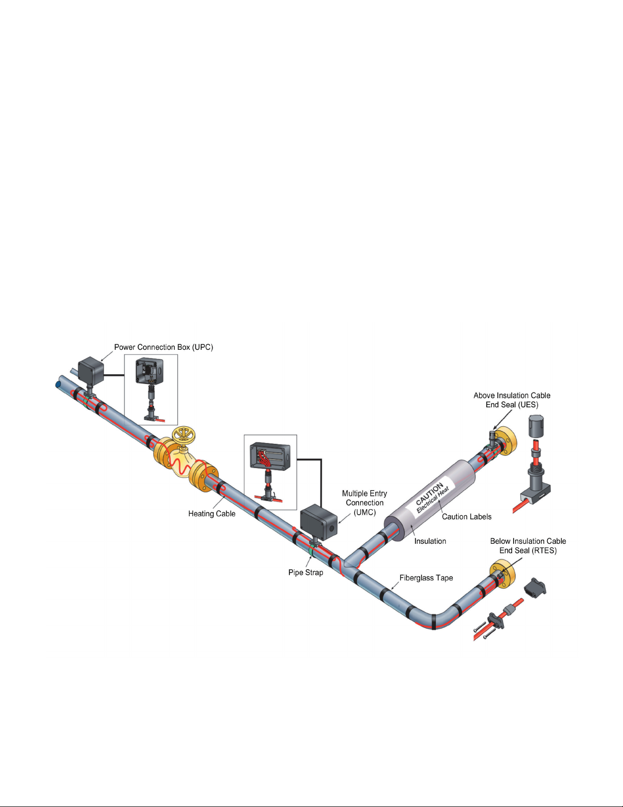
System Components
A complete electric heat trace system includes the follow-
ing system components – See the figure below for a typical
system.
1. Electric Heat Tracing (Self-regulating, Constant Wattage)
2. Termination Accessories
A. Power Connection
B. Splice/Tee
C. End Seal (under insulation, above insulation or signal
light type)
D. Control Thermostat or RTD Sensor
E. Attachments
i. Fiberglass tape
ii. Aluminum tape for plastic pipe install
iii. Pipe clamps for termination accessories
iv. Electric Trace Caution Label
3. Controls
A. Thermostats
B. Digital Thermostats
C. Single/Dual Loop Panels
D. Weather Trace Panels
E. IntelliTrace Panels
4. Thermal Insulation
5. Weather Barrier for Insulation

5
Table 1 – Cable Type Overview
Self-Regulating
Constant
Wattage
Mineral
Insulated
Series
Long Line
Hazardous ratings available Yes Yes Yes Yes
Usable on plastic pipe Yes* No No No
Can be cut to length in eld Ye s Yes** No Yes
Can be single overlapped Yes No No No
* SRL only on plastic pipe.
** Must be cut at module point to avoid cold leads.
Table 2 – Maximum Temperatures
Cable Type
Max. Maintain
(Power On)
Max. Exposure
(Power Off) Voltage Rating
SRL 150˚F 185˚F 120, 208-277
SRP 230˚F 275˚F 120, 208-277
SRM/E 302˚F 420˚F 120, 208-277
CWM 320˚F* 392˚F 120, 208-277, 480
SLL 302˚F 450˚F 120, 208-277, 480, 600
MI 1112˚F 1200˚F 120-600
* See Table 15 for maximum maintenance temperatures at each output.
Chromalox Cable Types
Resistance Wire
Binder
Buss Wires
Module Point
Primary Insulation
Tinned Copper Braid (Optional)
Overcoat Over Braid (Optional)
Constant Wattage
Self-Regulating
Mineral Insulated
Alloy 825 Sheath
Densely
Compacted
Mineral Insulation
Twin (Shown) or Single
Resistance Wires
Tinned Copper
Braid (Optional)
Jacket
Conductive Matrix
Buss Wires
Overcoat Over
Braid (Optional)
SLL Long Line
Metallic Braid
High Temperature
Fluoropolymer Jacket
High Temperature
Fluoropolymer Core Matrix
16, 14, 12,10 AWG
Copper Buss Wires
High Temperature
Fluoropolymer
Overjacket
Approvals
Chromalox heating cables and components approved for use
in hazardous and nonhazardous locations. Refer to the spe-
cific product data sheets for details.

6
General Information
Use of Manual
These instructions are to be followed when installing Chro-
malox heating cables on pipes in ordinary locations. Consult
factory for installation of braided cable in hazardous loca-
tions. This manual discusses the installation of two types of
heating cables: parallel cables (SRL, SRP, SRM/E) and series
cables (CWM, MI, SLL). Although they are all resistance type
cables, they have different operating characteristics. These
characteristics may make one type of cable more suitable
for a particular application than another. This manual, how-
ever, is not intended as a product selection manual. Refer
to appropriate application design guide for product selection
guidelines. A chart high-lighting certain characteristics for
Chromalox heating cables can be found on page 5.
For customer support, design assistance, or information re-
garding any other Chromalox products, please contact your
local Chromalox representative or use the information below.
Chromalox, Inc.
103 Gamma Drive
Pittsburgh, PA 15238
Tel: +1 (412) 967-3800
Fax: +1 (412) 967-5148
Email: [email protected]
www.chromalox.com
Storage
The heating cables should be stored in their shipping cartons
or on reels in a dry atmosphere until they are ready to be in-
stalled. They should be stored in a clean location, where they
are protected from mechanical damage.
Storage temperature range: 0°F(-18°C) to 140°F(60°C).
Important Installation Notes
The following notes should be reviewed prior to installation.
• Always install tracing at the 4 or 8 o’clock position on a
pipe.
• Do not attempt to heat trace any piece of equipment
which will not be insulated.
• Allow a minimum of 2” between cable runs.
• Always install heat tracing on the outside radius of el-
bows.
• Never install heat tracing over expansion joints without
leaving slack in the cable.
• Pumps and small vessels should be heat traced and con-
trolled with the piping on the inflow end. The cable on the
pump or vessel should be physically separate to permit
disconnection during maintenance or removal.
• Use aluminum foil tape to cover the heating cable when-
ever the cable is not in good contact with the pipe (i.e. at
supports, valves, pumps, etc.).
• Separately controlled circuits should be provided on dead
end legs and closed bypasses.
• No heat tracing circuit should extend more than two feet
beyond a point where two or more pipes join when such
junctions permit optional flow paths. In such cases, sepa-
rately controlled traces should be used.
• The minimum installation temperature for all Chromalox
heating cables is -76˚F (-60˚C).
• Chromalox Type SRL heating cables are well suited for
heat tracing plastic pipes. Consult “Chromalox Design
Guide for Heat Tracing Products” for design recommen-
dations. Installation details apply for plastic pipe only
when Type SRL heating cable is used. Consult factory for
applications involving other products.
• Always ensure that the heating cable load is compatible
with the rating of the selected control systems.
• Only install control devices where the electrical conduit
has a low-point drain that prevents condensation from
entering the thermostat enclosure.
NOTICE
These products may be become damaged by moisture. Damage to electrical components,
electrical properties, corrosion or other damage may occur if equipment is not stored
in a dry location. Visual inspection and electrical checks must be performed prior to
installation to ensure safety and proper operation. See equipment installation manual
or contact the factory for more information. 800-443-2640 or www.chromalox.com.
STORE IN DRY AREA

7
Installation
Pre-Installation Guidelines
Before attempting to install the heating cable, read this in-
struction sheet and those enclosed with the accessories to
familiarize yourself with the products. Complete the following
pre-installation steps:
• Verify that the selection of heating cable type and rating
is in accordance with the procedures located in the ap-
plicable application design guide.
• Ensure that the voltage rating of the heating cable is ac-
ceptable for the available service voltage.
• Walk along the pipe segment that is to be traced and plan
out the path for the heating cable on the pipe.
• Remove any obstacles or sharp edges that are present
along the pipe segment.
• Open package and visually check for breaks or nicks in
the cable jacket. File claim with carrier if any damage is
found.
• After removing the cable from the carton or wrapping,
measure the insulation resistance of the unit from buss
wires to braid at 2,500 VDC to assure the cables have not
been damaged during shipping and handling. If the cable
has no braid, uncoil the cable onto a metal surface and
check resistance between the buss wires and the metal
surface. See Table 4 for acceptable minimum insulation
resistance readings and page 32 for a detailed explana-
tion on how to conduct the insulation resistance test.
ELECTRIC SHOCK HAZARD. Any cable with an in-
sulation resistance reading less than 20 megohms
before installation should not be installed. Contact
your local Chromalox representative.
• Ensure all pipes, tanks etc. have been hydrostatically
tested prior to the installation of the heating cable.
• Ensure all cable ends, connections, and surfaces are dry
prior to installation.
ELECTRIC SHOCK HAZARD. Disconnect all power
before installing or servicing heating cable. Failure
to do so could result in personal injury or property
damage. Heaters must be installed by a qualified
person in accordance with IEC 62086-2:2001.
Any installation involving electric heating must be
effectively grounded in accordance with IEC 62086-
2:2001 to eliminate shock hazard.

8
Installation Guide: Single Run of Cable
If installing a single run of heating cable on a pipe, follow the
steps below:
1. Mount the reel of cable on a holder and place near one
end of the pipe run to be traced. Choose the end from
which it will be the easiest to pay out the cable.
2. Pay out the cable from the reel and loosely string along
the piping, making sure the cable is always next to the
pipe when crossing obstacles. For example, if the heater
is on the wrong side of a crossing pipe, you will have to
restring the cable or cut and splice it.
To prevent damage to cable, avoid such things as:
— Pulling the cable over sharp edges.
— Forcibly pulling the cable free if it snags while
being paid out.
— Walking on or subjecting the cable to other abuse
which could cause mechanical damage.
3. When you reach the end of the circuit, secure the heating
cable to the pipe using glass tape or plastic cable tie with
a temperature rating compatible with the heater cable.
If this end is to have an end seal installed, remember to
leave about a foot of extra cable. If it is a power connec-
tion, leave about two feet of extra heater cable.
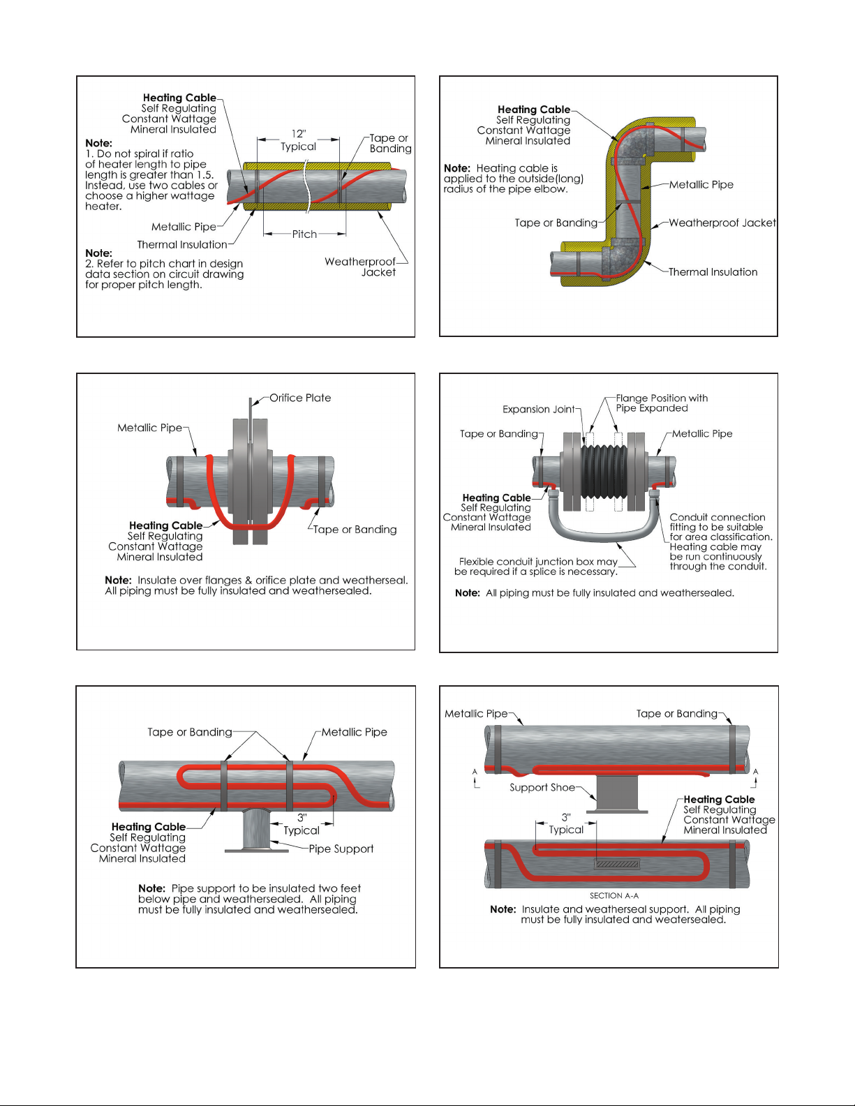
4. If the heater cable is to be spiraled, go to step 4a.
Begin attaching the cable to the pipe about every foot (0.3
meters).
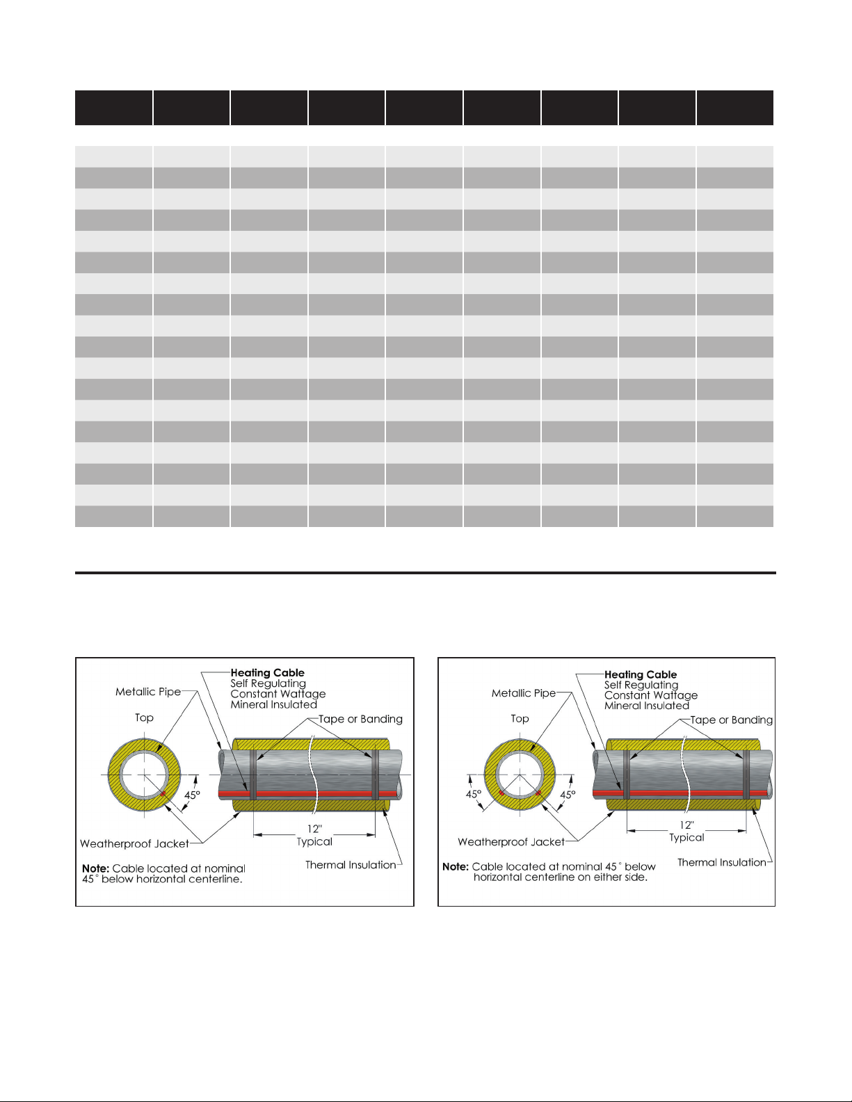
Place the cable on the bottom half of the pipe at the 4 or
8 o’clock position. Refer to installation detail AD1. Go to
step 5.
a. Note the path of the heater cable and the spiral factor
of the design. A simple way to think about spiral factor
is: A 1.1 spiral factor means install 11 feet of heating
cable on every 10 feet of pipe, etc. At about every 10
feet of pipe, pull the required amount of cable and let
hang in a loop, and attach the cable to the pipe.
b. Rotate the loops around the pipe until all the slack has
been taken up. Even out the spirals of the heater cable
and secure to the pipe as necessary to obtain good
contact. The entire circuit can be installed with hang-
ing loops with the spiraling on the pipe being done
when you trace the heat sinks. Refer to installation de-
tail AD3.
5. At a heat sink (pipe supports, valves, pumps, reducers,
gauges, bucket strainers, etc.), attach the heater cable
to the pipe just before the heat sink. Refer to the design
specs or Table 3 to determine the amount of heater cable
you need to install on the heat sink. Pull this amount of
cable into a loop, attach the heater cable on the other
side of the heat sink and continue attaching the cable
down the pipe as before.
6. When you reach the heater cable reel, you should have
the heater cable attached all along the pipe, with the cor-
rect amount of heater cable pulled in loops at all heat
sinks. Attach the cable to the pipe, (leave an extra foot if
at an end seal, two feet if at a power connection) and cut
the heater cable from the reel.
7. Install the heater cable loops on the heat sinks. Refer to
the proper installation detail AD5-AD12 for a general idea
of how to install the cable, but remember:
• It is important to get the proper amount of heater ca-
ble on the heat sink, rather than exactly as the detail
shows. The detail is just a guide.
• Self-regulating heater cables are very flexible and can
be single overlapped for installation ease. Feel free to
use this feature when you can.
• By having the cable installed this way, it can be re-
moved easily from the heat sink without cutting of ac-
cess to, or removal of the heat sink is required.
Note: If a tee is designed into the system, or if you are using
two or more short cable lengths to complete a circuit, allow
two or three feet of each cable to overlap. This will allow flex-
ibility in assembling the connection kit and locating it on the
pipe.
FIRE HAZARD. Do not overlap constant wattage
heating cables.

9
Installation Guide: Multiple Cable Runs
There are two cases where you will need to install more than
one heater cable on a pipe:
• When the design calls for more than one cable.
• When the lines being heat traced are considered impor-
tant enough to install a backup (redundant) heat tracing
system.
The installation requirements are different for these cases.
Installing Multiple Heater Cables for
Design Requirement
The most common multiple cable requirement is two cables
on a pipe. Below are the recommended techniques for the
two cable systems. They also apply to installations where
three or more cables are to be installed on a pipe.
There are two ways of paying out two heater cables along
a pipe. The first is to locate two reels of heater cable and
supply one cable from each. This method works for all types
of piping runs. However, it may increase material waste by
leaving unusable lengths from two reels. The second way is
to supply both cables from one reel. This method is gener-
ally the easiest for relatively straight, simple piping runs. For
each circuit, decide which method to use and then go to the
appropriate part below.
1. Supplying cable from two reels
The general procedure here is the same as given earlier,
but there are a few things to do to make sure the system
is correctly done.
a. At each heat sink, the easiest thing to do is supply the
extra heater called for by the design drawing from only
one heater cable. This avoids having to measure out
half of the requirement from each cable.
b. When doing the previous step, leave a small loop in
the other cable at equipment which may be serviced,
such as pumps, valves, instruments, etc. This is so
both heater cables may be removed enough for future
access.
2. Supplying cable from one reel
The general procedure is the same as given earlier, but
there are a few things to do to make sure the system is
correctly done.
a. With this method, a loop is pulled for the entire circuit.
To do this, attach the end of the heater cable to the
pipe near the heater cable reel. Remember to leave
enough extra cable for the type of connection to be
installed.
b. Begin pulling the cable off the reel in a large loop down
the piping run. Be sure to keep the cable next to the
pipe. Moving down the run, continue attaching the ca-
ble to the pipe, leaving the side of the loop going back
to the reel unattached.
c. You will want both sides of the loop to be about the
same length to avoid future problems. Also, it is easier
to install the extra cable required at each heat sink
from only one cable. Therefore, pull the right amount
of extra heater cable needed at every second heat
sink from the side of the loop you are attaching to the
pipe. At the remaining serviceable heat sinks (pumps,
valves, instruments, etc.) do not forget to leave a short
loop of cable for slack when access to the equipment
is needed.
d. When the end of the piping run is reached, pull the
proper amount of extra cable for the connection to be
installed.
e. Now, begin working the remaining side of the loop
back toward the reel, installing it on the pipe and heat
sinks as required.
Installing Backup (Redundant)
Systems
The purpose of a backup system is to provide the proper
amount of heat from the second heater cable if there are
problems with the first. Therefore, each cable must be in-
stalled so it can do the job alone. The simplest way to do this
is to install the first heater cable as described in the Installa-
tion Guide: Single Run of Cable section. Then, go back and
install the backup heater cable the same way.
There are several things to keep in mind:
• The power connections and end seals for the two cables
are often designed to be at opposite ends of the run in a
redundant system. Remember to leave the proper amount
of extra cable for the connection to be installed on each
cable at that end.
• On piping one inch IPS or smaller, it can be difficult to
apply both heater cables with good contact at all places.
The main thing is to get the correct amount of cable in-
stalled. However, try to get as much contact with the pip-
ing and heat sinks from both cables as possible.

10
Supplementary Instructions:
ATEX and IECEx Applications
SRL and SRM/E Self-Regulating Heating Cables, U Series
Connection Accessories Type DTS-HAZ, UPC, UMC, UES
and RTES
• Do not bend the cable for a length of 300mm from the
cable gland inlet.
• Connection and termination of Chromalolx ATEX and
IECEx certified cable must be carried out by using the U
Series of certified cable connection kits as supplied by
Chromalox, Inc. These are only to be used for the opera-
tions for which they were designed.
• The supply circuit to the heating cables must be pro-
tected by a safety differential device or equivalent ground
fault protection.
• The earthing braid of the heat trace cable must be bond-
ed to a suitable earth terminal.
• The minimum cable installation temperature for SRL and
SRM/E cable is -40˚C (-40˚F).
• The certified minimum cable exposure temperature for
SRL and SRM/E cable is -60˚C (-76˚F).

11
Other Installation Considerations
Pipe Hanger
When using a pipe hanger, ensure that the heating cable is
not pinched between the pipe and the hanger. Damage to
the cable can result in electrical arcing, arc faults, and arc
flashes.
Slab Penetrations
Before installing heating cables on a pipe that penetrates a
concrete floor or wall, be sure that the hole comfortably fits
both the pipe, cable, and insulation. Do not damage or cut
the heating cable during installation. Make sure that the cable
is not pinched between the pipe and the concrete floor and
wall when the hole is sealed. When fire stopping around floor
and wall penetrations, aviod damaging or cutting the heating
cable. The heating cable should be protected by a tube or
conduit and should not be installed directly into the sealing
material.
Bending the Heating Cable
Do not attempt to bend the heating cable in the flat plane,
as it may be damaged. The minimum bending radius for all
Chromalox heating cables is six times the minor diameter.
Heat Sinks
Refer to the design specs or Table 3 to determine the amount
of heater cable you need to install on each heat sink. Install
the heater cable on the heat sinks as explained in installation
details AD5-AD12. However, remember that the detail is just
a guide. It is important to get the proper amount of heater ca-
ble on the heat sink, rather than exactly as the detail shows.
12
Typical Installation Detail
Table 3 – Additional Cable Lengths Required for In-Line Components (Based on Iron Pipe Size)
Piping Size Gate Valve
Globe
Valve Ball Valve
Butterfly
Valve
Shoe
Support
Hanger
Support
Sleeper
Support
Flange
Pair
Dimensions in Feet (Ft.)
1/2 in. 1.00 1.00 1.00 1.00 1.00 1.00 1.00 0.30
3/4 in. 1.50 1.00 1.00 1.00 1.50 1.00 1.00 0.30
1 in. 2.00 1.00 1.00 1.00 1.50 1.00 1.00 0.30
1-1/2 in. 2.50 1.50 1.50 1.50 2.00 2.00 2.00 0.30
2 in. 2.50 2.00 2.00 2.00 2.00 2.00 2.00 0.30
2-1/2 in. 2.50 2.00 2.00 2.00 2.00 2.00 2.00 0.30
3 in. 3.00 2.50 2.50 2.50 2.00 2.00 2.00 0.50
4 in. 4.00 3.00 3.00 3.00 2.50 2.50 2.50 0.50
6 in. 5.00 3.50 3.50 3.50 2.50 2.50 2.50 0.80
8 in. 7.00 4.00 4.00 4.00 2.50 2.50 2.50 0.80
10 in. 8.00 4.50 4.50 4.50 3.00 3.00 3.00 0.80
12 in. 9.00 5.00 5.00 5.00 3.00 3.00 3.00 0.80
14 in. 10.00 5.50 5.50 5.50 3.00 3.00 3.00 1.00
16 in. 11.00 6.00 6.00 6.00 3.50 3.50 3.50 1.00
18 in. 12.00 7.00 7.00 7.00 3.50 3.50 3.50 1.00
20 in. 13.00 7.50 7.50 7.50 3.50 3.50 3.50 1.00
22 in. 13.00 7.50 7.50 7.50 3.50 3.50 3.50 1.00
24 in. 15.00 8.00 8.00 8.00 4.00 4.00 4.00 1.00
AD1 - One Run of Cable AD2 - Two Runs of Cable
13
AD4 - One Run of Cable at Pipe Elbow
AD6 - Expansion Joint
AD3 - One Cable-Spiralling Method
AD5 - Orifice Flange
AD7 - Welded Support AD8 - Shoe Support

14
AD10 - Pressure Gauge
AD12 - Level Gauge
AD9 - Valve
AD11 - Diaphragm Pressure Gauge
AD14 - U Series Splice & Tee Connection
AD13 - U Series Power Connection

15
SOLIDWORKS Educational Product. For Instructional Use Only.
AD16- DL Series Below Insulation End Seal
AD15 - EL Series Splice and Tee Kit
AD17 - DL Series Power ConnectionAD16-2 U Series Above Insulation End Seal
SOLIDWORKS Educational Product. For Instructional Use Only.
AD19 - Sensor PlacementAD18 - DL Series Splice & Tee Connection
16
Wiring
ELECTRIC SHOCK HAZARD. Disconnect all power
before installing or servicing heating cable. Failure
to do so could result in personal injury or property
damage. Heater must be installed by a qualified per-
son in accordance with the National Electrical Code,
NFPA 70.
ELECTRIC SHOCK HAZARD. Any installation involv-
ing electric heating cables must be performed by a
qualified person and must be effectively grounded
in accordance with the National Electrical Code to
eliminate shock hazard.
ACCESSORIES:
• Selection of installation accessories should be in accor-
dance with ChromaTrace 4 design software program. En-
sure accessories are rated for the area where they are lo-
cated. If Chromalox accessories are not used with cable,
all third-party approvals are voided.
• Only use Chromalox installation kits and use them only for
the operations for which they are designed.
• The instructions included in the Chromalox installation
accessories must be followed for the third-party approv-
als (UL, FM, CSA, ATEX, IECEx, etc.) to apply.
• Junction boxes must be in accordance with the require-
ments of the area classification.
• All outdoor junction boxes must be located above grade
level. Covers should be kept on the boxes at all time when
not being worked in.
• All terminations must be protected from the weather and
from physical damage by locating them either under the
weather-proof insulation or inside an appropriate junction
box.
• All equipment must be properly grounded.
• Install installation accessories according to the instruc-
tions included in the kits and per installation details AD13
through AD19.
To prevent equipment damage, Circuits fed from
overhead lines should be protected by secondary
lighting arrestors.
CONTROLS:
• All heating circuits should have temperature controls.
Temperature control of the pipeline can be obtained
through various Chromalox temperature controls.
• Contactors must be used when load currents exceed the
rating of the thermostat contacts. Equipment protection
ground fault (30 mA EPD) thermal breakers are recom-
mended with types SRL, SRP, SRM/E, SLL, and CWM.
• The temperature control should be mounted in a location
where it will not be subjected to excessive shock or vibra-
tion.
• Line sensing temperature sensors should be mounted in
accordance with installation detail AD19.
• Ambient sensing temperature sensors should be located
at a point where the lowest ambient temperature is ex-
pected.
To prevent equipment damage, handle and secure
temperature sensors, especially thermostat bulbs
and capillaries with care to avoid distortion or
crimping which might impair control accuracy.
• Exposed thermostat capillaries should have mechanical
protection.
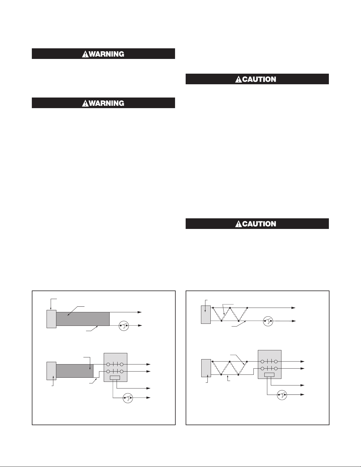
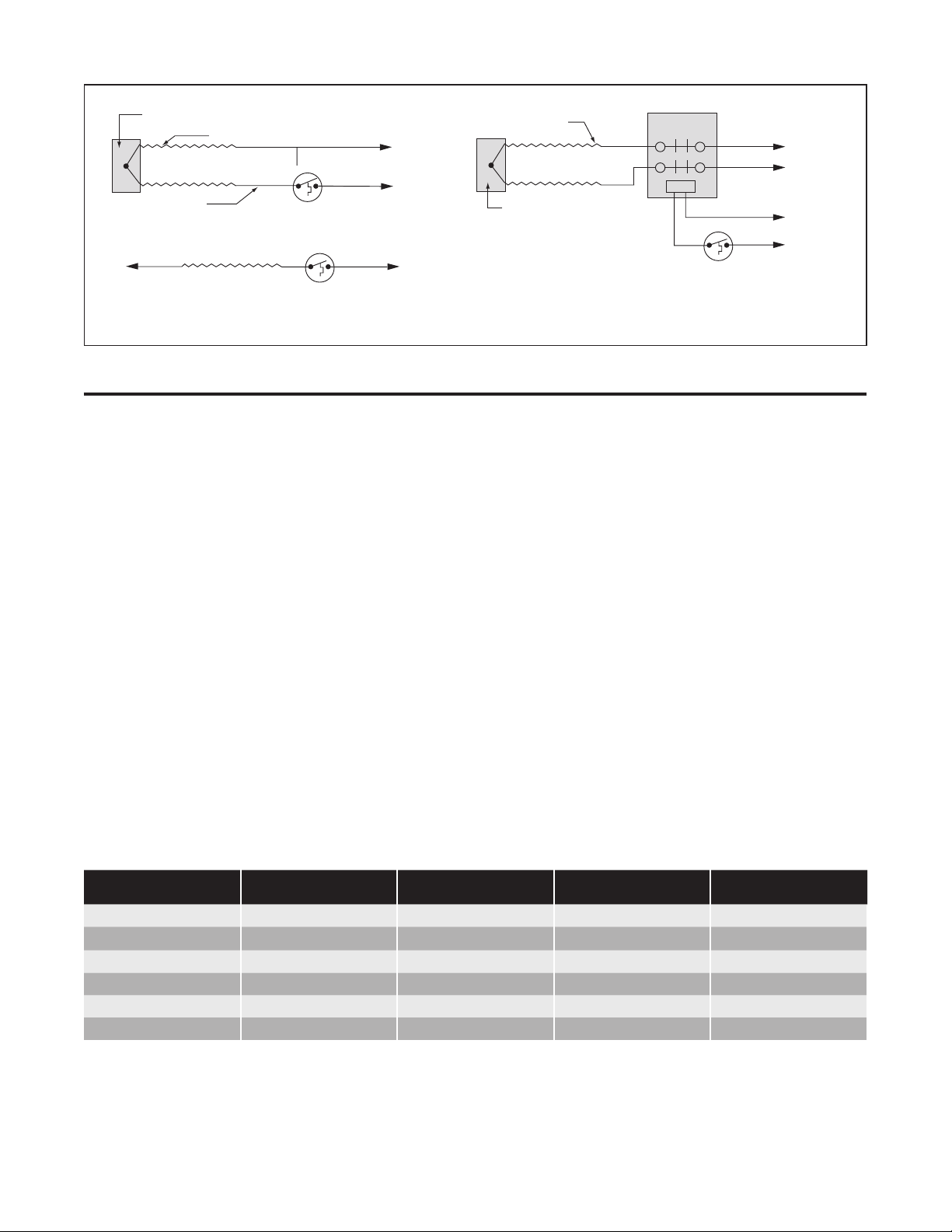
End Cap
Buss Wire
Heat Generating Matrix
Thermostat
L1
L2
Power Supply
End Cap Buss Wire
Heat Generating Matrix
Thermostat
Contactor
L1
L2 Power
Supply
Control
Circuit
I. Self-Regulating
End Cap
Buss Wire
Heat Resistance Wire
Thermostat
L1
L2
Power Supply
End Cap Buss Wire
Heat Resistance Wire
Thermostat
Contactor
L1
L2 Power
Supply
Control
Circuit
II. Constant Wattage
17
Installation Testing
To identify potential damage, installation testing should be
completed at the following times:
• Prior to installing the heating cable
• Prior to installing the connection kits
• Prior to insulating the pipe
• After insulating the pipe
• Prior to energizing the cable
• During periodic system check-ups
• After maintenance/repair work
As part of the installation testing, complete the following
steps:
1. Visually inspect the heater cable and temperature con-
trols for signs of mechanical damage. If damage is seen,
either replace the complete heater cable, or cut out the
damaged section and replace using the proper splice
connection for the area and cable you are using.
2. Inspect all connections to be sure they are correctly as-
sembled. Be sure each heater cable entry to a connection
has a grommet and the compression plates and caps are
properly tightened.
3. Determine the insulation resistance of the circuit using at
least 1,000 VDC. It is strongly recommended that higher
test voltages be used. Polymeric cables (SR, SLL, and
CWM) should be tested at 2,500 VDC. Always perform
this test at the power connection. See Table 4 for mini-
mum insulation resistance readings. Any cable with an in-
sulation resistance below the recommended value should
be removed and factory should be contacted. See page
31 for a detailed explanation on how to conduct the insu-
lation resistance test.
4. Check voltage at the end of circuit and record in the log
on page 33. See page 31 for information on how to com-
plete the end of circuit voltage test.
Table 4 – Minimum Insulation Resistance Readings
Delivery
Installation
Pre-Insulation
Installation
Post-Insulation Maintenance
Chromalox SRL 20 MΩ20 MΩ5 MΩ 5 MΩ
Chromalox SRP 20 MΩ20 MΩ5 MΩ 5 MΩ
Chromalox SRM/E 20 MΩ20 MΩ5 MΩ 5 MΩ
Chromalox CWM 20 MΩ20 MΩ5 MΩ 5 MΩ
Chromalox MI 20 MΩ 20 MΩ 5 MΩ 5 MΩ
Chromalox SLL 20 MΩ20 MΩ5 MΩ 5 MΩ
End Cap
End Cap
Cold Lead
Heat Resistance Wire
Heat Resistance Wire
Thermostat
Thermostat
Thermostat
L1
L1
L2
L2
Power Supply
Contactor
L1
L2 Power
Supply
Control
Circuit
OR
III. Mineral Insulated / Series Long Line

18
Heating Cable Components
Connection Kits
Table 5 – U Series Connection Kits Overview
Catalog Number Description
Installation
Manual
UPC
Power Connection
Box
NEMA 4X rated junction box designed to connect
cables to customer supplied power wiring. This
kit provides water-resistant cable entry for one
cable, enclosure support, terminal block, and a
water-resistant corrosion-resistant wiring enclo-
sure with a 3/4” opening to accept a conduit hub
(CCH-2 or equal)
PJ495
UMC
Multiple Entry Power
Connection Box
NEMA 4X rated junction box designed to connect
two or three cables. This kit provides water-
resistant cable entry, enclosure support, terminal
block, and a water-resistant, corrosion-resistant
wiring enclosure. In addition to splicing or teeing
cables, this model can be used to provide power
connection to up to three cables from one con-
nection kit.
PJ497
UES
Above Insulation End
Seal Kit
NEMA 4X rated end seal designed to terminate
cables. This kit provides water-resistant cable
entry for one cable. It has a corrosion-resistant
pipe support that brings the cable end outside of
the insulation for easy access. PJ496
UESL
End Seal Signal
Light Kit
NEMA 4X rated end seal designed to seal one
cable and indicate power on with universal volt-
age 120-277 LED indicator light. This model
provides water-resistant cable entry, enclosure
support, terminal block, and corrosion-resistant
wiring enclosure. Available in red and green. PJ448
USL
Power/End Seal
Signal Light Kit
NEMA 4X rated end seal designed to power or
seal one cable and indicate power on with uni-
versal voltage 120-277 LED indicator light. This
model provides water-resistant cable entry,
enclosure support, terminal block, and corro-
sion-resistant wiring enclosure. PJ937
SSK
Single Entry
Sealing Kit
This kit provides water-resistant cable entry for
one cable. It has a corrosion-resistant pipe sup-
port that brings the cable end outside of the
insulation for easy connection to power.
PJ498

19
Table 6 – U Long Line Series Connection Kits Overview
Catalog Number Description
Installation
Manual
UPC LL
Power Connection
Kit
NEMA 4X rated junction box designed to connect
SLL heating cables to customer supplied power wir-
ing. This kit provides water-resistant cable entry for
one cable, enclosure support, crimp connections,
cold leads, and a water-resistant corrosion-resistant
wiring enclosure with an opening to accept a 3/4"
conduit hub.
PJ951
UMC LL
Multiple Entry Power
Connection Box
NEMA 4X rated junction box designed to connect
two SLL heating cables to each other. This kit pro-
vides water-resistant cable entry for one cable,
enclosure support, crimp connections, and a water
resistant corrosion-resistant wiring enclosure with an
opening to accept a 3/4" conduit hub.
PJ949
UES LL
End Seal
Connection Kit
NEMA 4X rated junction box designed to terminate
SLL heating cables outside of the insulation. This kit
provides water-resistant cable entry for one cable,
enclosure support, crimp connections, and a water-
resistant corrosion resistant wiring enclosure with an
opening to accept a 3/4" conduit hub.
PJ950
Table 7 – DL Series Connection Kits Overview
Catalog Number Description
Installation
Manual
RTES
End Seal Kit
NEMA 4X rated enclosure that provides waterproof
cable entry for one (1) cable. The fitting has two (2)
different mounting surfaces: one for pipes with a
diameter of 3” or more, and one for smaller pipes PJ450
RTPC
Power Connection
Kit
NEMA 4X rated junction box that provides water-
proof cable entry for up to three (3) cables with an
opening to accept a 3/4” conduit hub (Chromalox
CCH-2 or equal).
PJ451
RTST
Slice & Tee Kit
NEMA 4X rated junction box that provides water-
proof cable entry for two (2) cables for a splice or
three (3) cables for a tee.
PJ452

20
Table 8 – HL Series Connection Kit Overview
Catalog Number Description
Installation
Manual
HL-PC
Power Connection
Box for Hazardous
Locations
Division 1 certified junction box and seal
fitting. The kit is designed to connect self-
regulating cables to customer supplied
power wiring. The pipe stand-off and seal
fitting combination provides a water resis-
tant and explosion proof seal. The junction
box has a 3/4" opening with top or side
entry for the power connection.
PJ912
HL-S
Splice Kit for
Hazardous Locations
Division 1 certified junction box and seal
fittings. The kit is designed to splice two
self-regulating cables. The cable entry fit-
ting and seal fitting combination provides a
water-resistant and explosion proof seal.
PJ920
HL-T
Tee Kit for Hazardous
Locations
Division 1 certified junction box and seal
fittings. The kit is designed to splice three
self-regulating cables. The cable entry fit-
ting and seal fitting combination provides a
water-resistant and explosion proof seal.
PJ921
HL-ES
End Seal for
Hazardous Locations
Division 1 certified junction box and seal
fitting. The kit is designed to terminate a
run of self-regulating cable. The pipe
stand-off and seal fitting combination pro-
vides a water resistant and explosion proof
seal.
PJ918
This manual suits for next models
5
Table of contents
Other Chromalox Cables And Connectors manuals


