CABLE GLAND FOR USE WITH SINGLE WIRE ARMOUR (SWA), WIRE BRAID, STRIP,
AND TAPE ARMOUR (T3CDSPB VERSION CAN ALSO BE USED ON CABLE WITH A LEAD
SHEATH). FOR USE IN EXPLOSIVE ATMOSPHERES.
INCORPORATING EU DECLARATION OF CONFORMITY TO DIRECTIVE [2014/34/EU]
CMP TRITON™ CDS™ DELUGE PROOF CABLE GLAND FEATURING
COMPENSATING DISPLACEMENT SEAL SYSTEM.
TECHNICAL DATA EXPLOSIVE ATMOSPHERES CLASSIFICATION
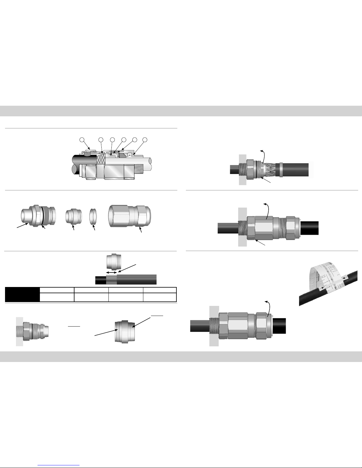
INSTALLATION INSTRUCTIONS
Installation should only be performed by a competent person using the correct tools. Read all instructions before beginning installation.
ACCESSORIES
The following accessories are available from CMP Products, as optional extras, to assist with fixing, sealing and earthing: Locknut, Earth Tag, Serrated Washer, Entry Thread (I.P.) Sealing Washer, Shroud
CMP Products Limited on its sole responsibility declares that the equipment referred to herein conforms to the requirements of the ATEX Directive 2014/34/EU and the following standards:
EN 60079-0:2012+A11:2013, EN 60079-1:2014, EN 60079-7:2015, EN 60079-15:2010, EN 60079-31:2014
David Willcock - Certification Engineer (Authorised Person)
CMP Products Limited, Cramlington, NE23 1WH, UK
24th June 2015
CABLE GLAND TYPES
T3CDS & T3CDSPB
INSTALLATION INSTRUCTIONS FOR
CMP CABLE GLAND TYPES
T3CDS & T3CDSPB
CERTIFICATION CONDITIONS
1. The T3** Type cable glands shall not be used to terminate on braided cables in group I applications.
2. The glands when used for terminating braided cables are only suitable for fixed installations. Cables must be effectively clamped to prevent pulling or twisting.
Number of turns to
tighten
Outer Seal Tightening Guide
GLAND SIZE
20S16 20S 20 25S 25 32 40 50S 50 63S 63 75S 75
CABLE DIAMETER
0.5 13.2 15.9 20.9 22.0 26.2 33.9
1 12.5 15.3 20.0 21.2 25.4 32.9 40.4 46.7 52.8 59.2 65.9 72.1 78.5
1.5 11.9 14.7 19.0 20.4 24.6 31.9 39.0 45.4 51.4 57.7 64.6 70.6 77.2
2 11.2 14.2 18.1 19.6 23.8 30.8 37.6 44.1 50.0 56.2 63.4 69.2 75.9
2.5 10.5 13.6 17.2 18.8 23.0 29.8 36.2 42.9 48.7 54.7 62.1 67.7 74.6
3 9.8 13.0 16.2 18.0 22.2 28.8 34.8 41.6 47.3 53.2 60.9 66.3 73.3
3.5 9.2 12.4 15.3 17.2 21.4 27.8 33.5 40.3 45.9 51.6 59.6 64.8 71.9
4 8.5 11.8 14.4 16.4 20.6 26.8 32.1 39.0 44.5 50.1 58.4 63.4 70.6
4.5 7.8 11.2 13.4 15.6 19.8 25.7 30.7 37.8 43.2 48.6 57.1 61.9 69.3
5 7.1 10.7 12.5 14.8 19.0 24.7 29.3 36.5 41.8 47.1 55.9 60.5 68.0
5.5 6.5 10.1 12.0 14.0 18.2 23.7 27.9 35.2 40.4 45.6 54.6 59.0 66.7
6 5.8 9.5
Glasshouse Street • St. Peters • Newcastle upon Tyne • NE6 1BS
Tel: +44 191 265 7411 • Fax: +44 1670 715 646
Notified Body: Sira Certification Service, Unit 6, Hawarden Industrial Park, Hawarden, CH5 3US, UK
0518
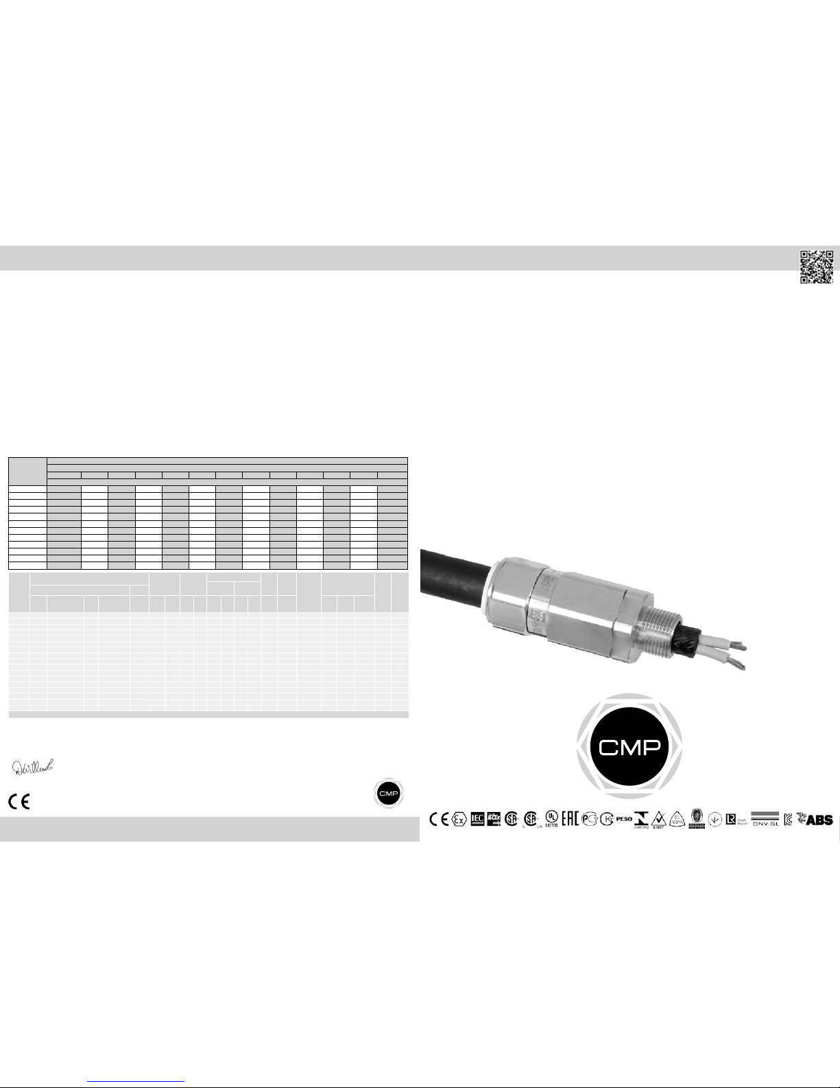
CABLE GLAND TYPE : T3CDS / T3CDSPB
INGRESS PROTECTION : IP66, IP68, NEMA 4X, DELUGE TO DTS01-91
PROCESS CONTROL SYSTEM : BS EN ISO 9001
: ISO / IEC 80079-34:2011
ATEX CERTIFICATION No : SIRA13ATEX1073X, SIRA13ATEX4079X
ATEX CERTIFICATION CODE : ^II 2G, II 1D, Ex d IIC Gb, Ex e IIC Gb, Ex ta IIIC Da, ^ II 3G Ex nR IIC Gc,
^IM2, Ex d I Mb, Ex e I Mb
IECEx CERTIFICATION No : IECEx SIR.13.0028X
IECEx CERTIFICATION CODE : Ex d IIC Gb, Ex e IIC Gb, Ex nR IIC Gc, Ex ta IIIC Da, Ex d I Mb, Ex e I Mb
cCSAus CERTIFICATION No : 1310517X
CSA us CERTIFICATION CODE* : Class II Div 2, Groups E,F and G, Class III,
Class I Zone 1 AEx e II, Class I Zone 2 AEx nR II, Enclosure Type 3,4 and 4X, OIL RES II
c CSA CERTIFICATION CODE : Class I, Div 2, Groups A,B,C and D, Class II Div 2, Groups E,F and G, Class III,
Ex d IIC, Ex e II, Ex nR II, EnclosureType 3,4 and 4X, OIL RES II
UL CERTIFICATION NO : E200163
UL CERTIFICATION CODE : Class I Zone 1,AEx e II
*T3CDS can be used in Class 1, Division 2 Locations for non-explosionproof applications in accordance with Article 501 of the NEC Code
CMP Document No. FI408 Issue 18 CSA Issue 13, IEC Issue 13, UL Issue 12
** Insert “PB” into the code for T3CDSPB glands e.g. 20T3CDSPB1RA
*Stepped cone is for single wire armour and grooved cone is for all other armours
Cable Gland Selection Table
Logos shown for illustration purposes only. Please check certification for details
SCAN FOR INSTALLATION VIDEOS
Note: Standard Seal (Black) Temperature Range = -60°C to +130°C,
High Temperature Seal (Brown) Temperature Range = -20°C to +200°C for High Temperature Seal add ‘HT’ to Ordering Reference after Gland Type e.g. 20ST3CDSHT1RA.
Cable
Gland
Size
Available Entry Threads
(Alternate Metric Thread Lengths Available) Cable
Bedding
Diameter
Overall
Cable
Diameter
Armour Range Across
Flats
Across
Corners Protrusion
Length
Combined Ordering
Reference
(*Brass Metric) Shroud
Cable
Gland
Weight
(Kgs)
Grooved
Cone (X)
Stepped
Cone (W)
Standard Option
Metric Thread Length
(Metric) “E” NPT
Thread
Length (NPT)
“E”
NPT Min Max Min Max Min Max Min Max Max Max Size Type Ordering
Suffix
20S/16 M20 15.0 ½” 19.9 ¾” 3 .1 8.6 6.1 13.1 0.3 1.0 0.8 1.25 24.0 26.4 78.7 20S16 T3CDS 1RA PVC36 0.20
20S M20 15.0 ½” 19.9 ¾” 6 .1 11. 6 9.5 15.9 0.3 1.0 0.8 1.25 24.0 26.4 78.7 20S T3CDS 1RA PVC36 0.20
20 M20 15.0 ½” 19.9 ¾” 6.5 13.9 12.5 20.9 0.4 1.0 0.8 1.25 30.5 33.6 76.2 20 T3CDS 1RA PVC06 0.28
25S M25 15.0 ¾” 20.2 1” 11.1 19.9 14.0 22.0 0.4 1.2 1.25 1.6 37.5 41.3 88.8 25S T3CDS 1RA PVC09 0.44
25 M25 15.0 ¾” 20.2 1” 11.1 19.9 18.2 26.2 0.4 1.2 1.25 1.6 37.5 41.3 88.7 25 T3CDS 1RA PVC09 0.44
32 M32 15.0 1” 25.0 1 ¼”17. 0 26.2 23.7 33.9 0.4 1.2 1.6 2.0 46.0 50.6 90.7 32 T3CDS 1R A P VC11 0.63
40 M40 15.0 1 ¼”25.6 1 ½” 22.0 32.1 27.9 40.4 0.4 1.6 1.6 2.0 55.0 60.5 93.2 40 T3CDS 1RA PVC15 0.91
50S M50 15.0 1 ½” 26 .1 2” 29.5 3 8.1 35.2 46.7 0.4 1.6 2.0 2.5 60.0 66.0 100.7 50S T3CDS 1RA PVC18 1.12
50 M50 15.0 2” 26.9 2 ½” 35.6 44.0 40.4 53.0 0.6 1.6 2.0 2.5 70.1 77.1 105.8 50 T3CDS 1RA PVC21 1.60
63S M63 15.0 2” 26.9 2 ½” 40.1 49.9 45.6 59.4 0.6 1.6 2.0 2.5 75.0 82.5 102.5 63S T3CDS 1RA PVC23 1.73
63 M63 15.0 2 ½” 39.9 3” 47.2 55.9 54.6 65.8 0.6 1.6 2.0 2.5 80.0 88.0 105.4 63 T3CDS 1RA PVC25 1.78
75S M75 15.0 2 ½” 39.9 3” 52.8 61.9 59.0 72.0 0.6 1.6 2.0 2.5 90.0 99.0 110.6 75S T3CDS 1RA PVC28 2.57
75 M75 15.0 3” 41.5 3 ½” 59.1 67.9 66.7 78.4 0.6 1.6 2.5 3.0 100.0 110.0 120.3 75 T3CDS 1RA PVC30 3.33
90 M90 24.0 3 ½” 42.8 4” 66.6 78.6 76.2 90.3 0.8 1.6 3.15 4.0 115.0 126.5 138.9 90 T3CDS 1RA PVC32 4.87
100 M100 24.0 3 ½” 42.8 4" 76.0 90.9 86.1 101.4 0.8 1.6 3.15 4.0 127.0 139.7 128.2 100 T3CDS 1RA LSF33 4.97
115 M115 24.0 4” 44.0 5” 86.0 97.9 101.5 110. 2 0.8 1.6 3.15 4.0 138.0 151.8 161.3 115 T3CDS 1RA LSF34 7.72
130 M130 24.0 5” 46.8 6” 9 7.0 114.9 110.2 123.2 0.8 1.6 3.15 4.0 157.0 172.7 173.3 130 T3CDS 1RA LSF35 9.78
Dimensions are displayed in millimetres unless otherwise stated
1. Cable gland connectors material may be of brass, aluminum or stainless steel.
2. Connectors with metric entry threads are only suitable for Areas Classified in ZONES unless fitted with an approved Metric to NPT thread conversion adaptor.
3. According to US (NEC) wiring method for the types of cables that can be used in Class I Zone 1 and 2 Classified Areas, should be in accordance of NFPA-70
installation wiring method restrictions.
1. Cable gland connectors’ material may be of brass, aluminium or stainless steel.
2. These glands are not suitable for use with flameproof enclosures installed in Group IIC atmospheres, which have a volume greater than 2000 cc (2 Litre).
3. These Glands are for use with Certified Marine Shipboard metal braided cables constructed according to CSA Std. 245 and IEEE45/IEC600092-353 Standards, or
Certified equivalent), for use on Shipboards and Offshore Rigs/platforms only.
4. “Triton CDS” cable gland connectors when installed into Class I, Division 2 Classified Areas, are not suitable to be interfaced with an explosion proof enclosure
containing arcing and sparking devices, unless installed in conjunction with an approved explosion proof sealing fitting.
ATEX & IECEx
CSA us
c CSA