manuals.online logo
Brands
  1. Home
  2. •
  3. Brands
  4. •
  5. Amphenol
  6. •
  7. Cables And Connectors
  8. •
  9. Amphenol THE MODAL SHOP K2060E030 User manual

Amphenol THE MODAL SHOP K2060E030 User manual

K2060E030 Shaker Kit Selection and Quick Start
GuideGuide
DS-0150 revB
www.modalshop.com | 513-351-9919 | rentalteam@modalshop.com
_____ 2050A Lateral Excitation Stand
_____ PCB 288D01 ICP® Impedance Head
_____ PCB 208 Series ICP® Force Sensors. Indicate Model: __________________
_____ Type 2120Gxx threaded (10-32) stainless steel rod stingers. Circle length: 9” 12” 18”
_____ Type 2125Gxx threaded (1/4-28) stainless steel rod stingers. Circle length: 9” 12” 18”
_____ Model 8032S Air Ride Test Support
_____ 2060E-CASE Heavy Duty Shipping Case
2060E Shaker mounted on
trunnion base with
EasyTurn™ handles. Typically
shipped in Pelican case
(2060E-CASE)
Job # _______________________________
Customer ____________________________
This shipment contains ______ K2060E030 Shaker kit(s).
Each kit includes one of each item in this section as noted.
2100E21-400 Amplifier with
cable to shaker (8 ft with 8
Amp inline fuse) and power
cord. Used for 30 lbf output
(standard)
2050E05 Optional amplifier
with cable to shaker (8 ft
with 8 Amp inline fuse) and
power cord. Also provides 30
lbf output, but offers
selectable voltage or current
mode
120 V ☐220 V ☐
_____ Power Plug type
120 V ☐220 V ☐
_____ Power Plug type
2000X03 Shaker accessory kit. Includes:
1
Stinger Kit 2155G12 - 3/32"
2
Stinger Kit 2150G12 - 1/16"
3
Trunnion Bolts - Low Profile
4
10-32 Adaptor
5
Chuck Adaptor [1]
6
Stinger Thumb Nuts (qty 6)
7
Chuck and Collet Kit - 1/32", 1/16", 3/32", 1/8" collets
8
Spare Fuse (shaker) [2]
9
K2160G - Piano Wire Stinger Kit
10
Wrench - 7/16"
11
Wrench - 3/8"
12
Wrench - 3/8"
13
Hex Wrench –1/4"
[1] Typically pre-installed on shaker
[2] Spare fuses (amplifier) - when supplied as a system
Optional Amplifier
Available Accessories/Options
K2060E030 Shaker Kit Selection and Quick Start
GuideGuide
DS-0150 revB
www.modalshop.com | 513-351-9919 | rentalteam@modalshop.com
Connecting the K2060E030 shaker kit
1. Connect shaker cable to amplifier (see below table)
Shaker Cable Wire Color
Function
2050E05
2100E21-400
Red
Armature
OUT / OUT
OUT / SHAKER +
Orange & Blue
Armature
RET / RET
RET / SHAKER -
White/Black
Interlock
+ / +
+ / Interlock +
White
Interlock
INT / INT
INT / Interlock -
Black
Ground
GND / GND
GND / Earth Ground
2. Connect the shaker cable to shaker.
3. Power amplifier with included power cable
4. Connect input signal via the BNC connector labeled “Signal Input”on the back of the 2100E21-400 or to
the BNC connector labeled “AC” on the back of the 2050E05 amplifier.
5. Turn on master power switch and position gain knob to desired setting. Note: Master power switch is
located on the back of the 2100E21-400 amplifier and on the front of the 2050E05 amplifier.
2100E21-400 User Tips
•As a safety measure, if the gain knob is not in the “mute” position when power is turned on, it will need to
be turned to “mute” before amplifier can be used.
•Output clipping error: Anytime the output waveform is clipped due to too much gain or the input
amplitude being too high, the LCD screen will flash the “output clipping” message until the clipping stops.
This helps avoid unwanted output distortion. During clipping, all menus and buttons remain functional.
•Output interlock: Anytime an error or a fault condition occurs while the amplifier is on, the amplifier will
automatically mute and a message will be displayed on the LCD. Consult the “Troubleshooting Guide” in
the manual to fix any problem that caused the error, and press F1 to clear the error message. If the gain
knob is not turned to “mute,” it will have to be turned to “mute” first before the amplifier can be turned
back on.
2050E05 User Tips
•Trip indicator flashing: The “TRIP” indicator flashes if the amplifier has been turned on with the gain out
of the reset position or if the external (fault open) interlock is open. The amplifier output is inhibited
during this interlock condition. The indicator also flashes during a heat sink over-temperature condition.
The amplifier output will be compressed if the overheat condition persists but will automatically restore
itself after the heat sink temperature drops.
•The output peak voltage bar graph indicates the peak voltage applied to the shaker and will indicate
voltage clipping limits and output signal level. It can also be useful in detecting output open circuit
problems. The output RMS current level graph indicates the amount of current being delivered to the
shaker and can be used to prevent overdriving and subsequent damage to connected loads.
Videos and FAQ guides are available online. Feel free to contact The Modal Shop for support at
[email protected] or +1 513-351-9919.

Other Amphenol Cables And Connectors manuals

Amphenol PowerLok 4.0 User manual

Amphenol

Amphenol PowerLok 4.0 User manual

Amphenol RJF 544 Series User manual

Amphenol

Amphenol RJF 544 Series User manual

Amphenol PL183 30 Series User manual

Amphenol

Amphenol PL183 30 Series User manual

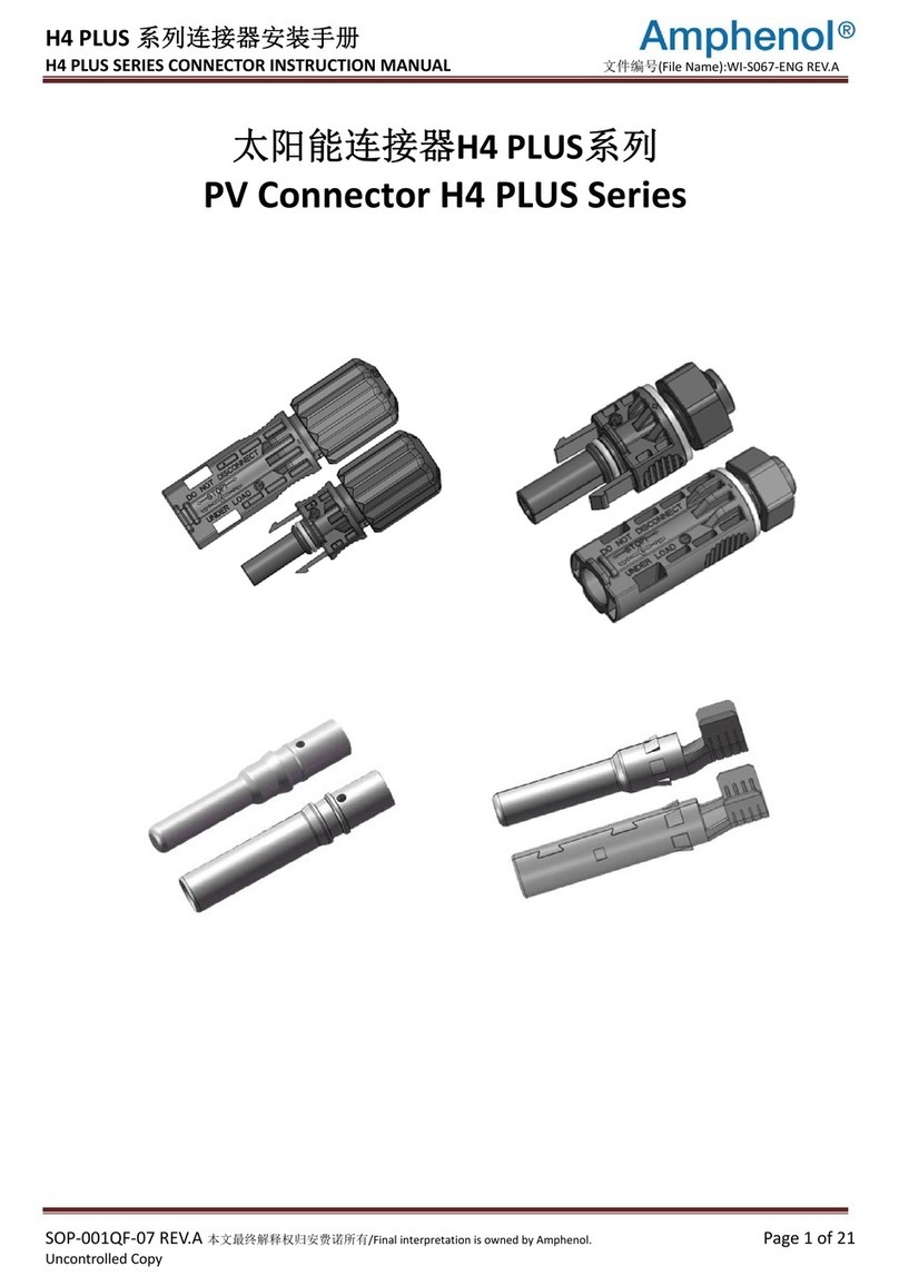
Amphenol H4 PLUS Series User manual

Amphenol

Amphenol H4 PLUS Series User manual

Amphenol H4 Series User manual

Amphenol

Amphenol H4 Series User manual

Amphenol HELIOS H4 User manual

Amphenol

Amphenol HELIOS H4 User manual

Amphenol H4YX User manual

Amphenol

Amphenol H4YX User manual

Amphenol HVSL60061 Series User guide

Amphenol

Amphenol HVSL60061 Series User guide

Amphenol PL18X-301-70-G95 User manual

Amphenol

Amphenol PL18X-301-70-G95 User manual

Amphenol EGT Series User manual

Amphenol

Amphenol EGT Series User manual

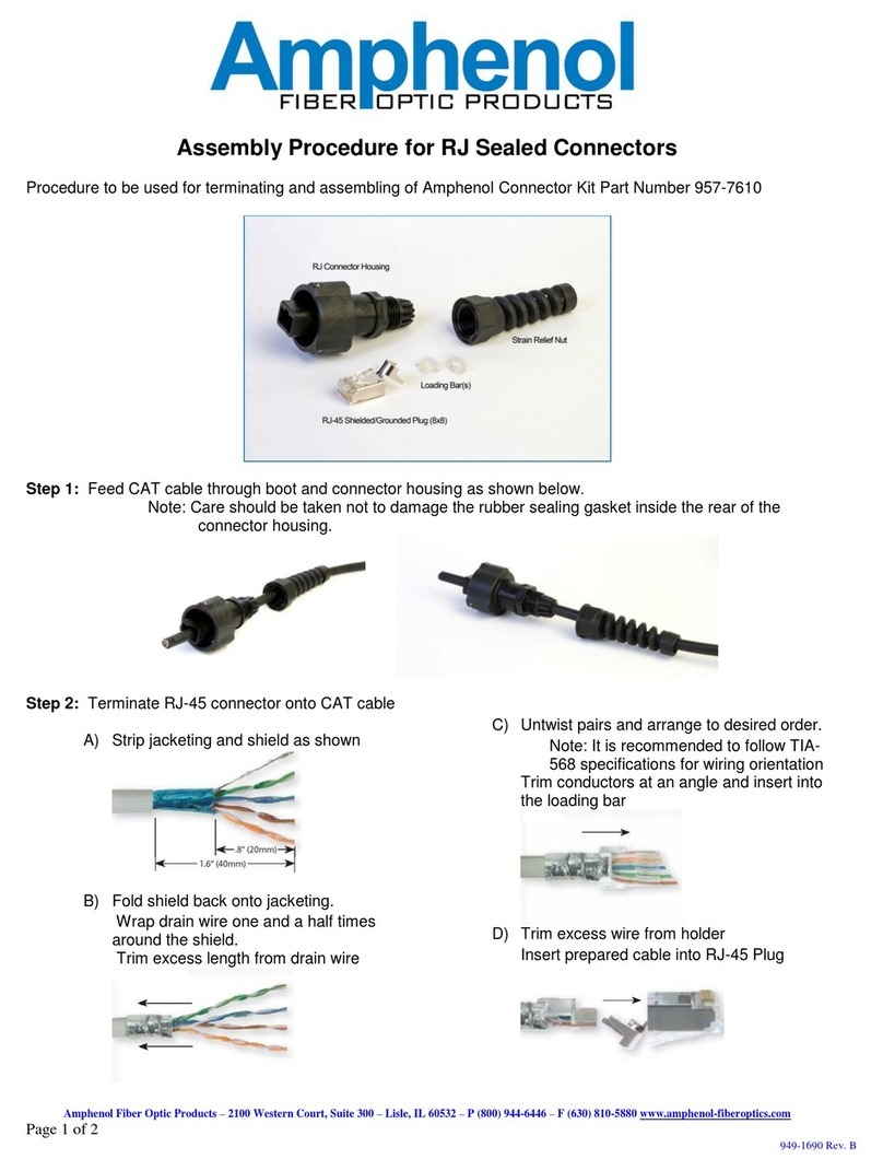
Amphenol 957-7610 Manual

Amphenol

Amphenol 957-7610 Manual

Amphenol SurLok Plus User manual

Amphenol

Amphenol SurLok Plus User manual

Amphenol RJF TV Series User manual

Amphenol

Amphenol RJF TV Series User manual

Amphenol RJField Series User manual

Amphenol

Amphenol RJField Series User manual

Amphenol PL182X-301-70-G95 User manual

Amphenol

Amphenol PL182X-301-70-G95 User manual

Amphenol ePower-lite C10-765779-3XS1 User manual

Amphenol

Amphenol ePower-lite C10-765779-3XS1 User manual

Amphenol Wind-Lok Series User manual

Amphenol

Amphenol Wind-Lok Series User manual

Amphenol PL18 50 Series User manual

Amphenol

Amphenol PL18 50 Series User manual

Amphenol H4 Cable Series User manual

Amphenol

Amphenol H4 Cable Series User manual

Amphenol PL182-301-70-G95 Series User manual

Amphenol

Amphenol PL182-301-70-G95 Series User manual

Amphenol UTX SERIES User manual

Amphenol

Amphenol UTX SERIES User manual

Amphenol RLA00571-25BK User manual

Amphenol

Amphenol RLA00571-25BK User manual

Amphenol RJFTV6MN User manual

Amphenol

Amphenol RJFTV6MN User manual

Amphenol PL18X-201-50-G46 User manual

Amphenol

Amphenol PL18X-201-50-G46 User manual

Popular Cables And Connectors manuals by other brands

Philips SWV6373 Specifications

Philips

Philips SWV6373 Specifications

GEM BLN-RJ45 manual

GEM

GEM BLN-RJ45 manual

Philips SWA3303W Specifications

Philips

Philips SWA3303W Specifications

Philips SWA6375 Specifications

Philips

Philips SWA6375 Specifications

VPC 9050 user manual

VPC

VPC 9050 user manual

Marshall Excelsior MEP840H-24/16 Series manual

Marshall Excelsior

Marshall Excelsior MEP840H-24/16 Series manual

Winegard TRAV'LER RP-SK41 instruction manual

Winegard

Winegard TRAV'LER RP-SK41 instruction manual

knapp RICON 40 Construction manual

knapp

knapp RICON 40 Construction manual

EKVIP 022413 operating instructions

EKVIP

EKVIP 022413 operating instructions

Revox Re:connect RS232 Splitter manual

Revox

Revox Re:connect RS232 Splitter manual

Tripp Lite P222-050 Specification sheet

Tripp Lite

Tripp Lite P222-050 Specification sheet

IPEX MINIFLEX 2-BF instruction manual

IPEX

IPEX MINIFLEX 2-BF instruction manual

Jinko Solar PV-JK03M Series installation manual

Jinko Solar

Jinko Solar PV-JK03M Series installation manual

Tripp Lite N001-005-BK Specification sheet

Tripp Lite

Tripp Lite N001-005-BK Specification sheet

Tripp Lite N422-01M Specification sheet

Tripp Lite

Tripp Lite N422-01M Specification sheet

Tripp Lite B118-002 owner's manual

Tripp Lite

Tripp Lite B118-002 owner's manual

Rocket Fish ND-GWII1122 Quick setup guide

Rocket Fish

Rocket Fish ND-GWII1122 Quick setup guide

AVLink 128828UK user manual

AVLink

AVLink 128828UK user manual

manuals.online logo
manuals.online logoBrands
  • About & Mission
  • Contact us
  • Privacy Policy
  • Terms and Conditions

Copyright 2025 Manuals.Online. All Rights Reserved.