manuals.online logo
Brands
  1. Home
  2. •
  3. Brands
  4. •
  5. Chromalox
  6. •
  7. Heater
  8. •
  9. Chromalox CKH Installation and operating instructions

Chromalox CKH Installation and operating instructions

CKH-TD13 1-Pole Thermostat Kit 22A @ 120/240V 0.4 S 352321
CKH-TD23 2-Pole Thermostat Kit 22A @ 120/240V 0.4 S 352330
Model Description Weight Stock PCN
(Lbs.)
WARNING: Hazard of Electric Shock. Disconnect all
power before installing heater.
WARNING: Hazard of Electric Shock. Any installation
involving electric heaters must be effectively ground-
ed in accordance with the National Electrical Code to
eliminate shock hazard.
WARNING: Do NOT store or use gasoline or other flam-
mable vapors and liquids in the vicinity of the heaters.
Failure to comply can result in explosion or fire.
To prepare the heater for installation, first check that heater name-
plate voltage is the same as the electrical service.
Kickspace Installation —
Note: Unit should be installed so that it is not directly under sink or
other frequently used work area as air temperature may be uncom-
fortably warm. Also, if carpeting is on floor, mount unit so bottom of
grille is level or above the top of carpet pile.
1. Measure area of intended use. If there is not sufficient room for the
trim frame, the frame may be removed by removing Screw “A”
(see Figure 1). Re-insert grille.
2. Cut 22-3/8” x 3-5/8” opening (see Figure 2). Keep clearance area
free of obstructions.
3. Bring in proper service cable to left or rear of 10” minimum area
as shown in Figure 2.
4. Electric wiring to heater must be installed in accordance with the
National Electrical Code and with local codes by a qualified person.
WARNING: Use copper conductors only..
5. Remove heater cover and appropriate knockout. Attach service
cable to unit with approved connector and connect color to color in
outlet box. To change wattage or voltage connections, see Figure 4.
6. Replace cover, slide unit into opening, and secure each side. (See
Figure 1.) Note: Make sure unit is installed right side up. Refer to
“TOP” label.
7. For inspection of field wiring, see instruction under “Electrical
Inspection”.
Soffit or Stair Riser Installation —
1. Cut opening as for kickspace installation (22-3/8” x 3-5/8”). Allow
3/4” clearance above cabinet doors. Add supports for unit as
shown in Figure 3.
2. Proceed as for kickspace installation. After securing unit in open-
ing, install combination of frame and grille (see Figure 1).
Servicing or Electrical Inspection —
WARNING: Disconnect main to de-energize recepta-
cle before servicing or for electrical inspection.
Servicing —
Remove grille and frame by removing screws “A”. Remove two
(2) screws “B”, and slide out heating assembly. When re-assembling,
reverse the procedure above.
Chromalox
®
DIVISION
4
SECTION
CKH
SALES
REFERENCE
DATE
SERVICE REFERENCE
Installation, Operation
and
MAINTENANCE
PF476-1
MARCH, 1999
(Supersedes PF476)
161-562515-001
© 2010 Chromalox, Inc.
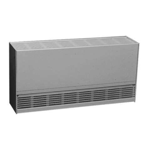
Type CKH — Kick Space Heater
INSTALLATION
Specifications –
Model Volts Watts Phase BTUH Weight Stock PCN
(Lbs.)
120 450 1 1534 14.0 S 352313
3.8 Amps
120 900 1 3071 14.0 S 352313
7.5 Amps
120 1350 1 4606 14.0 S 352313
11.3 Amps
120 1800 1 6142 14.0 S 352313
CKH-20F31 15 Amps
208 675 1 2303 14.0 S 352313
3.2 Amps
208 1350 1 4606 14.0 S 352313
6.5 Amps
240 900 1 3071 14.0 S 352313
3.8 Amps
240 1800 1 6142 14.0 S 352313
7.5 Amps
Optional Accessories –
24-1/8
4-1/2
7/8" Dia. K.O. (2 pts.)
1-3/4
2
1
3-1/2 1-3/4
Back View
22-1/8
Wiring
Junction Box 9-1/2
13
578
46
2
Safety Switch
Service Wires
Fan
GND
13
578
46
2
Safety Switch
Service Wires
Fan
GND
13
578
46
2
Safety Switch
Service Wires
Fan
GND
Factory Connection 208/240V 675/900W
May be field 120V 450, 900,
reconnected to 1350, 1800W
208/240V 1350/1800W
Electrical Inspection —
Remove grille, screen and frame by removing screws “A”.
Remove screws “C” at front of junction box. The junction box cover
can now be removed through the front opening, and field wiring can
be observed. When re-assembling, reverse the procedure above.
Cleaning —
WARNING: Hazard of Severe Shock. Disconnect all
power to heater before servicing.
With Grille in Place :
Use vacuum cleaner hose to suck out lint and dirt around grille.
Reverse hose on vacuum to use as a blower to move dust out of enclo-
sure. Reverse hose back to suck out dirt at front area of heater.
With Grille Removed :
Remove two screws “B” at bottom front of heating element assembly.
Pull gently on assembly to remove it from the enclosure. Swing assem-
bly out. Vacuum inside of enclosure and around heating element
assembly. Reverse procedure above to re-assemble unit.
Note 1: Care must be taken to prevent undue strain on all wiring or
heating element assembly, when removing and re-assembling
heating element assembly.
Note 2: For field rewiring to 120V, all leads must be secured under
wire clamps.
Note 3: Air and grille temperatures may discolor certain materials,
particularly those materials incorporating clear vinyl.
Materials should be checked prior to installation to determine
if discoloration or distotion would occur in the vicinity of
140˚F (60˚C).
2150 N. RULON WHITE BLVD., OGDEN, UT 84404
Phone: 1-800-368-2493 www.chromalox.com
MAINTENANCE
WARNING: Hazard of Severe Shock. Disconnect all
power to heater before servicing or replacing heaters.
Normal maintenance requires only an occasional vacuuming using
standard vacuum attachments.
WARNING: Do not block air flow in any way with
drapes, rugs or other objects.
REPLACEMENT PARTS
For replacement parts, please consult with the Product Service Center listed below.
22-3/8"
3-5/8"
3-1/2"
22" 9-1/2"
3"
Max
Knockouts
Service Cable
10" Min
Ceiling Grille
Heater
Cabinet Door Partition or
Added Support
3/4"
Min
Figure 3
Figure 2
Figure 1
Top Label
Heater Cover
Junction Box Cover
Screw “C”
Screw “A” Trim Frame
Grille
Screw “B”
Heater Element
IMPORTANT: Retighten all leads with cable
clamp after reconnecting uninsulated ends
of unused leads with wire nuts.
Rating Connect
450W 3.75A 7-8 (As Shown)
900W 7.5 A 7-8, 1-2
1350W 11.2A 7-8, 1-2, 3-4
1800W 15A 7-8, 1-2, 3-4, 5-6
208/240 Volt 675/900 Watts
(Factory Connection) 3.2A/3.7A
208/240 Volt 1350/1800 Watts
(Field Connection) 6.5A/7.5A
120V (Field Connection)
Figure 4
Limited Warranty:
Please refer to the Chromalox limited warranty applicable to this product at
http://www.chromalox.com/customer-service/policies/termsofsale.aspx.

This manual suits for next models

1

Other Chromalox Heater manuals

Chromalox ADH-005 User manual

Chromalox

Chromalox ADH-005 User manual

Chromalox HVH-02-81 User manual

Chromalox

Chromalox HVH-02-81 User manual

Chromalox CAF-6 User manual

Chromalox

Chromalox CAF-6 User manual

Chromalox ICH-18025 User manual

Chromalox

Chromalox ICH-18025 User manual

Chromalox V-2020 User manual

Chromalox

Chromalox V-2020 User manual

Chromalox HD3D Manual

Chromalox

Chromalox HD3D Manual

Chromalox NOR FOUND PD445 User manual

Chromalox

Chromalox NOR FOUND PD445 User manual

Chromalox PF490-5 User manual

Chromalox

Chromalox PF490-5 User manual

Chromalox UB-2502A User manual

Chromalox

Chromalox UB-2502A User manual

Chromalox UB-1002E User manual

Chromalox

Chromalox UB-1002E User manual

Chromalox STAR-02A-11-F User manual

Chromalox

Chromalox STAR-02A-11-F User manual

Chromalox HVH Series User manual

Chromalox

Chromalox HVH Series User manual

Chromalox UB-23E Guide

Chromalox

Chromalox UB-23E Guide

Chromalox V-2020 User manual

Chromalox

Chromalox V-2020 User manual

Chromalox PF411-10 User manual

Chromalox

Chromalox PF411-10 User manual

Chromalox SDRA-30-43 User manual

Chromalox

Chromalox SDRA-30-43 User manual

Chromalox CXH-A/B-03S Manual

Chromalox

Chromalox CXH-A/B-03S Manual

Chromalox CAF-12 Installation and operating instructions

Chromalox

Chromalox CAF-12 Installation and operating instructions

Chromalox ADH-005 User manual

Chromalox

Chromalox ADH-005 User manual

Chromalox CAF-20215 Installation and operating instructions

Chromalox

Chromalox CAF-20215 Installation and operating instructions

Chromalox CXH-A-03 User manual

Chromalox

Chromalox CXH-A-03 User manual

Chromalox PF479-6 User manual

Chromalox

Chromalox PF479-6 User manual

Chromalox TM Series Manual

Chromalox

Chromalox TM Series Manual

Chromalox PF451-3 User manual

Chromalox

Chromalox PF451-3 User manual

Popular Heater manuals by other brands

BN Thermic HB-1500 instructions

BN Thermic

BN Thermic HB-1500 instructions

Somogyi home FK 24 instruction manual

Somogyi

Somogyi home FK 24 instruction manual

Currys Essentials C7MOR12 instruction manual

Currys Essentials

Currys Essentials C7MOR12 instruction manual

Helo Ring1118-600-0405 Installation and user manual

Helo

Helo Ring1118-600-0405 Installation and user manual

Bimar S580.CH Instruction booklet

Bimar

Bimar S580.CH Instruction booklet

BIEMMEDUE SD 70 manual

BIEMMEDUE

BIEMMEDUE SD 70 manual

VEAB VFLPG manual

VEAB

VEAB VFLPG manual

Melchioni MAGMA user manual

Melchioni

Melchioni MAGMA user manual

GET G4HAL instructions

GET

GET G4HAL instructions

Dimplex Heater user guide

Dimplex

Dimplex Heater user guide

Powell RHS-40 user guide

Powell

Powell RHS-40 user guide

Sygonix EJ1116 user manual

Sygonix

Sygonix EJ1116 user manual

Tradgardsteknik TMT30 Installation and maintenance manual

Tradgardsteknik

Tradgardsteknik TMT30 Installation and maintenance manual

Go 1098T owner's manual

Go

Go 1098T owner's manual

ACV E-Tech M 36 FLEX Procedure

ACV

ACV E-Tech M 36 FLEX Procedure

Alliance Products DALPH1002 Operation manual

Alliance Products

Alliance Products DALPH1002 Operation manual

Mercury 450.010UK user manual

Mercury

Mercury 450.010UK user manual

Panasonic FY-08ESN operating instructions

Panasonic

Panasonic FY-08ESN operating instructions

manuals.online logo
manuals.online logoBrands
  • About & Mission
  • Contact us
  • Privacy Policy
  • Terms and Conditions

Copyright 2025 Manuals.Online. All Rights Reserved.