Chtce ZHRV2-54T User manual
R
Operating Instruction of ZHRV2-54T Digital Household Self-resetting Overvoltage and Undervoltage Protector
-1-
Built-in high-performance microcontroller, with high
reliability and strong antijamming capability.
LED Nixie tube displaying the operating voltage value.
Featuring with overvoltage and undervoltage protective function.
User can set the protection parameters by using the buttons.
Voltage measuring accuracy≤1%.
Measuring frequency: 45Hz-65Hz.
It can be installed on standard rail 35mm.
Functions and features
Model and meaning
Main technical parameters
Rated supply voltage
AC100V~400V
AC220V
Rated supply frequency
Overvoltage actuation time
Undervoltage
actuation time
50/60Hz
0.1s
120~200V,1s
<120V,<0.1s
5V
Voltage measuring error
≤1% (entire setting range)
Delay error
±10%+0.1s
Measuring accuracy
1%, true virtual value measurement
Rated insulation voltage 415V
Permissible relative humidity ≤50% (40℃) (without condensation)
Storage temperature -25℃~55℃
Model and maximum NT00-6A
Pollution level
Protection class
3
IP20
Electrical life
10 5
Mechanical life 6
10
Altitude ≤2000m
Operating ambient -5℃~40℃
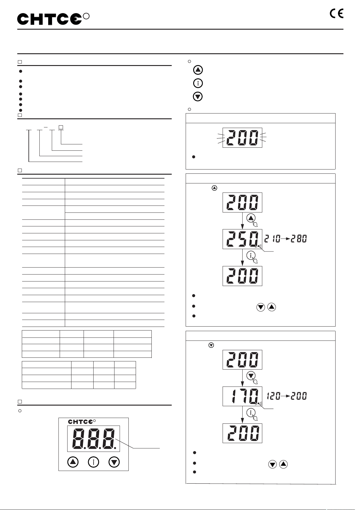
○ Panel schematic diagram
Setting of overvoltage operating value
Example
Rated operational voltage
Voltage lagged value
Setting of overvoltage operating value/digit+ button
ZH
Rated operational current: 50A, 63A,80A
Protection model
RV2 54T
Enterprise code
Voltage protection
Current specification
50A 63A 80A
50A
10kW
63A 80A
13kW 17kW
Rated operating frequency
Maximum operating current
(within 10min)
Maximum cross-section
of conductor 16mm2
Operating instructions of button menu
Confirm modification button
Setting of Undervoltage operating value/digit- button
Button explanation
Long press for 3s
Confirm modification
The relay will automatically quit the menu and not save the modified
data if not operating the button for continuous 60s during setting
parameters.
It can change the setting value by pressing
The rightmost indication point flickers after entering overvoltage setting interface.
Flickers
Long press
Long press
Setting of Undervoltage operating value
Long press for 3s
16mm 16mm
2 2
Technical parameters
Setting range
Stepping amount Factory set value
Overvoltage operating value
210V~280V
120V~200V
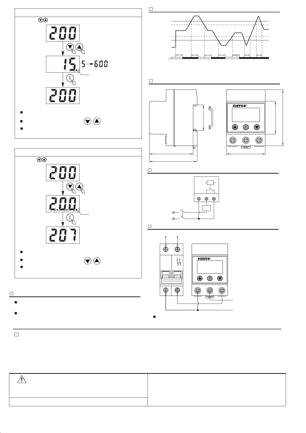
5s~600s
1V
1V
5s
250V
170V
15s
Breakover delay time
Breakover delay display
Operating voltage value of LED Nixie tube flickers during breakover
delay; operating voltage value of LED Nixie tube will be normally on
after delay is over and output relay is with breakover.
LED Nixie tube
Flickers
Confirm modification
The relay will automatically quit the menu and not save the modified
data if not operating the button for continuous 60s during setting
parameters.
It can change the setting value by pressing
The rightmost indication point flickers after entering Undervoltage
setting interface.
of short circuit protector
rating
temperature
Undervoltage operating value for 3s to enter setting interface of Undervoltage operating value:
for 3s to enter setting interface of Undervoltage operating value:
R
Conform to:IEC60947-5-1standard
It can change the setting value by pressing
-2-
Danger warning
Please operate with outage during installation and wiring.
- Please confirm that the supply voltage confirms to the rated supply voltage
of the product before wiring.
It is possible to cause electric shock or fire if the above is not observed.
Electrical diagram
Shape and dimension
Function sequence diagram
N
1 2 3
L
Tel: 86-577-61786218 61786228
Fax: 86-577-61786128
http://www.chtce.com http://www.chtce.cn
Address: ShangWuzhai Village, Liushi Town, Yueqing City, Zhejiang Province
Long press for 3s
Confirm modification
The relay will automatically quit the menu and not save the modified
data if not operating the button for continuous 60s during setting
parameters.
The rightmost indication point flickers after entering setting interface of
breakover delay time.
It can change the setting value by pressing
Flickers
Setting of breakover delay time
Long press for 3s
Confirm modification
The relay will automatically quit the menu and not save the modified
data if not operating the button for continuous 60s during setting
parameters.
The three indication points flicker after entering voltage value
calibration interface.
Flickers
Voltage value calibration
Operating value -5V
Operating value +5V
Undervoltage operating value
U
To Tu <Tu <To
Overvoltage operating value
Tr Tr Tr
Relay
Tr: Breakover delay time
Precautions
R
54
35.5
77
60
65.5
1 2 3
45
If there is voltage fault while power on after the breakover delay of relay
completes, the output relay will not operate.
LED Nixie tube will display the operating voltage value after the relay
normally operates.
Operating instructions
LOAD
MCB
Wiring diagram
3
1
24
O-OFFO-OFF
Fire wire
Null line
R
1 2 3
N L
N
L
Connected load
Rated operating current of circuit breaker is 75% maximum current of voltage relay.
I e = 0 . 7 5 I m a x
Long press both
Long press both
for 3s to enter setting interface of breakover delay time:
for 3s to enter voltage value calibration interface before the relay is energized:
7. Please store and use the product under rated supply voltage and the stipulated temperature, altitude and humidity.
6. The product is prohibited to be used in medium with explosion hazard, which medium shall not contain corroding metal, gas destroying insulation and conducting dust.
5. It is prohibited to use the product in places with dustiness, corrosive gas, direct sunlight or rain.
4. Power incoming line is prohibited for wiring in the same tube with other electric wires of strong current. And please use shielded wire if necessary to avoid interference and influencing the normal
3. Please refer to the wiring diagram for wiring.
2. The user is prohibited to take apart or maintain the product regardless of whether the product is normal or damaged, otherwise our company will not assume any liability for any accident caused.
1. The installation, operation and overhaul of this product shall be carried out by a professional. The product warranty period is 18 months under regular service condition.
operation of the protector.
CHTCE Technology Co., Ltd.
Tu: Undervoltage operating delay time
To: Overvoltage operating delay time
Popular Surge Protector manuals by other brands


Ilsco
Ilsco SSI SpecPRO SSM 28 Series manual

SolarEdge
SolarEdge SE-RS485-SPD2-K2 installation guide

APT
APT TEHP Series Installation, operation & maintenance manual

Ilsco
Ilsco SSI SpecPRO CRM 12 Series manual

Emerson
Emerson SolaHD STC-HSP Series manual

Bretford
Bretford Powerbar 35PBCFPS Assembly instructions