Churchill ION User manual

ION
InstallationManual
Rev.1.6

Churchill Navigation Support ●Phone: 720.744.3300 ●E-mail: support@churchillnavigation.com 2
Rev
Number
Description
Date
1.0
1.1
1.2
1.3
1.4
1.5
1.6
Original document release
Minor content revisions, updated installation drawings
Audio information, updated installation drawings, and updated text
description based on new installation drawings. Added change
tracking (black lines in margin)
Minor text updates
Updated audio pin-outs, Installation diagram supplement added
Added additional specifications for analog video
Grounding requirements updated, misc. other updates
NOV 2015
DEC 2015
JUN 2016
SEP 2016
DEC 2016
JAN 2017
JUN 2017

Churchill Navigation ●Support Phone: 720.744.3300 ●E-mail: support@churchillnavigation.com 3
Table of Contents
About this Manual ............................................................................................................... 4
Product Guarantee & Warranty Information ........................................................................ 4
Section 1: Specifications....................................................................................................... 5
1.0 Description........................................................................................................................... 5
1.1 Design Characteristics.......................................................................................................... 5
Section 2: Installation Guidelines ......................................................................................... 8
2.0 Description........................................................................................................................... 8
2.1 Equipment Packaging........................................................................................................... 8
2.2 Required Tools ..................................................................................................................... 8
2.3 Installation ........................................................................................................................... 9
Section 3: Aircraft Post-Installation Testing Procedures ...................................................... 14
Section 4: Installation Diagrams .......................................................................................... 17

Churchill Navigation ●Support Phone: 720.744.3300 ●E-mail: support@churchillnavigation.com 4
Notice:
The information contained in this document is considered confidential and proprietary to Churchill
Navigation. Neither the document nor the information contained therein should be disclosed or
reproduced in whole or in part, without express written consent of Churchill Navigation.
Changes or modifications not expressly approved by Churchill Navigation could void the user’s
authority to operate the equipment.
Non-Churchill Navigation part numbers referenced in this manual are not maintained by Churchill
Navigation and may be subject to change without notice.
All information depicted in this manual, including hardware and software names, versions, and part
numbers, is subject to change and may not be up to date.
About this Manual
This manual describes the physical, mechanical, and electrical components, as well as instructions for
the installation of the Churchill Navigation ION. Every effort has been made to make this document as
complete and accurate as possible.
The following symbols for warnings, cautions, and notes are used to throughout this manual.
Warning
A warning symbol denotes an item where a potential hazard capable of
producing injury to personnel or destruction of equipment exists if the
approved procedure is not followed.
Caution
A caution symbol denotes an item where, if not followed, damage to
equipment or degradation of mission capability can occur.
Note
The note symbol is used to identify important information for installers /
operators. While not directly related to safety or protection of equipment from
damage, the note symbol identifies information to which attention should be
paid during the installation and/or operation of the equipment.
Product Guarantee & Warranty Information
For details about the Churchill Navigation ION warranty, please see the Terms and Conditions page
available at www.churchillnavigation.com/agreement
!
!

Churchill Navigation ●Support Phone: 720.744.3300 ●E-mail: support@churchillnavigation.com 5
Section 1: Specifications
This document contains information that was current as of the printing of this manual. To obtain
always up-to-date installation drawings, ICDs, and much more, visit:
www.churchillnavigation.com/specifications
1.0 Description
This section contains information concerning the physical characteristics and technical specifications of
the Churchill Navigation ION video recorder.
1.1 Design Characteristics
ION is a compact, solid-state DZUS mounted video recorder. ION offers simultaneous recording of two
channels of HD-SDI video, one channel of analog video, audio, and metadata. Video is saved to
removable USB or SD media for easy transport and hand-off. A full-color, backlit LCD display allows
operators to review recorded clips on the go and even perform playback while recording.
1. Backlit, full-color, 2.15 in [54.61 mm] diagonal LCD screen
2. Backlit REC button
3. Backlit Mute button
4. Control knob (inner knob, outer knob, and push-button operation)
5. SD media (2x)
6. USB 3.0 (2x)
7. Fault light
8. CMOS Battery access tray (located on the bottom of the enclosure) *
* CMOS battery access tray included on ION hardware revision 2.8 and higher.
8
Specifications
1
7
2
3
4
6
5

Churchill Navigation ●Support Phone: 720.744.3300 ●E-mail: support@churchillnavigation.com 6
1.2 Technical Characteristics & Specifications
Specification
Characteristic
Product Designation/Description
ION Video Recorder
Physical Dimensions
Height at bezel: 1.875 in [47.63 mm]
Width at bezel: 5.75 in [146.05 mm]
Length (Enclosure depth): 7.0 in [177.8 mm]
Overall depth, front knob to back of enclosure, excluding
connectors: 8.32 in [211.33 mm]
Weight
2.6 lbs ± .05 lbs [1.18 kg ± .02 kg]
Display type / dimensions /
resolution
Backlit LCD, 2.15 in [54.61 mm] diagonal
Native 320 x 240 pixel resolution
NVIS Class A compliant / NVIS class B compatible
Environmental Qualifications
DO-160 Qualified
Operating Temperature Range
-20°C to +70°C
Maximum Operating Altitude
+45,000 feet [+13,716m]
Power:
Input Voltage
Input Current
Power consumption
28VDC
4A on 28VDC (normal operating range)
112W (maximum)
Circuit Breaker Requirement
Minimum 7.5 amp rated
Connection Types, Protocols, and
Standards
LEMO (1x) J1 – Power/GPIO
LEMO (1x) J2 – Ethernet
LEMO (1x) J3 – Misc. (USB, ARINC 429, Audio)
LEMO (1x) J4 – Serial port (RS232, RS422)
BNC J5, J6, J7 – HD-SDI 1 & HD-SDI 2 video in /
HD-SDI video out
BNC J8, J9, J10 – Analog in
Wi-Fi compatibility – 802.11ac
Video-in Support
2x HD-SDI inputs
- Single channel, 3G-SDI (1080p60) input supported
1x Analog video input (CVBS, Y/C, YPbPr, & RGB)
Video-out Support
1x HD-SDI output
- 3G-SDI (1080p60) output supported
Specifications

Churchill Navigation ●Support Phone: 720.744.3300 ●E-mail: support@churchillnavigation.com 7
Video-out Supported Resolutions
720p (50 fps), 720p (60 fps), 1080p (25 fps), 1080p (30 fps)
1080p (60 fps), 1080i (50 fps), 1080i (60 fps)
Metadata Standard
KLV MISB/STANAG 4609 compliant
Video Recording Codec
H.265 (HEVC) – Skylake processor models only
H.264 (MPEG-4)
H.262 (MPEG-2)
Audio-in Support
L/R channel in
Audio-out Support
L/R channel out
Specifications

Churchill Navigation ●Support Phone: 720.744.3300 ●E-mail: support@churchillnavigation.com 8
Section 2: Installation Guidelines
2.0 Description
This section contains information and instructions for the unpacking and correct installation of the
Churchill Navigation ION video recorder.
2.1 Equipment Packaging
Prior to installation, carefully inspect both the ION unit and the supplied power connector. Note any
damage that may have occurred in transit and contact the parcel carrier if necessary to file a claim.
Otherwise, check that all items listed below are present prior to proceeding with the installation. Report
any missing items to your supplier.
-(1) ION
-(1) ION power connector (p/n FGN.1M.308.XLCT)
-(2) SD Cards (32GB each)
-Product manuals and guides
It is recommended that you retain all original packaging for purposes of easy returns due to
damage or warranty claims.
All other connectors are available for purchase from Churchill Navigation or direct from the
manufacturers themselves. Additional information is provided in section 2.3 of this guide. If you have
purchased additional hardware, such as the ION Connector Kit, from Churchill Navigation, please take a
moment to inspect the condition of those connectors as well prior to starting the installation process.
2.2 Required Tools
You will need the correct crimping tool for the connectors selected. A few examples are listed below
and are available from Churchill Navigation or from their respective manufacturers.
BNC Connectors:
Application
Connector:
Crimp Die:
75ohm BNC plug for PICWire V73263
PicWire P/N 190712
M22520/5-41
75ohm BNC plug for RG59
Amphenol P/N 112123
.255/.213/.068
75ohm BNC plug for RG179
Amphenol P/N 112133
.178/.128/.068
All LEMO Connectors:
Crimp Tool
Pin Positioner
Pin Extractor
DPC.91.701.V
DCE.91.070.5MVC
DCF.93.070.4LT
Installation

Churchill Navigation ●Support Phone: 720.744.3300 ●E-mail: support@churchillnavigation.com 9
2.3 Installation
ION is intended for DZUS mount (or similar) installations. If you are unsure of the installation location,
please contact Churchill Navigation.
To ensure adequate airflow to the unit, Churchill Navigation recommends a minimum of 100mm
between the back of the ION and any adjacent surface.
The minimum ION installation requires 28VDC power and at least one type of supported video input.
Additionally, some operators may wish to include audio-in as a part of their basic setup. The
corresponding Installation Manual sections required for minimum operation as described above are:
1) Power – Sections 2.3.1, 2.3.2, and 2.3.3.1
2) Video – Section 2.3.3.5 (HD-SDI) and Section 2.3.3.6 (Analog)
3) Optional audio-in – Section 2.3.3.3
Support for these as well as all other inputs and features are described in detail in the following sections
of this guide.
2.3.1 Voltage Requirements
ION operates on 28-volt DC power and consumes a maximum of 112 watts (4 amps on 28VDC).
Churchill Navigation recommends using a minimum 7.5-amp circuit breaker.
2.3.2 Ground Requirements
ION IS CASE-GROUNDED THROUGH THE DZUS MOUNT. If the DZUS mount is not directly grounded
to the chassis, use a minimum of 16-gauge wire to ground the DZUS mount prior to ION operation.
EXPOSED ALUMINUM IS CHROMATED. DO NOT CHEMICALLY COAT OR COVER WITH NON-
CONDUCTIVE MATERIAL.
ALL GROUND PINS EXCEPT 28V RETURN ARE GROUND CONTINUOUS TO CASE.
Failure to properly ground the ION unit may result in damage to the ION as well
as possibly other installed equipment.
2.3.3 Cabling requirements
To ensure a properly functioning ION, the following cabling requirements are highly recommended.
Any variation will be at the sole responsibility of the dealer or installer. Detailed installation
diagrams are provided in Section 3 of this manual.
Install each cable with an 8 inch [203 mm] service loop to allow for easy servicing of the
ION unit.
2.3.3.1 Power (J1)
Each ION is shipped with a circular LEMO 8-pin male connector, P/N FGN.1M.308.XLCT to be
Installation
!
Churchill Navigation ●Support Phone: 720.744.3300 ●E-mail: support@churchillnavigation.com 10
used as the power connector. If you wish to use a different power connector, the connection to
28VDC input on the ION and 28VDC GND are highly recommended to be a twisted pair. Use of
22 AWG wire size is recommended. J1 also contains provisions for GPIO1 and GPIO2 and aircraft
panel dimmer brightness control.
Pin
Function
Description
1
28V
Connect to 28V power source
2
28V GND
Ground for 28V power source
3
Panel Brightness
Panel brightness can be wired to aircraft cockpit dimmer
knob and has a maximum voltage input of 30V
4
Panel Brightness GND
Ground for panel brightness
5
GPIO 1
GPIO
6
GPIO 1 GND
GPIO Ground
7
GPIO 2
GPIO
8
GPIO 2 GND
GPIO Ground
2.3.3.2 Ethernet (J2)
Churchill Navigation recommends using either PicWire PIC E50824 or EMTEQ D100-0824-006 4-
pair Ethernet cable. Both can be purchased from Churchill Navigation or directly from their
respective manufacturers at http://www.picwire.com or http://www.emteq.com Use the
connection labeled “J2 - Ethernet”. Twisted pair is indicated by color block.
Pin
Function
Wire color
1
TX-/BiD1-
Orange
2
TX+/BiD1+
Orange/White
3
RX-/BiD2-
Green
4
RX+/BiD2+
Green/White
5
BiD4-
Brown
6
BiD4+
Brown/White
7
BiD3-
Blue
8
BiD3+
Blue/White
2.3.3.3 Misc. (J3) – USB, Audio, ARINC
J3 contains connection provisions for Audio in/out, ARINC and USB connectivity. Twisted pairs are
indicated by color block and noted in the “pair with” column.
Pin
Function
Description
Pair with
1
AUDIO OUT L
Audio-out, left channel
--
2
AUDIO IN R HIGH
Audio-in, right channel
--
3
AUDIO IN L HIGH
Audio-in, left channel
--
4
USB 5V
USB 5V
--
5
USB +*
USB +
--
6
USB -*
USB -
--
7
ARINC TX1-*
ARINC transmit 1-
ARINC TX1+
8
ARINC RX2-*
ARINC receive 2-
ARINC RX2+
9
ARINC RX2+*
ARINC receive 2+
ARINC RX2-
10
ARINC RX1-*
ARINC receive 1-
ARINC RX1+
(Table continued next page)
Installation

Churchill Navigation ●Support Phone: 720.744.3300 ●E-mail: support@churchillnavigation.com 11
11
ARINC RX1+*
ARINC receive 1+
ARINC RX1-
12
AUDIO OUT R
Audio-out, right channel
--
13
AUDIO IN R LOW
--
14
AUDIO IN L LOW
--
15
USB GND
Ground
--
16
ARINC
ARINC Ground
--
17
ARINC TX1+*
ARINC transmit 1+
ARINC TX1-
18
AUDIO OUT GND
Audio Out Ground
--
19
GND
Ground
--
*Twisted pair required.
For USB applications using J3, Churchill Navigation recommends the following:
Option A: Carlisle 28433/02171LX-4. This cable can be purchased directly from Carlisle:
http://www.carlisleit.com
Option B: EMTEQ U090-0422-100: This cable can be purchased directly from Emteq:
http://www.emteq.com
USB performance cannot be guaranteed at cable lengths greater than 10ft (3.04m)
without the use of an extender. Contact Churchill Navigation for additional information.
Aircraft Audio Setup Recommendations:
For best audio quality, Churchill Navigation recommends that the ION audio input be connected to
a balanced (chassis ground independent) output, with -15 dBV signal levels. It is also
recommended to connect the ION audio input to a COM port, rather than a headset output.
To connect an unbalanced audio signal, ensure that the ground signal from the audio source is
shorted to ground at the source. This ground of the audio signal should then be connected to pins
13 and 14 of J3 on the Ion.
The recommended ION audio setup has been tested on common aircraft audio control systems
including the Eagle Copters USA (Geneva Aviation) G13000 Digital Audio Router and Technisonic
A711 and A711X. If you have questions regarding the best audio setup for your installation, please
contact Churchill Navigation.
ION can be configured to record stereo audio as two separate channels; ICS as channel 1
and RX/TX (Comm) as channel 2, for example. To do this, separate audio-in via J3 pin 2
and pin 3.
2.3.3.4 Serial Com (J4) – RS232, RS422
J4 contains connection provisions for RS232 and RS422 serial communications. Twisted pairs are
indicated by color block and noted in the “pairing” column.
The maximum speed for cable runs of less than 25 feet [7.62m] is 256 kbit/s for
!
!
Installation

Churchill Navigation ●Support Phone: 720.744.3300 ●E-mail: support@churchillnavigation.com 12
RS232 and 8 Mbit/s for RS422.
Pin
Function
Description
Pair with
1
RS232C TX
RS232C transmit from ION
--
2
RS232C RX
RS232C receive to ION
--
3
RS232A TX
RS232A transmit from ION
--
4
RS232A CTS
RS232A Clear to Send
--
5
RS232B TX
RS232B transmit from ION
--
6
RS232B RX
RS232B receive to ION
--
7
RS232B RTS
RS232B Request to Send
--
8
RS422A RX-*
RS422A receive to ION -
RS422A RX+
9
RS422A TX-*
RS422A transmit from ION -
RS422A TX+
10
RS422A TX+*
RS422A transmit from ION +
RS422A TX-
11
RS422B RX+*
RS422B receive to ION +
RS422B RX-
12
RS422B TX+*
RS422B transmit from ION +
RS422B TX-
13
RS232D TX
RS232D transmit from ION
--
14
RS232D RX
RS232D receive to ION
--
15
RS232E RX
RS232E receive to ION
--
16
RS232E TX
RS232E transmit from ION
--
17
GND RS232C
Ground (RS232C TX/RX)
--
18
RS232A RX
RS232A receive to ION
--
19
RS232A RTS
RS232A Request to Send
--
20
GND RS232B
Ground (RS232B TX/RX)
--
21
RS232B CTS
RS232B Clear to Send
--
22
RS422A RX+*
RS422A receive to ION +
RS422A RX-
23
RS422B RX-*
RS422B receive to ION -
RS422B RX+
24
RS422B TX-*
RS422B transmit from ION -
RS422B TX+
25
GND RS232D
Ground (RS232D TX/RX)
--
26
GND RS232E
Ground (RS232E TX/RX)
--
27
GND
Ground (Extra)
--
28
GND RS232A
Ground (RS232A TX/RX)
--
29
GND RS422A
Ground (RS422A TX/RX)
--
30
GND RS422B
Ground (RS422B TX/RX)
--
*Twisted pair required.
2.3.3.5 BNC (J5, J6, J7) – 75 Ω HD-SDI COAX Cable
ION has two HD-SDI in connections and one HS-SDI video out connection. When used with gyro-
stabilized gimbals, HD-SDI video 1 (J5) is typically used for Video In Command, HD-SDI video 2 (J6)
is typically used for a hoist camera, etc. All BNC connectors use the center pin for the signal and
the shell as the ground.
In almost all applications, Churchill Navigation recommends use of PicWire PIC V73263 lightweight
75ohm coaxial cable, P/N 190712, available from Churchill Navigation or http://www.picwire.com
If an installation requires alternative cabling, please use the following:
Installation
Churchill Navigation ●Support Phone: 720.744.3300 ●E-mail: support@churchillnavigation.com 13
Alternative A: RG59 can be used in place of PicWire PIC V73263. The proper connector is
Amphenol Connex 112123. These are available from Churchill Navigation or
http://www.digikey.com
Alternative B: If RG179 is required by other equipment (ex. MX-10 gimbal), then for EMI
purposes, DOUBLE high performance 360 degree EMC individual braid shielding must be done to
RG179 cable from end to end. The proper connector is Amphenol Connex 112133, available
from Churchill Navigation or http://www.digikey.com
2.3.3.6 BNC (J8, J9, J10) – Analog video
ION is capable of recording from composite or component video sources. PAL, NTSC, S-Video, RS-
170, and component-in are supported. The following configurations are allowed:
Composite Video In
(CVBS)
S-Video In
Component Video In
(YUV)
Component Video In
(RGB)
J8
J8-Luma (Y)
J9-Chroma (C)
J8-Luma (Y)
J9-Blue Chroma (Pb)
J10-Red Chroma (Pr)
J8-Green (SYNC)
J9-Blue
J10-Red
For all BNC connectors, the center conductor pin is the signal and the shell is the
ground.
Supported Analog Video Types
ION supports input from the following analog video types:
−Composite
−S-Video
−Component_YUV_480i
−Component_RBG_480i
−Component_YUV_576i
−Component_RBG_576i
−Component_YUV_480p
−Component_RBG_480p
−Component_YUV_576p
−Component_RBG_576p
2.3.3.7 All Other Cables
Other cables can be selected at the installer’s discretion to meet the needs of the installation.
All cables MUST BE SHIELDED. This includes power cables.
!
Installation
!

Churchill Navigation ●Support Phone: 720.744.3300 ●E-mail: support@churchillnavigation.com 14
Section 3: Aircraft Post-Installation Testing Procedures
3.0 Description
The following tests should be performed post-installation to confirm the correct operation of the ION
video recorder in airborne applications. Additionally, these tests will identify any interference that the
ION installation may cause with existing aircraft systems. If the installed system passes all of the
applicable EMI tests, then no further action is required. If interference is observed, then the interference
must be assessed against the appropriate standards of airworthiness for the system in question.
3.1 Methodology
Most EMI tests can be conducted on the ground unless otherwise noted. Testing recommendations for
various aircraft system tests are provided below. During all tests, it is recommended that users switch
the ION unit on and off as often as required to evaluate potential EMI in all phases of ION operation.
ADF
If possible set the ADF to a nearby navigation station and monitor for interference.
Autopilot
If the aircraft is equipped with an autopilot or a stability augmentation system, test
fly the aircraft and verify that operation of the ION does not have adverse effects on
these systems.
GPS
The GPS should be operational and navigating with at least the minimum
compliment of satellites.
Observe the GPS for any degradation in satellite status, loss of RAIM, or warning
messages/flags.
Transponder
The transponder and encoder should be monitored with ramp test equipment. Set
the output of the transponder test set to 3db above the output necessary to
achieve 90% reply.
VHF Comm
Radio
The VHF comm radio should have the squelch open.
Listen for any noise or detected audio signals on the VHF comm radio(s).
Navigation
Radios
Operation of the Navigation radios (VOR/LOC/GS/DME receiver(s)) should be tested
using known operational facilities.
Listen for any noise or detected audio signals on the VOR/LOC/GS receiver audio;
look for any moment of flags or needles on the VOR/LOC/GS navigation display(s).
Testing Procedures

Churchill Navigation ●Support Phone: 720.744.3300 ●E-mail: support@churchillnavigation.com 15
3.2 Power-on Checks
Prior to performing any other tests, the user should confirm the basic operation of the ION unit. This can
be conducted using ground power or in-air using aircraft power.
1) Power the ION on and confirm the boot sequence.
2) With either USB or SD removable media inserted, use the outer knob to select a video channel
from which you want to record and press the REC button. Ensure no faults.
3) End recording by pressing the REC button a second time.
4) Playback recorded video using:
a. The ION unit’s on-screen playback capability, or
b. The removable media by inserting it into a Windows PC or Macintosh computer and
playing back the recorded .TS file. Churchill Navigation recommends using the VLC
Player available from videolan.org for playback if you encounter any difficulty playing
files back with your normal media player.
If unable to successfully complete any of these steps, begin by rechecking wiring, connections, and if
necessary, contact Churchill Navigation Support for further troubleshooting.
3.3 EMI Test
List the power plant, fuel, and other electric instruments not already in the chart provided and note any
anomalies that occur due to operation of the ION. Assess the results.
Aircraft communications & navigation equipment tests
Pass/Fail
Com 1&2
Transponder &
Encoder
ADF 1 & 2
Glideslope 1&2
VOR/LOC 1&2
DME 1&2
Compass
Directional Gyro
GPS
Digital Clock
Autopilot tests
Pass/Fail
Autopilot
(Table continued next page)
Testing Procedures

Churchill Navigation ●Support Phone: 720.744.3300 ●E-mail: support@churchillnavigation.com 16
Coupled Approach
Stability Augmentation
Systems
Aircraft engine systems tests
Pass/Fail
Fuel Pressure
Oil Temperature
Amps
Bus Voltage
Fuel %
Ng
TOT
Torque %
Annunciators
Oil Pressure
Other systems tests (as identified by the user)
Pass/Fail
Testing Procedures

Churchill Navigation ●Support Phone: 720.744.3300 ●E-mail: support@churchillnavigation.com 17
Section 4: Installation Diagrams
The following pages contain the installation diagrams and specific notes for the ION that were current as of
the printing of this manual. To obtain always up-to-date installation drawings, ICDs, and much more, visit:
www.churchillnavigation.com/specifications
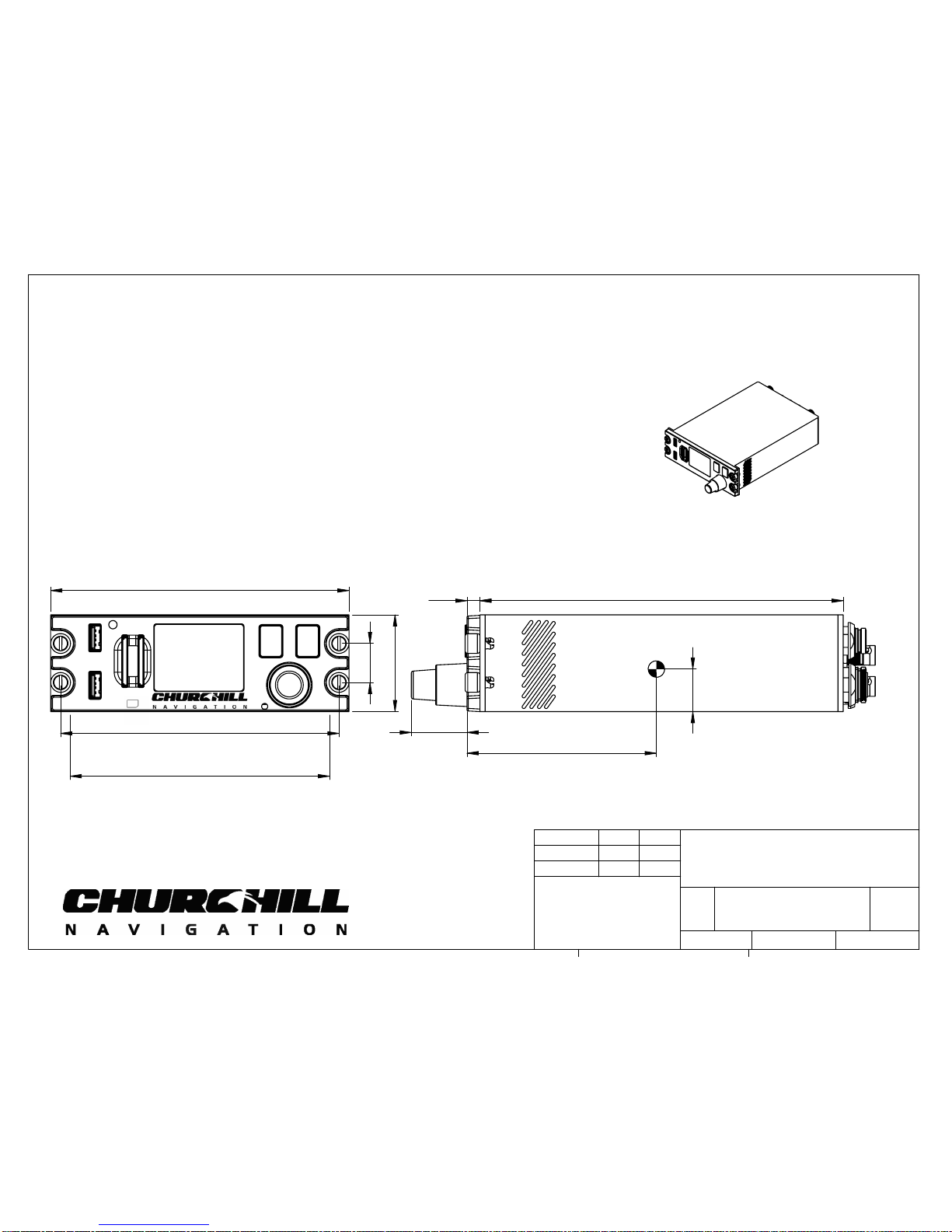
5.75
1.875
5.365
0.75
5.00
1.07
0.25 7.00
3.65
0.82
REC
MUTE
SYSTEM WEIGHT: 2.6 lbs [1.22 kg]
±.05 lbs [0.02 kg]
1 2
INSTALLATION NOTES:
ION IS CASE GROUNDED THROUGH DZUS MOUNT. IF THE DZUS
1.
MOUNT IS NOT DIRECTLY GROUNDED TO THE CHASIS, USE A
MINIMUM OF 16-GAUGE WIRE TO GROUND THE DZUS MOUNT
PRIOR TO ION OPERATION.
EXPOSED ALUMINUM IS CHROMATED. DO NOT CHEMICALLY
2.
COAT OR COVER WITH NON-CONDUCTIVE MATERIAL.
ALL GROUND PINS EXCEPT 28V RETURN ARE GROUND
3.
CONTINUOUS TO CASE.
28V INPUT IS REVERSE-POLARITY PROTECTED.
4.
RECOMMENDED POWER WIRE SIZE: 22AWG.
5.
MAXIMUM POWER DRAW IS 112 WATTS (4A ON 28VDC).
6.
FAULT
ION*
4
DO NOT SCALE DRAWING
2.2
SHEET 1 OF 7
5/18/17
NHM
JLH
REV
HARDWARE REVISION:
A
SIZE
TITLE:
NAME
DATE
CHECKED
DRAWN
5
3
2
1
PROPRIETARY AND CONFIDENTIAL
THE INFORMATION CONTAINED IN THIS
DRAWING IS THE SOLE PROPERTY OF
CHURCHILL NAVIGATION. ANY
REPRODUCTION IN PART OR AS A WHOLE
WITHOUT THE WRITTEN PERMISSION OF
CHURCHILL NAVIGATION IS
PROHIBITED.
ALL DIM IN INCHES [MM]
WEIGHT IN LBS [KG]
5/18/17
*Includes all Ion versions

J8 J9
J10
J5 J6 J7
COMPOSITE VIDEO IN (CVBS):
J8
S-VIDEO IN:
J8-LUMA (Y)
J9-CHROMA (C)
BNC CONNECTION:
CENTER PIN: SIGNAL
SHELL: GROUND
HD-SDI VIDEO 1 IN:
J5
HD-SDI VIDEO 2 IN:
J6
HD-SDI VIDEO OUT:
J7
COMPONENT VIDEO IN (YUV):
J8-LUMA (Y)
J9-BLUE CHROMA (Pb)
J10-RED CHROMA (Pr)
COMPONENT VIDEO IN (RGB):
J8-GREEN (SYNC)
J9-BLUE
J10-RED
For use with gyro-stabilized gimbals, HD-SDI
video 1 is typically used for Video In Command,
HD-SDI video 2 is typically used for hoist camera
J1 J2
COM
J5:HD SDI 1 IN
ETHERNET
POWER
ANALOG IN
J8,9,10
J7:HD SDI OUT
J6:HD SDI 2 IN
J4J3
MISC.
ION*
4
DO NOT SCALE DRAWING
2.2
SHEET 2 OF 7
5/18/17
NHM
JLH
REV
HARDWARE REVISION:
A
SIZE
TITLE:
NAME
DATE
CHECKED
DRAWN
5
3
2
1
PROPRIETARY AND CONFIDENTIAL
THE INFORMATION CONTAINED IN THIS
DRAWING IS THE SOLE PROPERTY OF
CHURCHILL NAVIGATION. ANY
REPRODUCTION IN PART OR AS A WHOLE
WITHOUT THE WRITTEN PERMISSION OF
CHURCHILL NAVIGATION IS
PROHIBITED.
ALL DIM IN INCHES [MM]
WEIGHT IN LBS [KG]
5/18/17
*Includes all Ion versions

J1: Power/GPIO
1.28V
2.28V GND
3.Panel Brightness
4.PB GND
5.GPIO 1
6.GPIO 1 GND
7.GPIO 2
8.GPIO 2 GND
1
2
8
3
4
6
7
12
13
19
18
6
2
3
4
5
7
8
9
10
11
14
15
16
17
1
2
8
3
4
6
6
8
7
5
5
7
J2: Ethernet
1:TX-/BiD1- (Orange)
2:TX+/BiD1+ (Orange/White)
3:Rx-/BiD2- (Green)
4:RX+/BiD2+ (Green/White)
5:BiD4- (Brown)
6:BiD4+ (Brown/White)
7:BiD3+ (Blue)
8:BiD3- (Blue/White)
J3:
1:AUDIO OUT L
2:AUDIO IN R HIGH
3:AUDIO IN L HIGH
4:USB 5V
5:USB D+
6:USB D-
7:ARINC TX1-*
8:ARINC RX2-*
9:ARINC RX2+*
10:ARINC RX1-*
11:ARINC RX1+*
12:AUDIO OUT R
13:AUDIO IN R LOW
14:AUDIO IN L LOW
15:USB GND
16:ARINC GND
17:ARINC TX1+*
18:AUDIO OUT GND
19:GND
Panel Brightness is to be
wired to aircraft
cockpit dimmer knob
and has a maximum
voltage input of 30V
*AVAILABLE ONLY ON
ION REV A
MISC.
J3 J4
J6:HD SDI 2 IN
J7:HD SDI OUT
ANALOG IN
J8,9,10
POWER
ETHERNET
J5:HD SDI 1 IN
COM
J2
J1
1
1
2
3
45
While populating LEMO
connectors, please follow
the pattern on the rear of
the male LEMO, as seen to
the left
Mating Connector
(Specifically FGN.1M.308.XLCT)
Maximum current draw
on rear USB is 1 Amp
ION*
4
DO NOT SCALE DRAWING
2.2
SHEET 3 OF 7
5/18/17
NHM
JLH
REV
HARDWARE REVISION:
A
SIZE
TITLE:
NAME
DATE
CHECKED
DRAWN
5
3
2
1
PROPRIETARY AND CONFIDENTIAL
THE INFORMATION CONTAINED IN THIS
DRAWING IS THE SOLE PROPERTY OF
CHURCHILL NAVIGATION. ANY
REPRODUCTION IN PART OR AS A WHOLE
WITHOUT THE WRITTEN PERMISSION OF
CHURCHILL NAVIGATION IS
PROHIBITED.
ALL DIM IN INCHES [MM]
WEIGHT IN LBS [KG]
5/18/17
*Includes all Ion versions
Other manuals for ION
1
Table of contents
Other Churchill GPS manuals


