Giandel PS-4000QAR User manual

MODEL: PS-4000QAR
V1.21.11

1. Use advanced micro processor to control.
2. Cooling fan with intelligent temperature control will not work in case the temperature is low.
3. With USB power supply, it can provide power for the portable device with USB port.
4000W
8000W
9.5-16V DC (rated power 12VDC)/
19-32V DC (rated power 24VDC)/
38-62V DC (rated power 48VDC)
0~ ~ ±11 120V / 220 240V AC 10%
(Subject to the label)
12V / 24V / 48V
≤Pure sine wave (THD 3%)
90%
5 VDC, Max. 2.4A
16 ± 0.5VDC / 32 ± 1VDC / 62 ± 1VDC
9.5 ± 0.5VDC / 19 ± 1DC/ 38 ± 1VDC
9.8 ± 0.3VDC / 19.6 ± 0.6VDC / 39.2 ± 1VDC
65 ± 5℃
4000W~4400W
3A (12V) / 0.6 (24V)
0~40℃
-10~45℃
512x203x171mm
10 Kg
Yes
The cooling fan on the product will not run when
start up the inverter, it will start running only when
the case temperature reaches about 40ˇ or the
load power is more than 1500W
Data
1.
Continuous power
Surge power
Input voltage range
Output voltage
DC input
Output wave form
Efficiency
USB output
Input over-voltage shutdown
Input under-voltage shutdown
Input under-voltage alarm
Over temperature protection
Over-load protection
No Load currents
Working temperature
Storage temperature
Intelligent cooling
Dimension (LxWxH)
Weight
Remot
1. INSTRUCTION
The GIANDEL Power inverter product line is used for back-up power. It converts DC
(direct current/car battery) power into AC (alternating current) power that can be used for
running a wide variety of tools and appliances under rating power. This inverter is perfect
for providing mobile power in cars, boats and work trucks. The inverter can also be
utilized as a back-up source of electricity in the event of an electrical failure or for several
off-grid applications such as camping or in your RV.
Please read this instruction manual carefully and make sure your inverter is installed
properly before using.
2. WARNING AND SAFETY
1) Read the manual before connecting this inverter and keep it for future reference.
2) While opening the product package, please check the integrity of the product and
accessories. If there is any problem, please do not use it.
3) While connecting and using for the first time, if there is smoke or explosion sound in
the product, please stop using immediately and disconnect the product from the
battery and electrical appliances. This may be caused by damage during the
transportation or due to moisture during storage in the warehouse before delivery.
Please contact your seller in time.
4) During daily use, if there is smoke or explosion sound in the product, please don’t
worry,this is due to the internal fuse protection of the product. Please do not
disassemble it by yourself. Please stop using the product immediately. Disconnect
the product from the battery and electrical appliances. Contact the seller in time and
only with seller’s agreement a hired professional personnel can disassemble the
product. Otherwise, it may cause electric shock, fire and serious personal injury.
5) Do not put the inverter under direct sun light or near a heating source.
6) The case of inverter will get hot during using. Do not allow flammable materials such
as clothing, sleeping bags, carpet or any other flammable materials to touch the
inverter. The heat from the inverter can damage these items.
7) The power inverter is designed to be used with a negative ground electrical system!
Don't use with positive ground electrical systems (the majority of modern
automobiles, RVs, trucks and boats are negative ground).
8) Do not disassemble the unit randomly: it may cause fire or electric shock.
9) Do not connect the negative to car chassis when use in car.
10) This device should only be serviced by a qualified technician. This item does not have
any serviceable parts.
11) Prevent body contact with grounded surfaces such as pipes, radiators, ranges, and
refrigerator enclosures during installation.
12) Do not operate the inverter if under the influence of alcohol or drugs. Read warning
labels on prescriptions to determine if your judgement or reflexes are impaired while
taking drugs. If there is any doubt, do not operate the inverter.
13) People with pacemakers should consult their physician(s) before using this product.
Electromagnetic fields in close proximity to a pacemaker could cause interference to
or failure of the pacemaker.
14) Keep the inverter well-ventilated. Do not place any objects on top of or next to the
inverter or allow anything to cover the cooling fans;inverter will bel overheating,
causing a potential fire hazard and/or damage to the inverter. Leave adequate
ventilation space underneath the inverter as well; thick carpets or rugs can obstruct
air flow, causing the inverter to overheat.

2.
Grounding
Thermal control cooling fan
DC input connector (+)
DC input connector (-)
4. ASSEMBLE
1. The position of Mounting
First ensure that there is enough space to install the inverter, while the installation
location must meet the following requirements:
(1) Dryness: Avoid dripping water or other liquids on the inverter.
(2) Coolness: The working temperature of environment for the product is 0-40℃, the
preferable temperature is 10-25℃, the lower the temperature is better within this range.
(3) Ventilation: There should be a certain distance between inverter and other objects, to
avoid blocking the product's vents.
(4) Cleanness: Do not install the product in the dusty, wood chips or other particles. Or
cooling fan is turned on, the particles will be involved in the inside of the product, thus
affecting the normal work.
(5) When connecting inverters and batteries, it will produce arcs or sparks, so there
should not be flammable objects around, such as gasoline, alcohol, etc.
2. Assemble the inverter
For this big power inverter, preferably mounted on a solid platform because of the
heavy weight, such as floor, table or stable support. In order to avoid sliding off, the
platform should bear the weight of the product, and it is better to fix the product with four
screws.
3.
478mm
128mm
(1)Rear panel:
Remote control interface
AC output socket
AC output terminal
Power ON/OFF switch
15) Avoid unintentional starting. Be sure the switch is in the OFF position when not in use
and before plugging in any appliance. Disconnect the battery and inverter when not in
use for a long time.
16) Keep inverter away from children. Don't install the inverter where it is accessible to
children.
17) The power inverter will output the same AC power as utility power, please treat the AC
outlets as carefully as you would your home AC outlets. Do not put anything other than
an electrical appliance into the output terminal. It may cause shock or fire.
18) This product cannot be used for medical and life support equipment.
Normal working indicator
Remote interface
Connecting wire
Fault indicator
Power switch
(Switch)

3. Assemble the remote control box
54mm
66mm
POWER FAULT
POWER
52.5mm
41mm
1) The remote is designed to be mounted on a dash or other surface where a hole should
be cut so that it sits flush. This is not a requirement however just a recommendation.
2) The remote cable should be plugged into inverter and the remote before mounted.
Note: Optional remote is not needed for inverter operation. The main power switch will
work the power on / off.
5. BATTERY
1). Voltage and current of the battery
The battery is designed to supply the unit with DC input voltage and the rated voltage
should be in accordance with the rated input voltage of the inverter. Any voltage exceeds
the range of the input voltage of the inverter will cause over voltage or under voltage
protection.
In the meantime, the battery should supply sufficient current. The small capacity
battery cannot drive the large power electrical appliance. In this case, the battery will be in
under voltage protection because of the over-discharge of the battery. The simple
calculation method of battery current is: load power divided by battery voltage. Due to the
consumption of the inverter itself, the actual current will be about 10% larger. For
example, the voltage of lead acid battery is 12VDC, and load power is 1000W, therefore,
the actual current of the battery is about 1000W÷12V×110%≈91.6A.
2). Battery operating time
Battery operating time depends on battery capacity and current, and the calculation
formula of operating time is: battery capacity divided by current, that is, battery capacity
divided by the value of the load power divided by battery voltage times 110%. For
example, battery specification is 12V, 2000Ah, load power is 1000W, so the total
discharging time is 2000Ah÷ (1000÷12×110%) ≈21.8 hours.
Notice: The result of formula above is on the basic of discharging rate of 20 hours of the
battery, that is, the result is from the discharging current of 2000Ah battery not exceed
100A. When the charging current exceeds this value, the discharging period will reduce.
And the quantity of the electricity of the battery may also influence the result. See the
specification of the battery manufacturer.
6. CONNECTION
1) Grounding
The power inverter has a terminal on the rear panel marked " Grounding "or " ". This
is used to connect the chassis of the power inverter to the ground. The ground terminal
has already connected to the ground wire of AC output receptacle through the internal
connecting wire.
The ground terminal must be connected to the ground wire, which will vary depending
on where the power inverter is installed. In a vehicle, connect the ground terminal to the
chassis of the vehicle. In a boat, connect it to the boat's grounding systems. In a fixed
location, connect the ground terminal to earth.
Warnings:
● To make sure the firmness of the connection. The ground wire must be 14AWG (2.08
2
mm ) or even larger.
● Do not operate the power inverter without connecting to the ground. Electric shock may
result.
2) Connect to the lead acid battery
(1) Please do all the safety precautions before connection, and then check whether the
battery voltage is in accordance with the input voltage of the inverter. Only the voltage of
the battery accords with the requirements can be allowed to connect with the inverter.
(2) The connecting wire must bear enough current. Depending on the table below, please
choose the input DC wire or larger one.
4. 5.
Rated voltage
of inverter
Current max.
load power Max. current
of wire
Specification of wire
length≤1m
12V
24V
1000W
1500W
2000W
2500W
3000W
4000W
5000W
1000W
1500W
2000W
2500W
3000W
4000W
5000W
100A
150A
200A
250A
300A
400A
500A
50A
75A
100A
125A
150A
200A
250A
2
6AWG(13.30mm )
2
4AWG(21.15mm )
2
3AWG(26.67mm )
2
2AWG(33.62mm )
2
1AWG(42.41mm )
2
1/0AWG(53.49mm )
2
2/0AWG(67.43mm )
2
9AWG(6.63mm )
2
7AWG(10.55mm )
2
6AWG(13.30mm )
2
5AWG(16.77mm )
2
4AWG (21.15mm )
2
3AWG (26.67mm )
2
2AWG (33.62mm )
2
N×13.30mm
2
N×21.15mm
2
N×26.67mm
2
N×33.62mm
2
N×42.41mm
2
N×53.49mm
2
N×67.43mm
2
N×6.63mm
2
N×10.55mm
2
N×13.30mm
2
N×16.77mm
2
N×21.15mm
2
N×26.67mm
2
N×33.62mm
Specification of wire length
≤Nm

1. High power load connection
If the electrical appliance power is higher than a single socket max output power, please
connect it to the ac output terminal.
2. Connection of the remote control box
Directly to the two ends of the cable respectively inserted into the inverter and wired
remote control remote control box on the interface.
7. USAGE
①. How to use inverter
1) Check the output voltage and capacity of the battery to make sure it is in accord with the
requirements of the product.
2) Connect the battery and the DC cable of the inverter to ensure that the polarities are not
connected reversely and in tight connection.
3) Long press the switch or the remoter of inverter for over 0.5s and then stop, if the
indicator light on the inverter or on the remote control box is on, it means that the
inverter starts to work normally. This opening method can avoid turning on the unit by
mistakes due to the interference or any factors.
4) Switch off electrical appliances and put its plug to the AC output socket of inverter. Then
switch on electrical appliance.
5) The cooling fans inside the inverter do not work until the case temperature rises up to
about 40℃ or the load power is more than 40% of rated power.
6) Switch off inverter and remoter to stop working. At that time, the indicator lights in. Both
inverter and remoter are off. The inverter does not consume current of the battery when
it is switched off.
② How to use USB power supply
This model with USB output, can provide stable voltage 5V DC, maximum current 2.4A
directly for the portable device with USB port.
Notice: Before using the USB power supply, please make sure the device can be charged
by USB and the maximum working current is no more than 2.4A.
6.
Notice:
(1) The table above is only for your reference. In practice, the thick wire can be replaced
by two thin parallel wires if only the total cross-sectional area of the wire meets the
requirements.
(2) In high current, the input DC wire may produce voltage drop, therefore, the operating
voltage should be subject to the value on the terminals. If the voltage drop is too large,
you can increase the cross-sectional area or reduce the length of the lead.
(3) Connect cathode wire of the battery to the cathode terminal (black) on the rear panel of
inverter and then connect the anode wire of the battery to the anode terminal (red) on
the inverter, and fix them.
Warnings:
(1) Please wear eye patch and work clothes when working around the battery to protect
your eyes and skin from the acid and corrosive objects.
(2) Prepare enough water and soap. In case the acid material splashes on your skin, clean
it by soap and water as soon as possible. If the acid material spays to your eyes
accidentally, clean it by cold water and then sent to hospital.
(3) Do not put any combustible material in the location of installation for it will result in
spark when connected to the battery.
(4) Keep good ventilation. The battery may produce a little inflammable gas when it works,
so keep away from the inverter and it is better to install them in different space.
(5) Fix the connecting wire of the input DC, or it will result in the over- reduction of the
voltage or over-temperature of the inverter.
(6) Reverse connection of the polarities or the short circuit will burn the fuse or result in
the permanent damage of the internal elements of inverter.
(7) Take away the metal accouterments, such as ring or watch, when installation, to avoid
the short circuit.
(8) Although there is over-voltage protection, it may also cause damage of the inverter if
the input voltage is too high.
3) Connection of the AC appliance
Put the load power plug of the AC appliance into the output AC receptacle of the inverter
directly.
Warnings:
(1) Make sure that the switches of the inverter and the appliances are in OFF position
before connection.
(2) Check the power cord. If it is damaged, it should be connected after replacement.
(3) Connection of the AC appliance: Put the power plug of the AC appliance load into the
output AC receptacle of the inverter directly.
Warnings:
Make sure that the switches of the inverter and appliance power are in OFF position
before connection.
Check the power cord. If it is damaged, it should be connected after replacement.
Each output socket of the inverter has a rating current given by manufacturer. Don't
exceed the value in operation, or the socket will be damaged because of over temperature
and it may cause electric shock. For the max output power of the single socket, see the
following tables:
Output socket AC output voltage Single socket
max output current
Single socket
max output power
110~120VAC
220~240VAC
220~240VAC
220~240VAC
15A
16A
13A
10A
1500W
3000W
2500W
2000W
220~240VAC 13A 2500W

8.
10. WORK INSTRUCTIONS
When the inverter is in work condition, the input voltage and output power will be
shown on the digital display screen by turns. Likewise, when the inverter goes into
protection, corresponding letters will be also shown on the screen. Different letters
mean the inverter is in different protection conditions.
1. When the input (V) LED is on, the current input voltage is shown.
2. When the output (KW) LED is on, the current output power (KW) is shown.
3. When the output (W) LED is on, the current output power (W) is shown.
4. LO means the inverter is in under voltage protection.
5. HI means the inverter is in over voltage protection.
6. OL means the inverter is in overload protection or short-circuits protection.
7. OH means the inverter is in OVER HEAT protection.
8. ABOUT SOFT START TECHNOLOGY
The output voltage rises up from low to normal when the inverter is turned on. This can
reduce attack of high startup currents, which can make startup easier of large inductive
loads.
As for the large inductive loads, such as electric tools and the capacitive loads,
suggest turning on the switch of the appliance firstly and later the inverter's. The soft
start works.
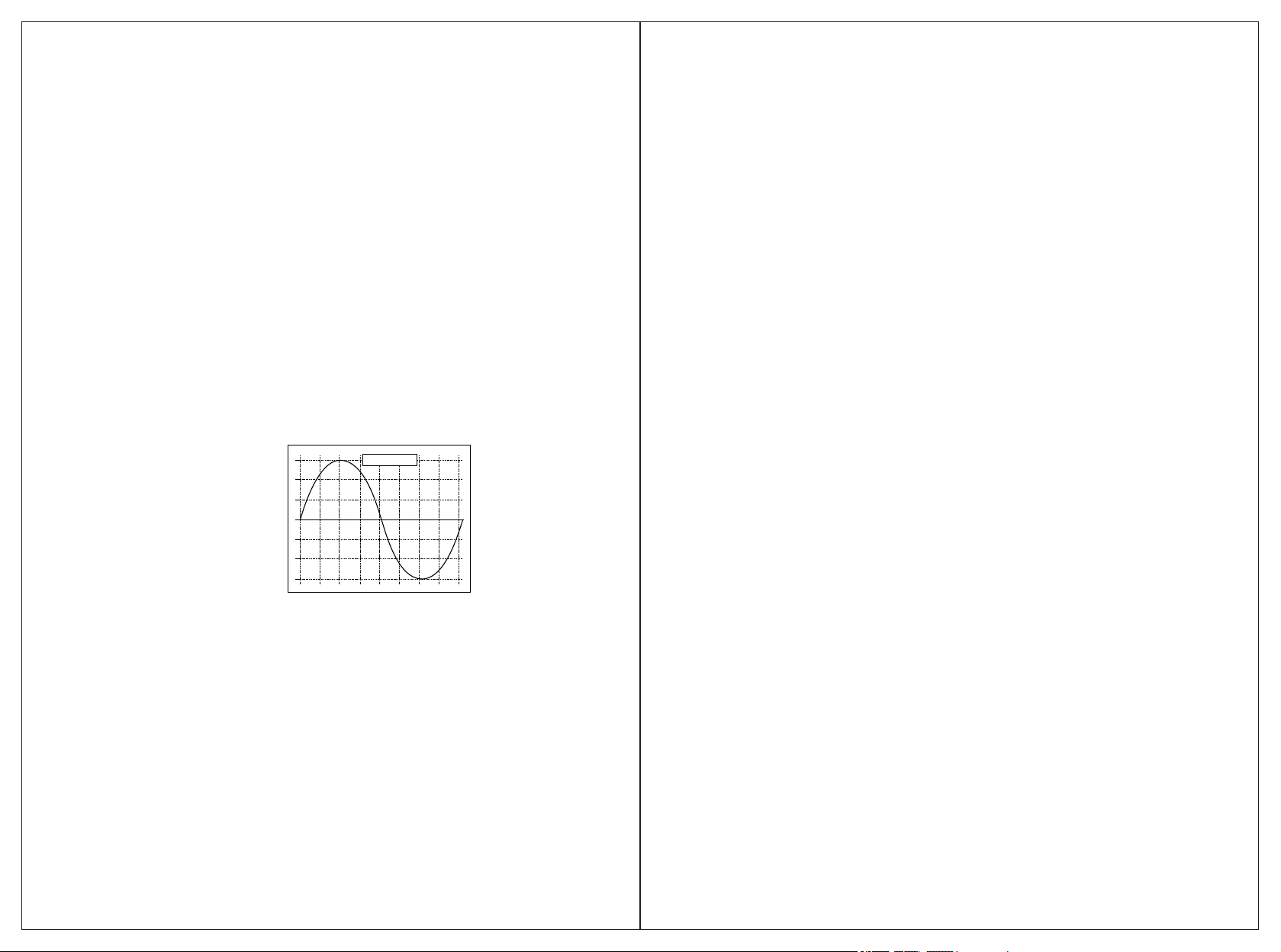
9. THE OUTPUT WAVE FORM
The output wave form of this inverter is Pure Sine Wave, which is much like the one
from utility-supplied AC electricity, even more purer; pure sine wave is applicable in
most of loads, including electrical equipments, such as Linear Adaptor, switching power
supply, transformer, and motor and so on.
Comparing with Modified wave form, for inductive loads such as refrigerator and electric
fans, pure sine wave form can improve its power factor and the battery's efficiency and
reduce working noises effectively from appliances. For capacitive loads such as adapter
of lap-top, pure sine wave can lower the rush current at work and reduce interferences to
increase reliability and prolong the life of the product.
Pure sine wave output
(240 VAC Model)
339 Volta peak
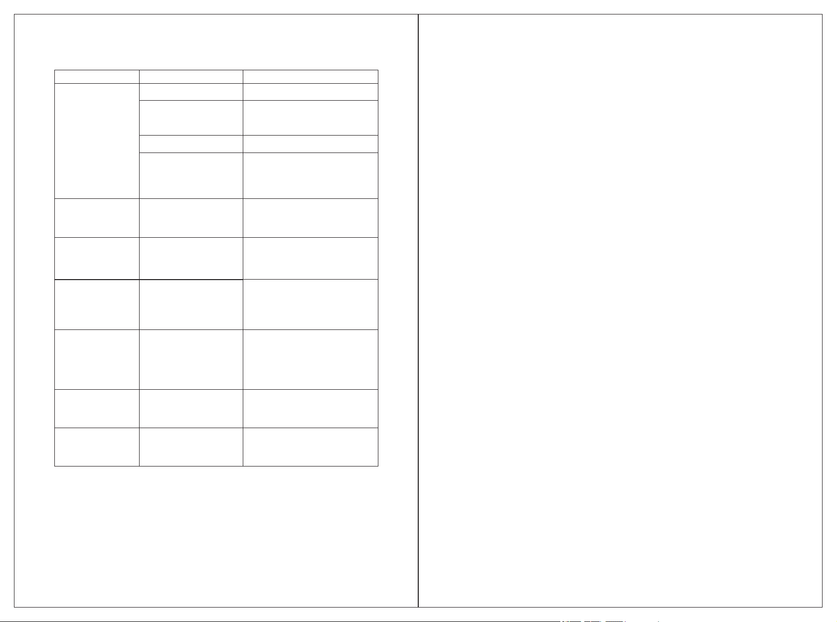
11. PROTECTION FUNCTION
1. Input under-voltage alarm: When the input DC voltage is lower than 9.8V
/19.6V/39.2V, the buzzer will whistle intermittently to remind that the inverter will go
into the under voltage protection. Pay attention to save the data if you are using
computer.
2. Under voltage protection: The inverter will automatically shut down when the
input DC voltage is lower than 9.5V/19V/38V. The buzzer will whistle continuously
and the digital display screen will show LO. Please turn off the inverter and use it
after recharging the battery.
3. Over voltage protection: The inverter will automatically shut down when the input
DC voltage is higher than 16V/32V/62V. The buzzer will whistle continuously and
the digital display screen will show HI. Please turn off the inverter and adjust the
input voltage to the admissible range.
4. Overload protection: The inverter will automatically shut down when the load
power is higher than the rated power. The buzzer will whistle continuously and the
digital display screen will show OL. Turn off the inverter and resume to normal
operation after taking away the redundant load.
5. Short-circuit protection: The AC output will be automatically shut down when
short circuit. And the digital display screen shows OL.
6. Thermal protection: The unit will be calorific during operation. If the temperature is
higher than 65℃, the inverter will automatically shut down. Then the buzzer will
whistle continuously and the digital display screen shows OH. Please turn off the
inverter, and continue using it after the temperature goes back to normal
temperature naturally. Meanwhile find out the factors causing the fault, such as
ventilation, ambient temperature, vent, load power and so on. It can avoid the
similar things happen again.
12. QUICK KNOWLEDGE ABOUT INVERTER
! Ensure Your Battery Size Is Big Enough And Voltage Is Correct.
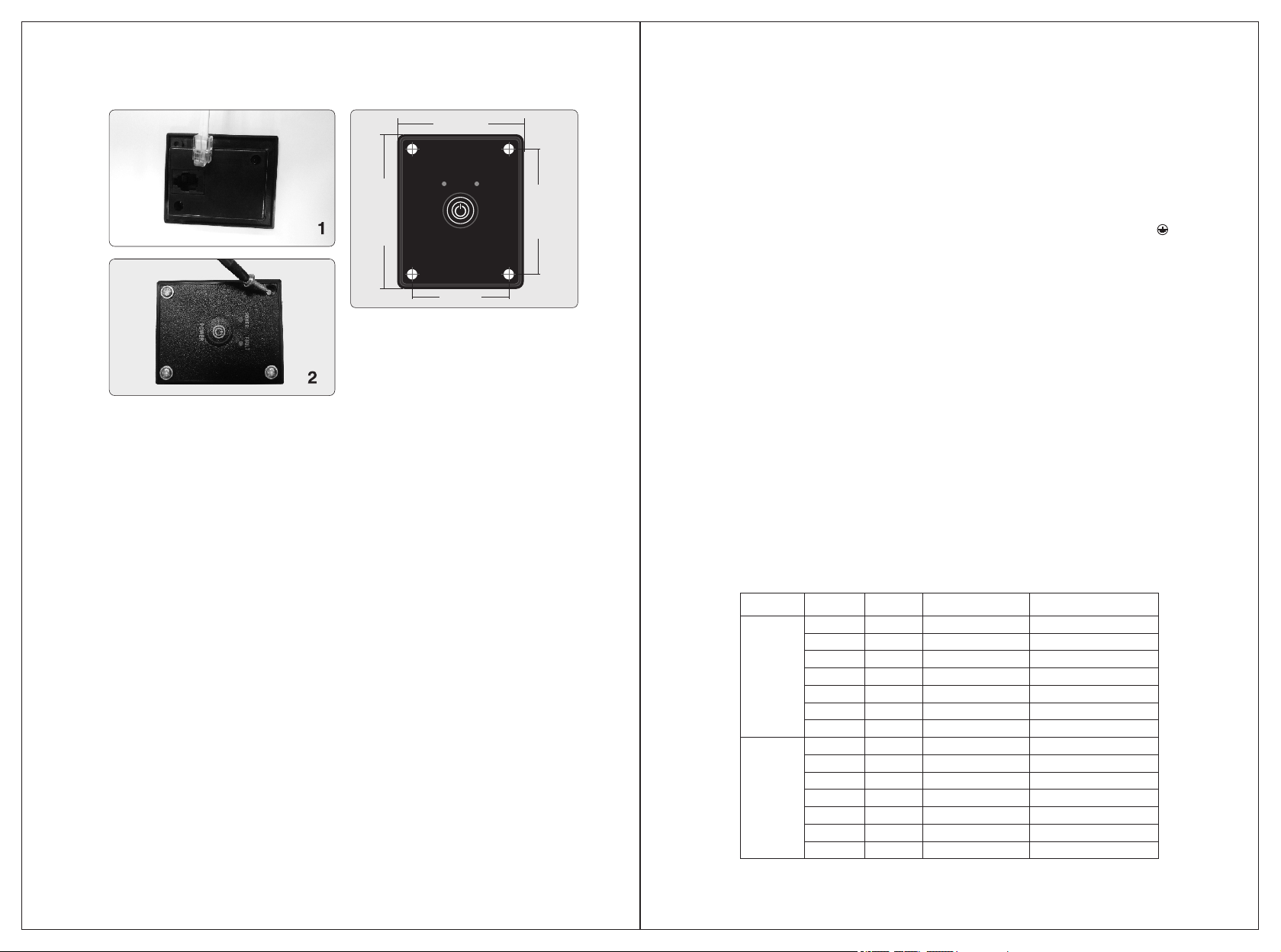
A. CORRECTLY CONNECTING THE INVERTER FOR FIRST USE.
1) Secure the provided Negative (black) DC cable connect to the Negative (-) bolt on
the inverter, and the other end to the Negative (-) post on the battery.
2) Secure the provided Positive (Red) DC cable to the Positive (+) bolt on the inverter,
and the other end to the Positive (+) post on the battery.
3) The nuts of the connection posts must be tightened to ensure well connected.
4) Press the power switch for one second, because it is a long press type switch.
WARNING: REVERSE CONNECTED THE CABLES WILL DAMAGE THE
INVERTER AND AVOID YOUR WARRANTY!
9.

10. 11.
13. WARRANTY
We take the guarantee of one year from the purchasing day. During the guarantee
period, any malfunction caused by our product quality, our company will fix or replace
the unit for free. But any one of the following conditions is beyond our guarantee terms.
1. The box distorted, damaged or changed, and interior parts damaged because of the
exterior hit or drop.
2. Connect the DC power adversely.
3. Dismantled or repaired the unit by un-granted person.
4. The unit was damaged by incorrect installation or operating method.
B. TROUBLESHOOTING TIPS
● Reduce the load power, or turn on the
appliance first, then turn on the inverter.
● Choose a bigger inverter
● Change a bigger battery and ensure fully
charged.
No output voltage,
buzzer whistles
continuously
Problem Reason Solutions
Low Input DC Voltage
High Input DC Voltage
Overload
Over temperature
● Check the rated voltage of the battery and
make sure that it is in the allowable range of
the input voltage.
● Do not use it when the battery is charging
Reduce the load power
● Restart it after it resumes to normal
temperature. Reduce the load. avoid
blocking the vent and improve the
ventilation condition.
● Cut off the load and let it cool naturally for
10 to 30 minutes.
No AC output voltage? 1.The power switch is off.
2.Poor contact with battery. ●Check the cables and make sure they are
tightly connected.
● Press the power switch for 1-2 second to
turn it on. it is a long press type switch
Output voltage below
100 V AC?
“True RMS”voltage meter is
required to properly measure
output voltage of modified
wave inverter
Cannot drive the load?
Tester indicated
"Open Ground"?
This is because it is not connected
to a"true Earth ground ", meaning it
is not connected to a metal rod
stuck in the Earth. it would be
impossible to do so in a boat or car
while moving. The power inverter
DOES NOT and cannot create a
true Earth ground on its own.
● Change the battery of the meter then test
again.
● Try to maintain the input voltage in the
range of rated power
● Test output voltage with a True RMS meter
3.Battery is too small.
2.The starting power is larger than
rated power (especially for
appliances with motor)
1.Load power is too large. Or the
actual power of the appliance
exceeds nominal power.
● Refer to the manual to do the Grounding
● Don't need the tester to do the Grounding
Test.
Starting alarm ?
instantaneous current is too large,
which leads to the detection of low
voltage and trigger under-voltage
alarm.
The main reason is that ths
Please restart the inverter several
times.
Got 40V or so while
testing inverter's
ground wire and
zero line?
This voltage has no meaning,
zero line can be ground.
This is normal, there is no current
leakage.
Low Input DC Voltage
If the unit still doesn't work normally after using all the methods above, it maybe
the internal faults of the circuit. Please contact seller for warranty.
Table of contents
Other Giandel Inverter manuals

Giandel
Giandel PM-1600KAR User manual

Giandel
Giandel PS-300C User manual

Giandel
Giandel PS-2200KAR User manual

Giandel
Giandel PURE SINE WAVE User manual

Giandel
Giandel PS-300B User manual

Giandel
Giandel PM-5000QBR User manual

Giandel
Giandel PS-3000QBR User manual

Giandel
Giandel PM-1100HB User manual

Giandel
Giandel PS-1200JCR User manual

Giandel
Giandel PM-300A User manual