cias IB-SERVER System manual


©CIAS Elettronica S.r.l. Ed 1.2
INDICE
1. DESCRIZIONE...............................................................................................................................................................3
1.1 DESCRIZIONE ...............................................................................................................................................................3
2. INSTALLAZIONE..........................................................................................................................................................4
2.1 INFORMAZIONI PRELIMINARI .......................................................................................................................................4
3. COLLEGAMENTI..........................................................................................................................................................5
3.1 MORSETTIERE,CONNETTORI E FUNZIONALITÀ DEL CIRCUITO .....................................................................................5
3.2 COLLEGAMENTO ALL’ALIMENTAZIONE PRINCIPALE ...................................................................................................7
3.3 CONNESSIONI LINEA SERIALE RS-485.........................................................................................................................8
4. APPLICAZIONI..............................................................................................................................................................9
4.1 APPLICAZIONI..............................................................................................................................................................9
4.2 MODALITÀ DI AUTOCONFIGURAZIONE ........................................................................................................................9
4.3 SINCRONISMO ORARIO...............................................................................................................................................10
4.4 CONTATTO DI TAMPER...............................................................................................................................................10
5. MANUTENZIONE E ASSISTENZA ..........................................................................................................................10
5.1 RICERCA GUASTI .......................................................................................................................................................10
Manuale d’installazione Pagina 1 di 18 IB-SERVER

©CIAS Elettronica S.r.l. Ed 1.2
INDEX
1. DESCRIPTION .............................................................................................................................................................11
1.1 DESCRIPTION .............................................................................................................................................................11
2. INSTALLATION...........................................................................................................................................................12
2.1 PRELIMINARY INFORMATION .....................................................................................................................................12
3. CONNECTIONS ...........................................................................................................................................................13
3.1 TERMINAL STRIPS,CONNECTORS AND CIRCUIT FUNCTION.........................................................................................13
3.2 CONNECTION TO MAIN POWER SUPPLY.......................................................................................................................15
3.3 RS-485 SERIAL LINE CONNECTION............................................................................................................................16
4. APPLICATIONS...........................................................................................................................................................17
4.1 APPLICATIONS ...........................................................................................................................................................17
4.2 AUTO-CONFIGURATION PROCEDURE ..........................................................................................................................17
4.3 HOUR SYNCHRO.........................................................................................................................................................18
4.3 TAMPER CONTACT.....................................................................................................................................................18
5. MAINTENANCE AND SERVICE ..............................................................................................................................18
5.1 FAULT LOCATION.......................................................................................................................................................18
Manuale d’installazione Pagina 2 di 18 IB-SERVER

©CIAS Elettronica S.r.l. Ed 1.2
1. DESCRIZIONE
1.1 Descrizione
IB-Server, è un server per il polling e la sincronizzazione oraria, in grado di segnalare mediante
protocollo universale on/off gli stati di: Allarme, Manomissione, Guasto e Nessuna Risposta,
comunicati su una linea seriale RS-485 (con protocollo Cias C - ONE BUS Versione 7 o
successivo) dai rivelatori digitali quali Barriere, rivelatori singoli, espansioni di campo per
rivelatori tradizionali (Trasponder 1/8)ad esso connessi.
È possibile connettere sino ad un numero massimo si 88 rivelatori mentre non vi è alcuna
limitazione di IB-Island collegabili (solo il limite fisico imposto dalla linea seriale RS-485).
Per ogni tipologia di dispositiv, è possibile connettere al massimo:
•11 IB-Trasponder, i quali raggruppano 8 sensori tradizionali
•44 Barriere (Rx e Tx)
•88 Sensori monoteista (IB-Trasponder1, Armidor, Il solo Ricevitore della barriera)
oppure è possibile connettere contemporaneamente le diverse tipologie purchè non si superi il
numero massimo di 88.
Sistema di Interconnessione – IB-System
Manuale d’installazione Pagina 3 di 18 IB-SERVER

©CIAS Elettronica S.r.l. Ed 1.2
2. INSTALLAZIONE
2.1 Informazioni Preliminari
Nella figura sottoriportata è rappresentata la configurazione hardware di IB-Server.
FUSE F6 FOR J24
AUXILIARY OUT
VOLTAGE (2A)
FUSE F2 FOR J8
BATTERY
INPUT (2 A)
LED
MAIN
POWER
OK
GND
+13,8
GND
+13,8
GND
+13,8
A.R.
NC
COM
NO
GND
+13,8
GND
IN 0
IN 4
IN 1
IN 5
IN 2
IN 6
IN 3
IN 7
GND
GND
+13,8
GND
+13,8
-LL -LL
+LH +LH
TAMPER
INPUT
FUSE F4 FOR J16 -J17
AUXILIARY OUT
VOLTAGE (2 A)
FUSE F3 FOR J15
AUXILIARY OUT
VOLTAGE (2 A)
TERMINAL
U4
U0
JP3
RS-485
TASTIERE
RS-485
FIELD
uP
RESET
CLOCK BATTERY
B/U ON
JP1
JP2
JP4
CLOCK BATTERY
B/U
JP5
U5
U1
U6
U2
U7
U3
GND
KEY1
KEY2
KEY3
KEY4
BAK
BUZ
LED1
LED2
LED3
LED4
CK
VM
SD
GND
CLB
RDB
FIELD
NC COM NO
OUT4 NC COM NO
OUT3 NC COM NO
OUT2 NO COM NC
OUT1
FIELD LINE
TERMINATION
TERMINAL LINE
TERMINATION
PARALEL PRINTER
FUSE F5 FOR J23
AUXILIARY OUT
VOLTAGE (2 A)
J1J4
J3J2J12
J23J11J15
J7
J24
J5
J13
J6 J21
J22
J8
J10
J17
J16
J19
400 mm
350 mm 57mm 22mm
520 mm
480mm
MS 2 MS 3 MS 4
LINEA 4
3
2
1
3
2
1
3
2
1
3
2
1
LINEA 3
LINEA 2
LINEA 1
LH LO
Tx4
Tx3
Tx2
Tx1
S1
Jp1
Jp3
Jp2
Jp4
BUSREP
13.8 Vdc 3 A
SWITCHING
POWER SUPPLY
AND BATTERY
CHARGER
LOLHGND
+13,8
LH LOLHLO
Space For Battery
MAX 12 V 18Ah
IB-Server è composto da:
- 4 IB-Island - Moduli di trasformazione del segnale RS-485 in segnale
on/off;
- 1 BUS-REP - Ripetitore / moltiplicatore di linea seriale RS-485 a 3
uscite;
- Scheda Madre - Unità centrale di gestione;
- Alimentatore - Unità alimentatore;
Manuale d’installazione Pagina 4 di 18 IB-SERVER

©CIAS Elettronica S.r.l. Ed 1.2
3. COLLEGAMENTI
3.1 Morsettiere, Connettori e Funzionalità del circuito
Di seguito sono rappresentate le connessioni a IB-Server.
FUSE F6 FOR J24
AUXILIARY OUT
VOLTA GE ( 2 A)
FUSE F2 FOR J8
BATTERY
INPUT (2 A)
LED
MAIN
POWER
OK
GND
+13,8
GND
+13,8
GND
+13,8
A.R.
NC
COM
NO
GND
+13,8
GND
IN 0
IN 4
IN 1
IN 5
IN 2
IN 6
IN 3
IN 7
GND
GND
+13 ,8
GND
+13, 8
-LL -LL
+LH +LH
TAMP ER
INPUT
FUSE F4 FOR J16-J17
AUXI LIAR Y OUT
VOLTAGE(2A)
FUSE F3 FOR J15
AUXILIARY OUT
VOLTA GE ( 2 A)
TERMINAL
U4
U0
JP3
RS-485
TASTIE RE
RS-485
FIELD
uP
RESET
CLOCK BATTERY
B/U ON
JP1
JP2
JP4
CLOCK BATTERY
B/U
JP5
U5
U1
U6
U2
U7
U3
GND
KEY1
KEY2
KEY3
KEY4
BAK
BUZ
LED1
LED2
LED3
LED4
CK
VM
SD
GND
CLB
RDB
FIELD
NC COM NO
OUT4 NCC OM NO
OUT3 NCC OM NO
OUT2 NO COM NC
OUT1
FIELD LINE
TERMINATION
TERMINAL LINE
TERMINATION
PARALELPRINTER
FUSE F5 FOR J23
AUXILIARY OUT
VOLTA GE ( 2 A)
J1J4
J3J2J12
J23J11J15
J7
J24
J5
J13
J6 J21
J22
J8
J10
J17
J16
J19
Alloggiamento
per batteria da
MAX 12 V 18Ah
MS 2 MS 3 MS 4
LINEA 4
3
2
1
3
2
1
3
2
1
3
2
1
LINEA 3
LINEA 2
LINEA 1
LH LO
Tx4
Tx3
Tx2
Tx1
S1
Jp1
Jp3
Jp2
Jp4
BUSREP
13.8 Vdc 3 A
SWITCHING
POWER SUPPLY
AND BATTERY
CHARGER
LOLHGND
+13,8
LHLOLHLO
MS 2 MS 3 MS 4
LINEA 4
3
2
1
LINEA 3
LINEA 2
LH LO
Tx4
Tx3
Tx2
Tx1
Jp3
BUSREP
LH LOLH LO
NC
COM
NO NC
COM
NO NC
COM
NO NC
COM
NO
MS3
L
N
1
1
111
MORSETTIERA MS3 IB-ISLAND
Morsettiera Uscita Relè di stato dei moduli IB-ISLAND
Mors. Simbolo FUNZIONE TIPO DI USCITA
1 NO Contatto Normalmente Aperto
2 COM Comune
3 NC Contatto Normalmente Chiuso(*)
RELE’ DI ALLARME (RL1)
4 NO Contatto Normalmente Aperto
5 COM Comune
6 NC Contatto Normalmente Chiuso(*)
RELE’ DI MANOMISSIONE (RL2)
7 NO Contatto Normalmente Aperto
8 COM Comune
9 NC Contatto Normalmente Chiuso(*)
RELE’ DI GUASTO (RL3)
10 NO Contatto Normalmente Aperto
11 COM Comune
12 NC Contatto Normalmente Chiuso(*)
RELE’ DI NESSUNA RISPOSTA
(RL4)
(*) Condizione di Default con relè eccitato
Manuale d’installazione Pagina 5 di 18 IB-SERVER

©CIAS Elettronica S.r.l. Ed 1.2
MORSETTIERA MS2 BUS-REP
Uscita Linea Seriale RS-485
Mors. Simbolo FUNZIONE
1 LH Linea Seriale (Linea Alta)
2 LO Linea Seriale (Linea Bassa)
3 GND - Massa Linea Seriale
4 Connessione Schermo
MORSETTIERA MS3 BUS-REP
Uscita Linea Seriale RS-485
Mors. Simbolo FUNZIONE
1 LH Linea Seriale (Linea Alta)
2 LO Linea Seriale (Linea Bassa)
3 GND - Massa Linea Seriale
4 Connessione Schermo
MORSETTIERA MS4 BUS-REP
Uscita Linea Seriale RS-485
Mors. Simbolo FUNZIONE
1 LH Linea Seriale (Linea Alta)
2 LO Linea Seriale (Linea Bassa)
3 GND - Massa Linea Seriale
4 Connessione Schermo
MORSETTIERA AC IN Alimentatore
Ingresso Alimentazione 230 V∼
Mors. Simbolo FUNZIONE
1 L Ingresso Fase 230 V∼
2 Non Utiliz. Non Utilizzato
3 N Ingresso Neutro 230 V∼
4 Non Utiliz. Non Utilizzato
5 Terra
Manuale d’installazione Pagina 6 di 18 IB-SERVER

©CIAS Elettronica S.r.l. Ed 1.2
3.2 Collegamento all’Alimentazione Principale
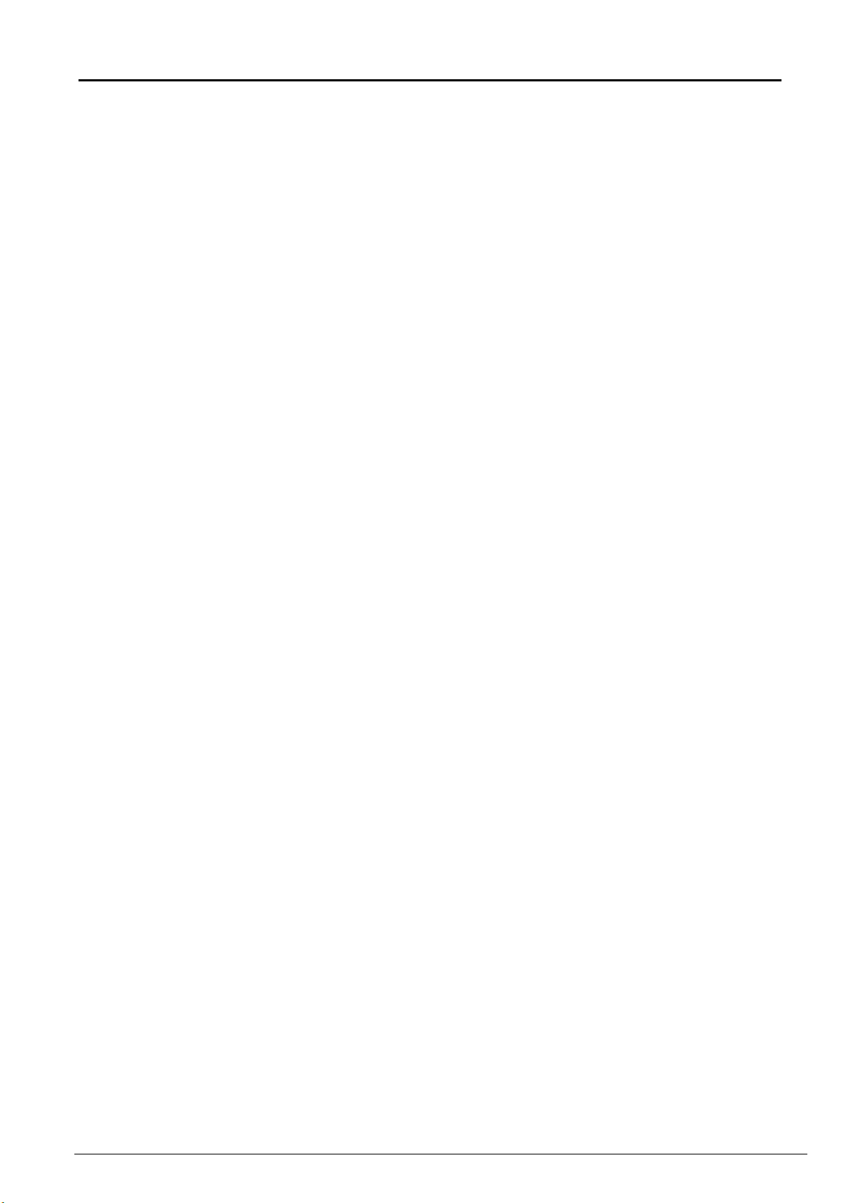
IB-Server dispone di un Alimentatore, connesso alla Rete di alimentazione a 230 V∼, mediante il
quale viene alimentato tutto l’insieme IB-Server (Scheda Madre, IB-Island, Bus-Rep).
Per una corretta installazione di IB-Server occorre seguire le indicazioni di seguito riportate.
Occorre in ogni caso attenersi, scrupolosamente, alle prescrizioni contenute nella
normativa CEI 64-8 e 46-90 in materia di installazioni fisse di apparati collegati
permanentemente alla rete di alimentazione. Tutti i conduttori attestati alle morsettiere non
debbono essere consolidati con saldatura dolce nel punto di attestazione, inoltre, al fine di
evitare contatti accidentali tra conduttori, a bassissima tensione funzionale, ed altri conduttori a
tensioni pericolose, è necessario che essi siano ancorati in prossimità delle attestazioni,
mediante fascette fissate al fondo del contenitore. Lo schermo di tutti i cavi delle periferiche,
deve essere collegato al circuito di terra della centrale.
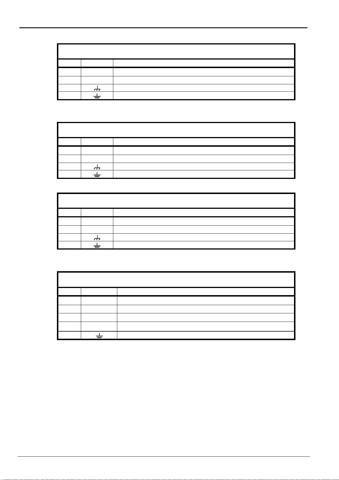
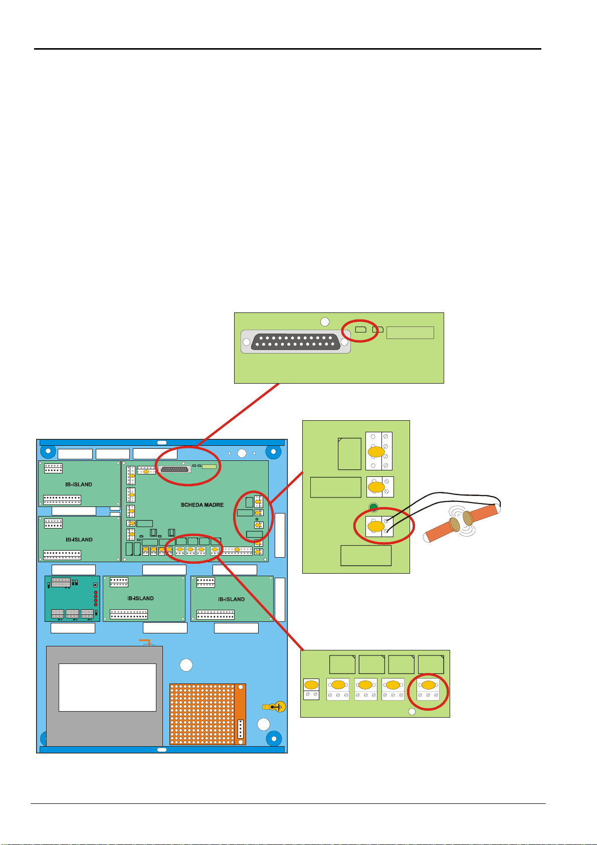
IB-Server, deve essere alimentato con una tensione primaria di 230V∼/50 Hz; allo scopo
collegare i conduttori di rete ai morsetti 0÷230 dell’alimentatore switching, collegare quindi il
conduttore di terra all’apposito morsetto dell’alimentatore. La tensione 230V∼deve essere
fornita a IB-Server tramite un idoneo dispositivo di sezionamento che abbia le seguenti
caratteristiche:
•Bipolare con una distanza minima tra i contatti di 3 mm
•Previsto nell’impianto fisso
•Facilmente accessibile
I conduttori di alimentazione 230 V∼ed il conduttore di terra, debbono essere introdotti nel
IB-Server, esclusivamente attraverso l’apposito foro, e fissati al IB-Server mediante la
fascetta in dotazione. Inoltre gli involucri delle batterie tampone utilizzate, debbono avere
una classe di autoestinguenza HB o migliore;
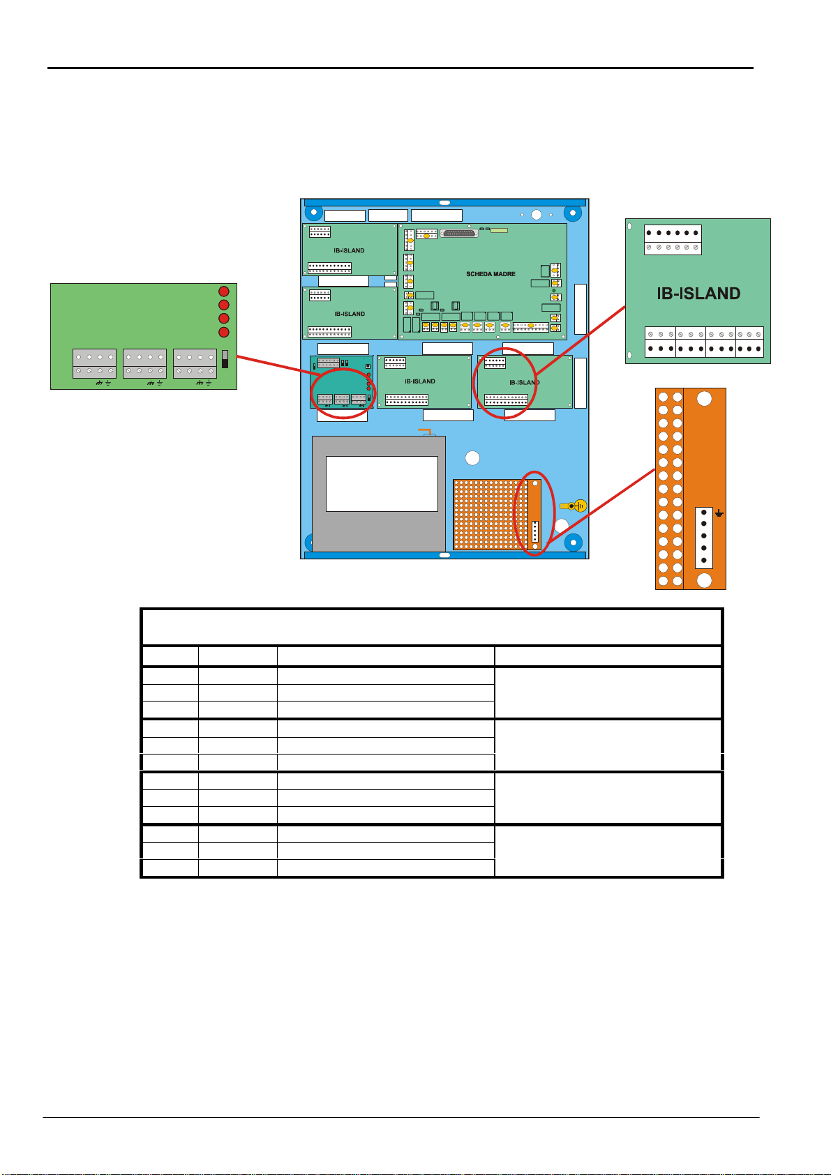
Connettere il cavo di alimentazione proveniente dalla rete ai morsetti 1 Fase, 3 Neutro, 5 Terra,
seguendo la tabella a pagina 6 “Morsettiera AC IN Alimentatore”
Manuale d’installazione Pagina 7 di 18 IB-SERVER

©CIAS Elettronica S.r.l. Ed 1.2
3.3 Connessioni Linea Seriale RS-485
IB-Server è composto da :
una Scheda Madre : Gestisce il polling sulla linea seriale;
quattro IB-Island : Trasmettono l’informazione dei Rivelatori collegati in linea seriale,
tramite Relè;
un Bus-Rep : Moltiplica e disaccoppia la linea seriale di ingesso proveniente dalla
Scheda Madre in 3 linee seriali di uscita per i Rivelatori ed IB-Island.
Per il funzionamento di IB-Server è necessario effettuare tutti i collegamenti in modo corretto,
connettendo i Rivelatori su una o più line seriali provenienti dal Bus-Rep (MS2, MS3 MS4).
Inoltre è indispensabile che i Rivelatori collegati alla linea seriale abbiano un indirizzo univoco e
allo stesso modo i dispositivi IB-Island siano impostati con lo stesso indirizzo riferito al rivelatore
da controllare (per le connessioni riferirsi al capitolo 3.1 tabella Bus-Rep). Per gli indirizzi di ogni
dispositivo riferirsi al relativo manuale.
Per il tipo di cavo da utilizzare e tutte le altre considerazioni riguardanti la linea seriale, riferirsi al
manuale BUS-REP.
FUSE F6 FOR J24
AUXILIARYOUT
VOLTAGE (2A)
FUSE F2 FOR J8
BATTERY
INPUT (2 A)
LED
MAIN
POWER
OK
GND
+13,8
GND
+13,8
GND
+13,8
A.R.
NC
COM
NO
GND
+13,8
GND
IN 0
IN 4
IN 1
IN 5
IN 2
IN 6
IN 3
IN 7
GND
GND
+13 ,8
GND
+13,8
-LL -LL
+LH +LH
TAMPER
INPUT
FUSE F4 FOR J 16-J1 7
AUXILI ARY OUT
VOLTAGE(2 A)
FUSE F3 FOR J15
AUXILIARYOUT
VO LTA GE ( 2 A)
TERMINAL
U4
U0
JP3
RS-485
TAS TIE RE
RS-485
FIELD
uP
RESET
CLOCK BATTERY
B/U ON
JP1
JP2
JP4
CLOC K BATTERY
B/U
JP5
U5
U1
U6
U2
U7
U3
GND
KEY1
KEY2
KEY3
KEY4
BAK
BUZ
LED1
LED2
LED3
LED4
CK
VM
SD
GND
CLB
RDB
FIELD
NC COM NO
OUT4 NC COM NO
OUT3 NC COM NO
OUT2 NO COM NC
OUT1
FIELD LINE
TER MINATION
TERMINAL LINE
TERMINATION
PARALEL PRINTER
FUSE F5 FOR J23
AUXILIARYOUT
VOLTAGE (2A)
J1J4
J3J2J12J23J11J15
J7
J24
J5
J13
J6 J21
J22
J8
J10
J17
J16
J19
Alloggiamento
per batteria da
MAX 12 V 18 Ah
MS 2 MS 3 MS 4
LINEA 4
3
2
1
3
2
1
3
2
1
3
2
1
LINEA 3
LINEA 2
LINEA 1
LHLO
Tx4
Tx3
Tx2
Tx1
S1
Jp1
Jp3
Jp2
Jp4
BUSREP
13.8 Vdc 3 A
SWITCHING
POWER SUPPLY
AND BATTERY
CHARGER
LOLHGND
+13,8
LH LOLH LO
MS 2 MS 3 MS 4
LINEA 4
3
2
1
LINEA 3
LINEA 2
LH LO
Tx4
Tx3
Tx2
Tx1
Jp3
BUSREP
LH LOLH LO
111
Rivelatore
Rivelatore
IB-Island
Barriera
Barriera
IB-Trasponder
Manuale d’installazione Pagina 8 di 18 IB-SERVER

©CIAS Elettronica S.r.l. Ed 1.2
4. APPLICAZIONI
4.1 Applicazioni
IB-Server viene utilizzato per effettuare il polling e mantenere il sincronismo orario, dei sensori ad
esso connessi tramite una linea seriale RS-485. È possibile rilevare automaticamente la
configurazione del campo tramite la funzione di autoconfigurazione.
4.2 Modalità di Autoconfigurazione
Per effettuare l’autoconfigurazione, smontare il coperchio del IB-Server svitando le apposite viti in
modo da generare l’apertura del Tamper.
Chiudere per qualche secondo, il ponticello di “Reset” (Jp4) sulla “Scheda Madre”. Richiudere il
coperchio. IB-Server eseguirà la ricerca sul campo collegato, al termine della quale inizierà il
polling ai Rivelatori presenti.
FUSE F6 FOR J24
AUXILIARYOUT
VOLTAGE (2 A)
FUSE F2 FOR J8
BATTERY
INPUT (2 A)
LED
MAIN
POWER
OK
GND
+13,8
GND
+13,8
GND
+13,8
A.R.
NC
COM
NO
GND
+13,8
GND
IN 0
IN 4
IN 1
IN 5
IN 2
IN 6
IN 3
IN 7
GND
GND
+13,8
GND
+13,8
-LL -LL
+LH +LH
TAM PER
INPUT
FUSE F4 FOR J1 6-J17
AUXI LIARY O UT
VOLTAGE(2 A)
FUSE F3 FO R J15
AUXILIARY OUT
VOLTAGE (2A)
TERMINAL
U4
U0
JP3
RS-485
TASTIER E
RS-485
FIELD
uP
RESET
CLOCK BATTERY
B/U ON
JP1
JP2
JP4
CLOCK BATTERY
B/U
JP5
U5
U1
U6
U2
U7
U3
GND
KEY1
KEY2
KEY3
KEY4
BAK
BUZ
LED1
LED2
LED3
LED4
CK
VM
SD
GND
CLB
RDB
FIELD
NC COM NO
OUT4 NC COM NO
OUT3 NCC OM NO
OUT2 NO COM NC
OUT1
FIELD LINE
TERMINATION
TERMINAL LINE
TERMINATION
PARA LEL PRINTER
FUSE F5 FOR J23
AUXILIARYOUT
VOLTA GE (2 A)
J1J4J3
J2J12J23J11J15
J7
J24
J5
J13
J6 J21
J22
J8
J10
J17
J16
J19
Alloggiamento
per batteria da
MAX 12 V 18Ah
MS 2 MS 3 MS 4
LINEA 4
3
2
1
3
2
1
3
2
1
3
2
1
LINEA 3
LINEA 2
LINEA 1
LH LO
Tx4
Tx3
Tx2
Tx1
S1
Jp1
Jp3
Jp2
Jp4
BUSREP
13.8 Vdc 3 A
SWITCHING
POWER SUPPLY
AND BATTERY
CHARGER
LOLHGND
+13,8
LHLOLHLO
RESET
JP2
JP4
CLOCK BATTERY
B/U
PARALEL PRINTER
FUSE F2 FOR J8
BATTERY
INPUT (2 A)
LED
MAIN
POWER
OK
GND
+13,8
A.R.
NC
COM
NO
TAMPER
INPUT
FUSE F4 FOR J16-J17
AUXILIARY OUT
VOLTAGE (2 A)
J22
J8
J10
-LL +LH
FIELD
NC COM NO
OUT4 NC COM NO
OUT3 NC COM NO
OUT2 NO COM NC
OUT1
J1J4
J3
J2J12
MAGNETE DA FISSARE
SULLA PARETE DIETRO
IL FONDO
DEL CONTENITORE
CONTATTO REED
DA FISSARE
SUL COPERCHIO
DEL CONTENITORE
Manuale d’installazione Pagina 9 di 18 IB-SERVER

©CIAS Elettronica S.r.l. Ed 1.2
4.3 Sincronismo Orario
Il sincronismo degli orologi di tutti i rivelatori avviene automaticamente ogni mezzanotte o ad ogni
modifica della data / ora di uno qualunque dei rivelatori.
4.4 Contatto di Tamper
Ai morsetti “TAMPER” della morsettiera (J10) vanno collegati i due conduttori provenienti dal
contatto normalmente chiuso, di tipo “reed”, che protegge la centrale dall’apertura del contenitore
metallico.
L’apertura di questo contatto produce l’attivazione del relè di manomissione (OUT 1) presente
sulla scheda (figura pagina 9).
5. MANUTENZIONE E ASSISTENZA
5.1 Ricerca Guasti
Guasto
Possibile Causa
Possibile Soluzione
Connessioni errate tra IB-Island e
Rivelatore Verificare le connessioni
Impostazione indirizzo IB-Island
Errato Verificare l’indirizzo impostato
sugli IB-Island e del relativo
Rivelatore
IB-Server Non configurato Eseguire la procedura di
Autoconfigurazione
Gli IB-Island non rilevano
nessuno stato
Guasto IB-Server Sostituire IB-Server
Connessione IB-Island Errata Verificare le connessioniUn IB-Island non rivela nessuno
stato Impostazione indirizzo IB-Island
Errato Verificare l’indirizzo impostato
sugli IB-Island
Connessione a Rivelatore errata Verificare le connessioniIB-Island rivela solo lo stato di
Nessuna Risposta Impostazione Indirizzo
Rivelatore/IB-Island errata Verificare che l’indirizzo
del IB-Island sia lo stesso del
Rivelatore
Manuale d’installazione Pagina 10 di 18 IB-SERVER

©CIAS Elettronica S.r.l. Ed 1.2
1. DESCRIPTION
1.1 Description
The IB-Server unit is a polling server with the capability to show with on/off universal protocol the
following alarms state: alarm, tampering, failure and line failure.
It operates by means of a RS-485 serial line with digital units connected to it (CIAS protocol C -
ONE BUS version 7 or subsequent).
It’s possible to connect till 88 devices. No limitation on the number of IB Island (only the physical
limit of the RS 485).
For each kind of device it is possible to connect on the serial bus a max
•11 IB-Trasponder 8 (each one corresponds 8 traditional detectors)
•44 Barrier (Receiver and Transmitter)
•88 Single devices (IB-Transponder 1, Armidor, only Rx barrier)
Or a mix of Them.
IB-System: Interconnection system
Installation Handbook Page 11 of 18 IB-SERVER

©CIAS Elettronica S.r.l. Ed 1.2
2. INSTALLATION
2.1 Preliminary information
The figure shown below represent the IB-Server hardware configuration.
FUSE F6 FOR J 24
AUXILIARY OUT
VOLTAGE (2 A)
FUSE F2 FOR J 8
BATTERY
INPUT (2 A)
LED
MAIN
POWER
OK
GND
+13,8
GND
+13,8
GND
+13,8
A.R.
NC
COM
NO
GND
+13,8
GND
IN 0
IN 4
IN 1
IN 5
IN 2
IN 6
IN 3
IN 7
GND
GND
+13,8
GND
+13,8
-LL -LL
+LH +LH
TAMPER
INPUT
FUSE F4 FOR J16-J17
AUXILIARY OUT
VOLTAGE (2 A )
FUSE F3 FOR J 15
AUXILIARY OUT
VOLTAGE (2 A)
TERMINAL
U4
U0
JP3
RS-485
TASTIERE
RS-485
FIELD
uP
RESET
CLOCK BATTERY
B/U ON
JP1
JP2
JP4
CLOCK BATTERY
B/U
JP5
U5
U1
U6
U2
U7
U3
GND
KEY1
KEY2
KEY3
KEY4
BAK
BUZ
LED1
LED2
LED3
LED4
CK
VM
SD
GND
CLB
RDB
FIELD
NC COM NO
OUT4 NC COM NO
OUT3 NC COM NO
OUT2 NO COM NC
OUT1
FIELD LINE
TERMINATION
TERMINAL LINE
TERMINATION
PARALEL PRINTER
FUSE F5 FOR J 23
AUXILIARY OUT
VOLTAGE (2 A)
J1J4
J3J2J12
J23J11J15
J7
J24
J5
J13
J6 J21
J22
J8
J10
J17
J16
J19
400 mm
350 mm 57mm 22mm
520 mm
480mm
MS 2 MS 3 MS 4
LINEA 4
3
2
1
3
2
1
3
2
1
3
2
1
LINEA3
LINEA 2
LINEA1
LH LO
Tx4
Tx3
Tx2
Tx1
S1
Jp1
Jp3
Jp2
Jp4
BUSREP
13.8 Vdc 3 A
SWITCHING
POWER SUPPLY
AND BATTERY
CHARGER
LOLHGND
+13,8
LH LOLH LO
Space For Battery
MAX 12 V 18Ah
IB-Server composition:
- 4 IB-Island - Module for RS-485 signal translation to on/off signal;
- 1 BUS-REP - Serial line RS-485 Repeater / Multiplier with 3 output;
- Mother-board IB-Server - Management central unit.
- Power supply Power supply unit
Installation Handbook Page 12 of 18 IB-SERVER

©CIAS Elettronica S.r.l. Ed 1.2
3. CONNECTIONS
3.1 Terminal strips, Connectors and circuit function
Below is shown the connection scheme of IB Server.
FUSE F 6 FOR J24
AUXILIARY OUT
VOLTAGE (2 A)
FUSE F2 FOR J8
BATTERY
INPUT (2 A)
LED
MAIN
POWER
OK
GND
+13,8
GND
+13,8
GND
+13,8
A.R.
NC
COM
NO
GND
+13,8
GND
IN 0
IN 4
IN 1
IN 5
IN 2
IN 6
IN 3
IN 7
GND
GND
+13 ,8
GND
+13, 8
-LL -LL
+LH +LH
TAMP ER
INPUT
FUSE F4 FOR J16-J17
AUXI LIAR Y OUT
VOLTAGE(2 A)
FUSE F3 FOR J15
AUXILIARY OUT
VOLTA GE ( 2 A)
TERMINAL
U4
U0
JP3
RS-485
TASTIE RE
RS-485
FIELD
uP
RESET
CLOCK BATTERY
B/U ON
JP1
JP2
JP4
CLOCK BATTERY
B/U
JP5
U5
U1
U6
U2
U7
U3
GND
KEY1
KEY2
KEY3
KEY4
BAK
BUZ
LED1
LED2
LED3
LED4
CK
VM
SD
GND
CLB
RDB
FIELD
NC COM NO
OUT4 NCC OM NO
OUT3 NCC OM NO
OUT2 NO COM NC
OUT1
FIELD LINE
TERMINATION
TERMINAL LINE
TERMINATION
PARA LEL PRINT ER
FUSE F5 FOR J23
AUXILIARY OUT
VOLTA GE ( 2 A)
J1J4
J3J2J12
J23J11J15
J7
J24
J5
J13
J6 J21
J22
J8
J10
J17
J16
J19
Space For Battery
MAX 12 V 18 Ah
MS 2 MS 3 MS 4
LINEA 4
3
2
1
3
2
1
3
2
1
3
2
1
LINEA 3
LINEA 2
LINEA 1
LH LO
Tx4
Tx3
Tx2
Tx1
S1
Jp1
Jp3
Jp2
Jp4
BUSREP
13.8 Vdc 3 A
SWITCHING
POWER SUPPLY
AND BATTERY
CHARGER
LOLHGND
+13,8
LHLOLHLO
MS 2 MS 3 MS 4
LINEA 4
3
2
1
LINEA 3
LINEA 2
LH LO
Tx4
Tx3
Tx2
Tx1
Jp3
BUSREP
LH LOLH LO
NC
COM
NO NC
COM
NO NC
COM
NO NC
COM
NO
MS3
L
N
1
1
111
TERMINAL BLOCK MS3 IB-ISLAND
Output terminal strip, status relais of IB-ISLAND modules
Pin Symbol FUNCTION OUTPUT KIND
1 NO Normal open contact
2 COM Common
3 NC Normal close contact(*)
ALARM RELAY (RL1)
4 NO Normal open contact
5 COM Common
6 NC Normal close contact(*)
TAMPER RELAY (RL2)
7 NO Normal open contact
8 COM Common
9 NC Normal close contact(*)
FAILURE RELAY (RL3)
10 NO Normal open contact
11 COM Common
12 NC Normal close contact(*)
NO ANSWER RELAY (RL4)
(*) Default Conditions with active relay
Installation Handbook Page 13 of 18 IB-SERVER

©CIAS Elettronica S.r.l. Ed 1.2
TERMINAL BLOCK MS2 BUS-REP
RS-485 Serial Line Output
Pin Symbol FUNCTION
1 LH Serial Line (High)
2 LO Serial Line (Low)
3 GND - Serial Line Ground
4 Shield Connection
TERMINAL BLOCK MS3 BUS-REP
RS-485 Serial Line Output
Pin Symbol FUNCTION
1 LH Serial Line (High)
2 LO Serial Line (Low)
3 GND - Serial Line Ground
4 Shield Connection
TERMINAL BLOCK MS4 BUS-REP
RS-485 Serial Line Output
Pin Symbol FUNCTION
1 LH Serial Line (High)
2 LO Serial Line (Low)
3 GND - Serial Line Ground
4 Shield Connection
TERMINAL BLOCK AC IN Power supply
Power supply Input 230 V∼
Pin Symbol FUNCTION
1 L Phase conductor input 230 V∼
2 Not Used Not Used
3 N Neutral conductor input 230 V∼
4 Not Used Not Used
5 Ground
Installation Handbook Page 14 of 18 IB-SERVER

©CIAS Elettronica S.r.l. Ed 1.2
3.2 Connection to main power supply
IB Server has a Power supply connected to the 230 V∼, which supply the all IB Server components
(Mother Board, IB Islands, Bus rep).
For a correct installation of IB Server follow the next indications: Anyway it’s necessary to follow
in details the rules of the CEI 64-8 and 46-90 about the fixed installation of devices
permanently connected to high voltage power supply. All the conductors connected to the
terminal blocks must be connected without soldering in the connection point, furthermore to
avoid accidental contact between the conductors, at very low functional voltage, and other
conductors with dangerous voltages, it’s necessary that they will be fixed at the connection point
side with wraps fixed to the housing. The shield of all the cables of the peripherical must be
connected to the earth of the control panel.
IB Server must per supplied with a primary voltage of 230 V∼/50Hz; with the pur pose to connect
the main conductors to the 0÷230 terminal blocks of the switching power supply, connect the earth
conductor to the right power supply terminal block. The voltage 230V∼must be supplied to IB
Server through a suitable dissection device which has the following features:
•Bipolar with a distance minimum of 3 mm
•Foreseen on the general fixed system
•Easy accessible
The conductors of the 230V∼and the earth conductor, must be introduced into IB Server
only through the proper hole, and fixed to Ib Server through the wraps included.
Furthermore the battery housings, must have a fire resistant class HB or better;
Connect the Power supply cable coming from the main to the terminal blocks 1 Phase, 3 Neutral, 5
Earth, following the table at page 6 “TERMINAL BLOCK AC IN Power supply
Installation Handbook Page 15 of 18 IB-SERVER

©CIAS Elettronica S.r.l. Ed 1.2
3.3 RS-485 Serial Line Connection
IB-Server is made of:
One Mother Board: It manages the polling of the Bus line
Four IB Islands: which translate the serial information into on/off signals with relays
One Bus Rep: It pump up and decuple the serial line coming from the mother board
dividing it into 3 lines for detectors and IB Islands
For the functioning of IB Server is necessary to do all the connection in the right way, connecting
the detectors to one or more serial lines coming from the Bus Rep (MS2, MS3, MS4).
Furthermore is obligatory that the detectors connected to the serial line have a unique address and
at the same time the IB Island must have the same address of the detector to control (refer to
chapter 3.1 table Bus Rep). To address each device refer to the specific manual. For the cable to
use and other consideration on the serial line refer to the BUS-REP manual.
FUSEF6 FOR J24
AUXILIARYOUT
VOLTAGE (2 A)
FUSE F2 FOR J8
BATTERY
INPUT (2 A)
LED
MAIN
POWER
OK
GND
+13,8
GND
+13,8
GND
+13,8
A.R.
NC
COM
NO
GND
+13,8
GND
IN0
IN4
IN1
IN5
IN2
IN6
IN3
IN7
GND
GND
+13,8
GND
+13,8
-LL -LL
+LH +LH
TAMP ER
INPU T
FUSEF4 FOR J16-J17
AUXILIAR Y OUT
VOLTAGE(2 A)
FUSEF3 FOR J15
AUXILIARYOUT
VOLTA GE (2 A)
TERMINAL
U4
U0
JP3
RS-485
TAST IER E
RS-485
FIELD
uP
RESET
CLOCK BATTERY
B/U ON
JP1
JP2
JP4
CLOCK BATTERY
B/U
JP5
U5
U1
U6
U2
U7
U3
GND
KEY1
KEY2
KEY3
KEY4
BAK
BUZ
LED1
LED2
LED3
LED4
CK
VM
SD
GND
CLB
RDB
FIELD
NC COM N O
OUT4 NC COM N O
OUT3 NC COM NO
OUT2 NO COM NC
OUT1
FIELD LINE
TERMINATION
TERMINALLINE
TERMINATION
PARALE L PRINTER
FUSE F5 FOR J23
AUXILIARYOUT
VOLTAGE(2 A)
J1J4
J3J2J12J23J11J15
J7
J24
J5
J13
J6 J21
J22
J8
J10
J17
J16
J19
Space for Battery
MAX 12 V 18 Ah
MS 2 MS 3 MS 4
LINEA 4
3
2
1
3
2
1
3
2
1
3
2
1
LINEA 3
LINEA 2
LINEA 1
LHLO
Tx4
Tx3
Tx2
Tx1
S1
Jp1
Jp3
Jp2
Jp4
BUSREP
13.8 Vdc 3 A
SWITCHING
POWER SUPPLY
AND BATTERY
CHARGER
LOLHGND
+13,8
LH LOLHLO
MS 2 MS 3 MS 4
LINEA 4
3
2
1
LINEA 3
LINEA 2
LH LO
Tx4
Tx3
Tx2
Tx1
Jp3
BUSREP
LH LOLH LO
111
Device
Device
IB-Island
Barrier
Barrier
IB-Trasponder
Installation Handbook Page 16 of 18 IB-SERVER

©CIAS Elettronica S.r.l. Ed 1.2
4. APPLICATIONS
4.1 Applications
IB-Server is used to poll the Bus Line and keep synchronised the hour of the devices through the
serial line. It’s available the auto configuration function which also shows the actual configuration.
4.2 Auto-configuration procedure
To operate the Auto-configuration, unscrew the IB-Server cover plate, this way the tamper alarm
will be activated.
Close for a few seconds the “Reset” u-link on mother-board and close the IB-Server cover plate.
The IB-Server start the search and acquisition data from the connected units, after this operation
the polling to devices found will start.
FUSE F6 FOR J24
AUXILIARY OUT
VOLTAGE (2 A)
FUSE F2 FOR J8
BATTERY
INPUT (2 A)
LED
MAIN
POWER
OK
GND
+13,8
GND
+13,8
GND
+13,8
A.R.
NC
COM
NO
GND
+13,8
GND
IN 0
IN 4
IN 1
IN 5
IN 2
IN 6
IN 3
IN 7
GND
GND
+13,8
GND
+13,8
-LL -LL
+LH +LH
TAMPER
INPUT
FUSE F4 FOR J1 6-J17
AUXI LIARY OU T
VOLTAGE (2 A)
FUSE F3 FOR J15
AUXILIARY OUT
VOLTAGE (2A)
TERMINAL
U4
U0
JP3
RS-485
TAS TIER E
RS-485
FIELD
uP
RESET
CLOCK BATTERY
B/U ON
JP1
JP2
JP4
CLOCK BATT ERY
B/U
JP5
U5
U1
U6
U2
U7
U3
GND
KEY1
KEY2
KEY3
KEY4
BAK
BUZ
LED1
LED2
LED3
LED4
CK
VM
SD
GND
CLB
RDB
FIELD
NC COM N O
OUT4 NC COM NO
OUT3 NCC OM NO
OUT2 NO COM NC
OUT1
FIELD LINE
TERMINATION
TERMINAL LINE
TERMINATION
PARALEL PRINTER
FUSE F5 FOR J23
AUXILIARY OUT
VOLTAGE (2A)
J1J4J3
J2J12J23J11J15
J7
J24
J5
J13
J6 J21
J22
J8
J10
J17
J16
J19
Space For Battery
MAX 12 V 18Ah
MS 2 MS 3 MS 4
LINEA 4
3
2
1
3
2
1
3
2
1
3
2
1
LINEA 3
LINEA 2
LINEA 1
LH LO
Tx4
Tx3
Tx2
Tx1
S1
Jp1
Jp3
Jp2
Jp4
BUSREP
13.8 Vdc 3 A
SWITCHING
POWER SUPPLY
AND BATTERY
CHARGER
LOLHGND
+13,8
LH LOLHLO
RESET
JP2
JP4
CLOCK BATTERY
B/U
PARALEL PRINTER
FUSE F2 FOR J8
BATTERY
INPUT (2 A)
LED
MAIN
POWER
OK
GND
+13,8
A.R.
NC
COM
NO
TAMPER
INPUT
FUSE F4 FOR J16-J17
AUXILIARY OUT
VOLTAGE (2 A)
J22
J8
J10
-LL +LH
FIELD
NC COM NO
OUT4 NC COM NO
OUT3 NC COM NO
OUT2 NO COM NC
OUT1
J1J4
J3
J2J12
MAGNET TO FIX
BEHIND THE BOX
REED CONTACT TO
FIX ON THE BOX COVER
Installation Handbook Page 17 of 18 IB-SERVER

©CIAS Elettronica S.r.l. Ed 1.2
4.3 Hour Sync
The sync of the clock of each device is automatically done every midnight and every time there is
one time set up of any device.
4.3 Tamper Contact
Connect to terminal strip “TAMPER” pins the two conductors coming from the open contact ("reed"
type) protecting the central from the metallic container opening.
This contact opening cause the tamper relay, present on the circuit, activation (OUT 1), see figure
on page 18.
5. MAINTENANCE AND SERVICE
5.1 Fault location
Fault
Possible reason
Possible solution
Wrong connections Check connections
Device / Barrier setting N° is
wrong Check the IB-Server setting
IB-Server not configured Carry out the Auto-configuration
procedure
Not any status is detected by the
IB-Island
IB-Server fault Substitute the IB-Server
Wrong connections Check connectionsNot any status is detected by
one IB-Island Device / Barrier setting N° is
wrong Check the IB-Server setting
Connection to the detector wrong Check the connectionsIB-Island detect only No Answer
status Detector Address wrong Check that the IB-Island Address
is the same of the detector
address
Installation Handbook Page 18 of 18 IB-SERVER

Con la presente, CIAS Elettronica, dichiara che questo rivelatore d’intrusione “IB-Server” è
conforme ai requisiti essenziali ed alle altre disposizioni rilevanti della Direttiva 1999/5/CE
(Art.3.1a-3.1b-3.2)
Hereby, Cias Elettronica, declares that this movement detector “IB-Server” is in compliance with
the essential requirement and other relevant provisions of Directive 1999/5/EC (Art.3.1a-3.1b-
3.2)
Copyright CIAS Elettronica S.r.l.
Stampato in Italia / Printed in Italy
CIAS Elettronica S.r.l.
Direzione, Ufficio Amministrativo, Ufficio Commerciale, Laboratorio di Ricerca e Sviluppo
Direction, Administrative Office, Sales Office, Laboratory of Research and Development
20158 Milano, via Durando n. 38
Tel. +39 02 376716.1
Fax +39 02 39311225
Web-site: www.cias.it
Stabilimento / Factory
23887 Olgiate Molgora (LC), Via Don Sturzo n. 17
Table of contents
Languages:
Other cias Media Converter manuals
Popular Media Converter manuals by other brands

Crestron
Crestron RCA Analog Video Input Card w/Analog Audio... Specifications

Data Translation
Data Translation DT3130 Series Getting started manual

EMMLabs
EMMLabs DAC2X owner's manual

Speaka Professional
Speaka Professional 1000179 operating instructions

Interlogix
Interlogix TVE-DEC12 quick start guide

Frauscher Sensortechnik GmbH
Frauscher Sensortechnik GmbH WSC001 Technical documentation