manuals.online logo
Brands
  1. Home
  2. •
  3. Brands
  4. •
  5. MRC
  6. •
  7. Media Converter
  8. •
  9. MRC 0001750 User manual

MRC 0001750 User manual

Printed in USA
DC/DCC HO Diesel Sound Decoder
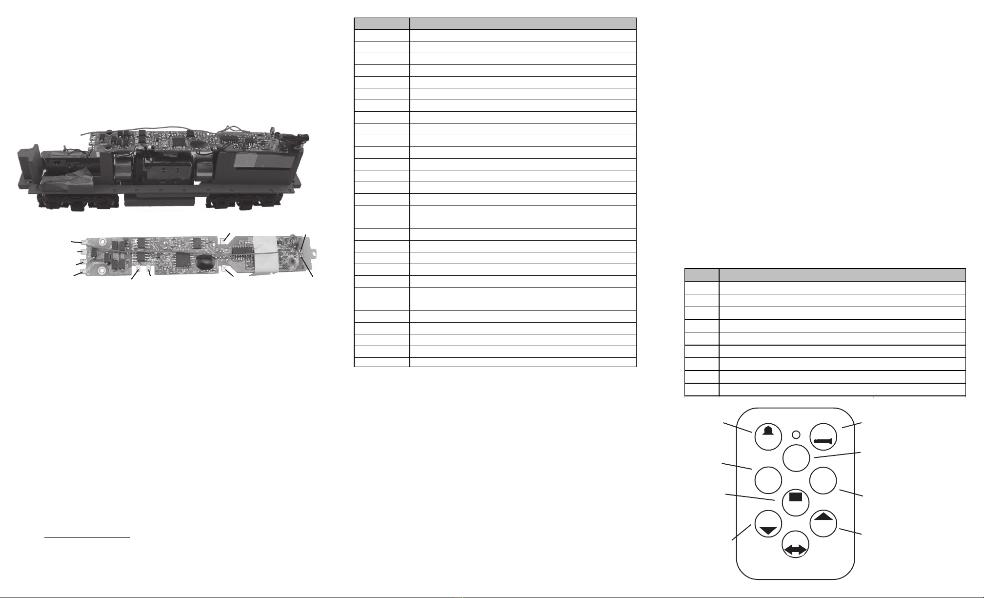
For Walthers GP15-1
Item #0001750 (with wireless remote)
Thank you for purchasing this MRC DC/DCC Diesel sound
decoder. It is a drop-in decoder designed for Walthers GP15-
1. The prime mover sounds for this decoder were recorded
directly from the real prime mover for this type of locomotive.
All notching along with increased speeds were also part of the
recording process. Unlike some others, we do not use simply
increase volume or frequency of the prime mover sound to
simulate the notching process. The decoder has presets for
all of its functions, so no adjustments should be required.
However if you wish to make changes, this decoder has a full
range of options. So now go ahead and enjoy.
FEATURES
•1.5 amp capacity
•16 different horns and 8 bells
•Individual sound volume adjustment
•2-digit (1-127) and 4-digit (1-9999) addresses
• Programmable starting voltage and top end voltage
• Programmable acceleration and deceleration rates
• Full READBACK of all CV’s
• 14, 28, 128 speed steps
•Speed table (CV 67-94), Kick start (V65)
•Directional lighting (F0).
•Back EMF and load compensation control
•28 accessory functions (F1-F28)
•Supports advanced consisting (CV19)
• Supports programming on the main (OPS mode)
• Compatible with NMRA DCC standards
• Complies with Part 15 of FCC
• 16x36mm speaker with baffle
• Dimensions: 114.0mm x 18.0mm x 11.0mm
DC PROGRAMMING
Move the throttle to 60%. Turn off the power switch and wait 2 seconds. Press and
hold button #6 as you turn ON the power switch. When you hear “Program”, quickly
release button #6. Now you are in program mode.
You can follow the DC Program table to perform 30 programs in one programming
session. If you need more than 30 programs, turn off power and re-enter program
mode to start a new session. It takes 2 seconds to perform one program so always
wait 2 seconds before performing the next program.
TROUBLE SHOOTING
• If the decoder does not work, it may have simply lost its address. Please use
program track to program CV# 125 with value 1 to restore the decoder to
factory settings. This should bring the decoder to life with an address #3.
• If it does not have sound, use F12 to turn on the sound. F12 is sound on/off.
• Do not operate this decoder at a track voltage greater than 18volts.
• If the locomotive responds too slowly, you should clear its momentum by
reprogramming CV3 and CV4 to zero.
• If the speed is too fast at step 1, you should program start voltage, CV2 to
zero.
• If its top speed is too slow, program top voltage CV5 to 31.
• If your locomotive runs erratic or is not starting smoothly, you should clean the
track to improve electrical pickup.
• Refer to your DCC system manual to learn how to program, read back and
operate the decoder. For more information about registers/CVs and their
functions, please refer to the NMRA DCC Standard & Recommended Practices,
RP-9.2.2. This is available directly from the NMRA or their website at
www.nmra.org.
FCC COMPLIANCE
This device complies with part 15 of the FCC Rules. Operation is subject to the
following two conditions. (1) This device may not cause harmful interference, and
(2) This device must accept any interference received, including interference that
may cause undesired operation.
RETURN PROCEDURE
This decoder carries a 6 month warranty against factory defects. This warranty
does not include abuse, misuse, neglect, improper installation, or any
modifications made to this decoder, including but not limited to the removal of the
NMRA plug if applicable. If it should become necessary to return the decoder for
warranty repair/replacement, please include a copy of the original sales
receipt. Please include a letter (printed clearly) with your name, address, daytime
phone number, and a detailed description of the problem you are experiencing.
Please also include a check or a money order for $8.00 to cover return shipping
and handling. If the decoder is no longer considered under warranty, then please
include a check or a money order for $29.00 to cover the cost of repair or
replacement and the return shipping and handling. Be certain to return the
decoder only. Any questions regarding Warranty Policy can be directed
to our Customer Service Department by calling 732-225-6360 between the
hours of 8:30am and 6:00pm EST, or by emailing:
rrtech@modelrectifier.com
Send the decoder to:
Model Rectifier Corporation
Attn: Parts & Service
80 Newfield Avenue
Edison, NJ 08837-3817 U.S.A
CV Register Description Range Default
CV1 R1 Short address 1-127 3
CV2 R2 Start voltage 0-32 2
CV3 R3 Acceleration 0-32 5
CV4 R4 Deceleration 0-32 5
CV5 --- Top voltage 0-32 32
--- R6 Page number --- ---
CV29 R5 Basic configuration --- 2
CV7 R7 Manufacturer version number --- 25
CV8 R8 Manufacturer ID --- 143
CV17 --- Long address upper byte 192-231 192
CV18 --- Long address low er byte 0-255 3
CV19 --- Advanced consist address 0-127 0
CV49 Sound on/of f except horn that is alw ays on 0-1 1
CV50 --- Horn type (16 types) 0-15 8
CV51 --- Horn volume 0-3 3
CV52 --- Bell type (8 types) 0-7 7
CV53 --- Bell volume 0-3 2
CV54 --- Bell ring rate 0-50 3
CV55 --- Diesel rumble volume 0-3 3
CV56 --- Brake squeal volume 0-3 3
CV57 --- Dynamic brake volume 0-3 3
CV58 --- Air release volume 0-3 3
CV59 --- Air pump volume 0-3 3
CV60 --- Safety pop valve volume 0-3 3
CV61 --- Engine cooling f an volume 0-3 3
CV62 --- Coupling volume 0-3 3
CV64 --- Rail w heel clack 0-3 3
CV65 Kick start voltage 0-63 63
CV67-94 28 speed steps table w hile CV29.4=1 1-255 linear
CV105 --- User identification number 0-255 0
CV106 --- User identification number 0-255 0
CV113 --- Coupling fire volume 0-3 3
CV114 --- Brake release volume 0-3 0
CV115 --- Auto brake squeal enable/disable 0-1 1(enable)
CV122 --- Notch mode, 0=auto, 3=manual 0-3 0
CV124 Load compensate control enable 0-1 0(disable)
CV125 --- Programming to "1" w ill restore some CV's to
factory settings --- 0
0CV 2 1 - - - When CV21=0, f unctions follow its ow n address.
CV21=1, f unctions follow the consist address ---
INSTALLATION
Remove body shell. Remove rear light from its holder to expose screw. Unscrew and
remove the rear light holder. Disconnect all wires before removing the original PCB.
Mount the new speaker and decoder as shown below. Reinstall rear light holder.
Realign the PCB to the CHASSIS before tightening all screws. Follow the wiring
diagram to reconnect wires. There are two short wires (black and red) for connecting
the rear light. Please match the color to connect the rear light. We recommend you
solder wires for a more reliable connection. If you wish instead to use tab caps to
connect wires, please twist the wire end carefully and leave only 3 mm of stripped
wire. Please make sure no stripped wires touch any components on the decoder.
Failure to do so may damage the decoder.
Figure 1.
DCC OPERATION
The decoder should perform well without any programming. Its starting and top
voltages have been PRE-TUNED for your GP15 loco. All you need to do is set its
address. The factory setting is address #3.
The decoder has start up and shut down features. If the loco was previously shut
down, you have to start up the engine by pressing any function key. Once started,
you can use the throttle to control loco speed. You can use F0 to turn on/off headlight.
When you turn off headlight, the light will fade away, just like real headlight. To shut
down the engine you must bring the loco to idle and then press F8 three times.
The decoder can operate at very slow speeds. We have achieved 1.5 inches per
minute at factory with load control off and 128 speed steps. If you feel that the
starting speed is too slow, you can program the start voltage, CV2, to increase its
value. Always read back the CV value first before changing its value.
The decoder has 16 different horns and 8 different bells. You can use F19 to select
a horn and F18 to select a different bell sound. With MRC Prodigy Advance2or the
Prodigy Wireless, you can easily set up and access all the decoder’s 28 functions.
If you are not using a Prodigy DCC System and it does not provide access to all 28
NMRA functions, you may not be able to access all the features of the decoder and
have to use CV programming to set up the decoder.
The decoder default is set to automatic notching. You can program CV122 to 3 for
manual notching if you so desire. for realistic operation. And then use F9 to notch up
and use F8 to notch down.
If when using this decoder it becomes non responsive, it may have lost its address.
Please use the program track to program CV# 125 with value 1 to restore certain
CV’s to factory settings. Or you can also program the loco to address 3. This should
bring the decoder to life with an address #3.
There are many more features available with this decoder. Please refer to the CV
and function Chart to explore all features of this decoder.
SPEED TABLE CV67-CV94 FOR 28 SPEED STEPS
This feature can be a little difficult for first time users. However it is a nice option if
you wish to consist (lash) this locomotive with another model that has a different
speed range.
The speed table feature allows you to program every speed increment of all 28
speed steps. You can customize the speed curve. In order to use the speed table
control you have to set CV29’s bit 4 to 1.To get there, you can program CV29 to 18
for short address or to 50 for a long address). When you operate the loco at 28
speed steps, the decoder will use the speed table formed by CV67-CV94 to control
speed (motor voltage). {If you own a MRC Prodigy Express, Advance or Wireless
system we recommend you to order the MRC computer interface to program your
decoder’s speed table. JMRI software can be used for other systems}.
Now select throttle to 28 speed steps and operate your loco at speed step 1. Use
program CV on the main to change CV67’s value (1-255) to adjust step 1’s speed.
You may also need to adjust the kick voltage, CV65, to get a nice slow speed at
speed step 1. The kick voltage is the voltage kick in when the speed step changes
from 0 to 1. When done with CV67, select speed step 2 and program CV68. CV68’s
value must be greater than CV67’s. When done with CV67-CV94, use the read back
CV feature to make sure their values are in an increasing order.
Note: When using MRC Prodigy DCC or some other systems, programming in a
new address will automatically disable the speed table (because it sets CV29’s
bit 4 to “0”). Programming CV125 to 1 will also disable the speed table and re-
program CV67-CV94 to a default linear speed setting. If you have the MRC
software interface, you can read back the speed table and it will draw the
speed curve for you.
DC OPERATION
You can use the enclosed transmitter to speed up, slow down, change direction,
and stop the loco. You can also use the transmitter to control sounds such as
bell and horn.
The decoder can also be operated by a regular DC power pack. The loco will
start up around 7V or 60% throttle setting. You can use the power pack throttle
to control speed. However, once you use the enclosed handheld transmitter to
control loco speed, it will disable the power pack throttle. To enable the throttle
again you have to flip the direction switch on the power pack. The transmitter
does not work properly at lower voltages. We recommend you set 85% throttle
and use transmitter to control your loco. Note, the maximum speed possible
from the remote transmitter is based on the maximum setting of the power pack
throttle. If the power pack throttle is set 70%, then the maximum speed using the
remote will not reach the top speed. Lower throttle settings could reduce the
transmitter range. If the range needs to be extended, we recommend letting the
antenna touch the track during operation for more reliable control. Please avoid
pressing buttons too rapidly in sequence and also avoid pressing and holding
buttons. These precautions will provide optimal performance and battery life.
Please follow the DC function table to DC operation.
Speed up
4
3
Stop
Direction
Speed down
Air release
Horn
Bell
6
12
78
5
9
rail clack
Head light
Note: The
transmitter
operates on a
12V (A123)
battery,
readily found
in most stores
that sell
electronic
equipment.
Function Idle/Moving
F0 Headlight on/off
F1 Bell on/off
F2 Horn
F3 Air release
F4 Coupling 1
F5 Brake release (idle) / brake squeal (moving)
F6 idle shifting during idle
F7 Air hose firing/uncoupling lever
F8 Click 3 times during idle will shut down / notch down while CV122=3
F9 Engine cooling fan / notch up while CV122=3
F10 Rail wheel clack (only moving)
F11 Traction air compressor
F12 Sound on/off
F13 Air release
F14 Coupling 2
F15 Air pump
F16 Associated loco sound
F17 flange noise 1
F18 Change bell type (use F1 to turn off bell after adjustment)
F19 Horn type select (total 16 different horns)
F20 Reversal gear
F21 Change bell volume (use F1 to turn off bell after adjustment)
F22 Change horn volume
F23 Change diesel rumble volume
F24 air release
F25 flange noise 2
F26 flange noise 3
F27 sand drop
F28 air release
Button Running mode Program mode
Button1 Bell on/off Change bell
Button2 Horn Change horn
Button3 air release Change bell volume
Button4 idle shifting during idle, rail clack during moving Change horn volume
Button5 Stop Change brake volume
Button6 Light on/off
Button7 Reduce speed. Air release at zero speed reduce start voltage by 1
Button8 Increase speed, Air release at top speed increase start voltage by 1
Button9 change direction Sound on/off
Figure 2. Wiring diagram
Red pickup wire
Front LED red wire
LED black wire
Rear LED red wire
Rear LED black wire
Red motor wire Black motor wire
Red pickup wire
Black pickup wire Black pickup wire
speaker
speaker

Other MRC Media Converter manuals

MRC 0001956 User manual

MRC

MRC 0001956 User manual

MRC 0001907 User manual

MRC

MRC 0001907 User manual

MRC 0001611 User manual

MRC

MRC 0001611 User manual

MRC 1651 User manual

MRC

MRC 1651 User manual

MRC 0001629 User manual

MRC

MRC 0001629 User manual

MRC 0001802 User manual

MRC

MRC 0001802 User manual

MRC 0001958 User manual

MRC

MRC 0001958 User manual

MRC Sheer Brilliance 0001638 User manual

MRC

MRC Sheer Brilliance 0001638 User manual

MRC 0001869 User manual

MRC

MRC 0001869 User manual

MRC AD332 User manual

MRC

MRC AD332 User manual

MRC 0001820 User manual

MRC

MRC 0001820 User manual

MRC 0001952 User manual

MRC

MRC 0001952 User manual

MRC RSW-914 User manual

MRC

MRC RSW-914 User manual

MRC 0001817 User manual

MRC

MRC 0001817 User manual

MRC 0001821 User manual

MRC

MRC 0001821 User manual

MRC 0001960 User manual

MRC

MRC 0001960 User manual

MRC 0001902 User manual

MRC

MRC 0001902 User manual

MRC AD324 User manual

MRC

MRC AD324 User manual

MRC 0001822 User manual

MRC

MRC 0001822 User manual

MRC 0001806 User manual

MRC

MRC 0001806 User manual

MRC 0001636 User manual

MRC

MRC 0001636 User manual

MRC AD370 User manual

MRC

MRC AD370 User manual

MRC 0001922 User manual

MRC

MRC 0001922 User manual

MRC 0001658 User manual

MRC

MRC 0001658 User manual

Popular Media Converter manuals by other brands

HDCVT TECHNOLOGY HDV-BS11A user manual

HDCVT TECHNOLOGY

HDCVT TECHNOLOGY HDV-BS11A user manual

StarTech.com HD2VID2 quick start guide

StarTech.com

StarTech.com HD2VID2 quick start guide

PAC LOC PRO ADVANCED LPA-1.2 quick start guide

PAC

PAC LOC PRO ADVANCED LPA-1.2 quick start guide

Axxess AX-ALOC608 installation instructions

Axxess

Axxess AX-ALOC608 installation instructions

iLive IBD704B quick start guide

iLive

iLive IBD704B quick start guide

Atoll Electronique DAC300 owner's manual

Atoll Electronique

Atoll Electronique DAC300 owner's manual

Kramer VP-435 user manual

Kramer

Kramer VP-435 user manual

LuxCom 1000BASE-T operating manual

LuxCom

LuxCom 1000BASE-T operating manual

Marmitek Split TS14 user manual

Marmitek

Marmitek Split TS14 user manual

CTC Union IMC-1000MS-PH12 Quick installation guide

CTC Union

CTC Union IMC-1000MS-PH12 Quick installation guide

Baumer ATD 2A Installation and operating instruction

Baumer

Baumer ATD 2A Installation and operating instruction

Boston Acoustics Horizon TRio manual

Boston Acoustics

Boston Acoustics Horizon TRio manual

Kramer VP-551X user manual

Kramer

Kramer VP-551X user manual

Siko ProTool SGH10 quick start guide

Siko

Siko ProTool SGH10 quick start guide

marklin 60942 user manual

marklin

marklin 60942 user manual

AMP MPEG4000-D4 Hardware reference manual

AMP

AMP MPEG4000-D4 Hardware reference manual

Parker TWIN-N Series user manual

Parker

Parker TWIN-N Series user manual

Phoenix Contact MACX MCR-SL-CAC-12-I-UP Installation notes for electricians

Phoenix Contact

Phoenix Contact MACX MCR-SL-CAC-12-I-UP Installation notes for electricians

manuals.online logo
manuals.online logoBrands
  • About & Mission
  • Contact us
  • Privacy Policy
  • Terms and Conditions

Copyright 2025 Manuals.Online. All Rights Reserved.