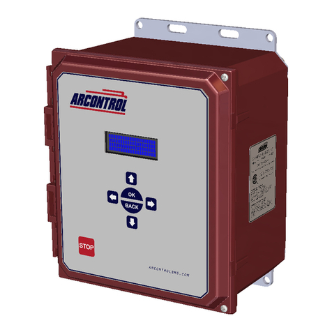
Cimarron ARCONTROL BMS User manual

USER MANUAL
ARCONTROL™ BMS
2019©Copyright Cimarron Energy
hps://www.arcontrolbms.com
Revision A
11/2019

Table of Contents
1 Introducon ................................................................................................................. 1
1.1 Hardware Installaon ........................................................................................................1
1.2 Wiring for Operaon .........................................................................................................6
1.3 Applicaon Informaon...................................................................................................11
2 System Overview .........................................................................................................12
2.1 User Interface .................................................................................................................. 12
2.2 System Splash Window.................................................................................................... 13
2.3 System Menu...................................................................................................................13
2.4 System Menu Symbols.....................................................................................................14
2.5 System Modes .................................................................................................................15
2.6 System States...................................................................................................................15
2.7 State Addional Informaon or Command .....................................................................19
2.8 Process 1 (P1), 2 (P2), 3 (P3) and INDEPENDENT (PI)........................................................20
2.9 Diagnosc Info & Diagnosc Mode .................................................................................21
3 System Sengs............................................................................................................24
3.1 Sengs Overview............................................................................................................24
3.2 Sengs Menu.................................................................................................................. 25
3.3 Changing System Sengs................................................................................................ 26
3.4 Seng Opons ................................................................................................................ 28
3.5 MODBUS Register Map.................................................................................................... 56
3.6 Data Logs .........................................................................................................................73
4 System Operaon ................................................................................................................. 76
4.1 AUTOMATIC Mode ..........................................................................................................76
4.2 MANUAL Mode ............................................................................................................... 79
4.3 Alarm & Shutdown States................................................................................................82
4.4 INDEPENDENT Process.................................................................................................... 84
4.5 PID Control Loop.............................................................................................................. 85
4.6 Transducer Calibraon.....................................................................................................85
4.7 USB Drive Port Funcons................................................................................................. 86
5 Troubleshoong....................................................................................................................... 87
6 Maintenance & Service............................................................................................................ 87
7 Equipment Rangs................................................................................................................... 88
8 Approvals ................................................................................................................................ 88
9 Unit Dimensions ...................................................................................................................... 89
9.1 ARControl Enclosure........................................................................................................ 89
9.2 BMS CID1 Enclosure ........................................................................................................90
10 BMS CID1 Enclosure Conduit Seal Placement ......................................................................... 91

WARNING!
1
1 Introducon
Thank you for purchasing the ARControl BMS Module, our most popular process control and ignion package.
This manual will provide you with important informaon that will help you understand the system, setup the system
and how the system operates. Please keep the manual in an accessible locaon for future reference. At Cimmaron
Energy Inc. we are always here to assist you with any service or spare part needs. Contact us at:
Phone: 1-844-746-1676
Website: hps://www.arcontrolbms.com
1.1 Hardware Installaon
The ARControl BMS should be installed according to the direcons provided in this manual and always be in compliance
with local electrical codes and the specicaons of the operang company. This secon will cover general instrucons
regarding safety as well as specic wiring and materials required for the safe and successful operaon of the ARControl
BMS.
1.1.1 Proper Use of the BMS Module 1870-511
The valve output on the BMS Module is the system’s ESD valve and is intended to be installed upstream of all other
valves in the ARControl BMS installaon. The dual-probe thermocouple input on the BMS Module is intended to be
used as the source for the high-temperature cuto. If the BMS Module 1870-511 is used in a manner not specied by
Cimarron Energy, Inc., the protecon provided by the equipment may be impaired.
Failure to comply with the following safety warning(s) may result in serious personal injury or death.
• Ensure the power is not connected unl the nal step of installaon.
• Failure of the grounding system integrity can result in personal injury, damage, or failure of operaon.
The equipment must be grounded in accordance with instrucons and devices and wiring connected to the
controller must be according to the appropriate electrical code
• Ensure that no personnel nor any objects come into contact with the ignion module, terminals, or damaged
coil wiring. The ignion coil can generate 38kV and is considered a hazard.
• If using an external power supply, do not power the ARControl with a supply rated for more than 24VDC.
Failure to comply with the following safety warning(s) may result in damage to the product.
• When installaon is complete, ensure that the enclosure is properly sealed and the fasteners are ght. The
enclosure will ensure that the internal components are not aected by moisture, ice, or debris.
• Disconnect and remove the baery during transportaon or when the ARControl will not be operated for
a period of me.
1.1.2 ARControl Installaon Guidelines
• A switch or circuit breaker must be included in the installaon; it must be suitably located and easily reached. It
must be marked as the disconnecng device for the equipment.
• Proper earth grounding per local electrical codes must be ulized in the installaon.
• If the ARControl is used in a manner not specied by Cimarron Energy, Inc., the protecon provided by the
equipment may be impaired.
• If the BMS Module (1870-511) is used in conjuncon with the ARControl it must be mounted externally of the
ARControl in order for the ARControl to remain regulatory compliant.
• Use the hardware supplied with the ARControl. The hardware kit supplied with the ARControl contains an
aluminum pre-drilled mounng bracket, and (4) 3/4-inch bolts and nuts.
NOTICE

2
• Locate the unit out of trac and working areas, away from excessive heat, and above areas where water and
liquids may accumulate. Visibility of the display will be enhanced if not facing direct sun.
• Measure the wiring distance. The ignion cable is restricted to a length of 25 feet maximum.
1.1.3 ARControl BMS Installaon
Follow these steps to install the ARControl BMS (opons for DIN mount or CID1, temperature or pressure control):
WARNING: Do not apply power to the system unl instructed to do so in step 16. Failure to comply may result in
serious personal injury or death.
1. Locate and open the hardware kit.
2. Aach the mounng anges to the back of the ARControl (1960-155) with the supplied hardware.
3. Drill holes in the boom of the enclosure to accommodate the cables and conduit to the unit. It is recommended
to use a step drill bit to drill the holes.
4. Mount the ARControl via the anges to a secure locaon and away from heat sources.
5. Mount provided ignion rod assembly to the pilot or burner assembly.
6. When installing the BMS Module with included DIN bracket (1960-171) inside of the ARControl:
a. Aach provided cable conduit using provided glands to enclosure and burner chamber.
b. Mount the ignion module to the DIN rail on the inside of the enclosure. WARNING: Mounng ignion
module inside enclosure VOIDS the 1960-155 ARControl Class I Division 2 rang.
c. Wire the ignion module to the ARControl’s MODULE PORT using the provided wiring harness.
7. When installing the BMS Module with Class 1 Division 1 enclosure (1960-170) external from the ARControl:
a. Mount the BMS Module enclosure near the burner of the process equipment.
b. Aach suitable cable conduit between the ARControl and BMS Module.
c. Aach suitable cable conduit between the BMS Module and burner chamber.
d. Wire the ignion module to the ARControl’s MODULE PORT using suitable 4-conductor cable (Image 1.1.1).
8. Connect the ignion wire to the tab of the BMS Module spark transformer, run it through the conduit and
aach it to ignion rod assembly.
9. Aach the free end of the grounding wire (green wire with yellow trace) to the burner’s chassis.
10. Install dual-probe thermocouple (148197) in process equipment or combustor stack.
11. Wire dual-probe thermocouple to the BMS Module’s thermocouple ports using k-type thermocouple
extension wire.
12. If using Pressure Control (old SAU funconality), install 0-5 psig transducer (8100-020) in the process gas stream
and wire the transducer to the ARControl Transducer Port (Image 1.1.1).
13. Install the ESD valve upstream of the pilot and process valves and wire the ESD valve to the VALVE output of the
BMS Module.
14. Install the pilot valve upstream of the pilot and wire the pilot valve to the Pilot Valve output of the ARControl.
15. Install the process 1 valve upstream of the burner and wire the process 1 valve to the Process 1 Valve output of
the ARControl.
16. Connect the power source to the power and ground terminal blocks.
17. If using Pressure Control (old SAU funconality w/ Barksdale 8100-020), navigate to SETTING MENU >
PROCESS 1 and set the following:
• SOURCE to XDCR
• LOGIC to ↑ ON ↓ OFF
• HIGH LEVEL to 50
• LOW LEVEL to 20

5
Y+ R-
POWER
VALVE
OUTRET
RS485
A B
TC1
Y+ R-
TC2
VLV B
DIN
GND
PS3
GND
PS2
GND
PS1
PWR
A B PWR GND
MODULE PORT
IN+
IN-
GND
R-
B-
A+
Y+
GND
Y+
R-
THERMO-
COUPLE
PORT
RS485
PORT
ALARM
OUTPUT
DOUT-
DOUT-
AUXIO
GND
DOUT+
GND
OPN-G
GND
CLS-R
OPN-G
GND
CLS-R
MAIN
VALVE
BATTERY-IN
GND
SOLAR
GND
PWR-OUT
BATTERY-OUT
PILOT
VALVE
POWER
PORT
DIGITAL
OUTPUTS
GND GND
GROUND
GND GND
DIGITAL
INPUTS
TRANS-
DUCER
PORT
TC2
TC1
MAIN
VLV A
PILOT
Permissive +
-
Proof of Closure +
-
PS2
PS1
ARControl BMS
Thermocouple 1 R-
Y+
Thermocouple 2 R-
Y+
Alarm -
+
Independent
Process Valve
+
-
Pilot Status +
-
+
-
+
Process 1 Valve
Process 2 Valve
+
-
+
Pilot Valve
Process 3 Valve
+
-
+
Transducer
Port
GND
B-
A+
Modbus
RS-485
PWR
+
-
GND
3
Permissive IN
(jump closed
if not in use)
To Pilot Igniter
Ignion Wire
Important!
I/O board sckers.
Replace when
missing.
Burner Stack
Source Gas
7
10
8
Pilot Status OUT
(oponal)
12 or
24VDC
Power IN
Modbus RS-485
(oponal)
ESD Valve
Source
Gas
To Pilot
To Burner
Process 1 Valve
Pilot Valve
13
14
15
Image 1.1.1 · BMS pressure process control wiring diagram
5
Y+ R-
POWER
VALVE
OUTRET
RS485
A B
TC1
Y+ R-
TC2

4
18. If using the High-temperature shutdown feature, navigate to SETTING MENU > BMS MODULE >
TEMP LIMIT to set the high-temperature shutdown temperature.
19. If using Temperature Control (old Torch funconality) (Image 1.2.2), navigate to SETTING MENU > PROCESS 1
and set:
• SOURCE to TC BMS
• LOGIC to ↑ OFF ↓ ON
• HIGH LEVEL to high process temperature
• LOW LEVEL to low process temperature
20. Navigate to the START (HOLD OK) menu entry on the home screen and hold the OK key for at least a
second. This will start the ignion sequence and process control.

5
Y+ R-
POWER
VALVE
OUTRET
RS485
A B
TC1
Y+ R-
TC2
5
VLV B
DIN
GND
PS3
GND
PS2
GND
PS1
PWR
A B PWR GND
MODULE PORT
IN+
IN-
GND
R-
B-
A+
Y+
GND
Y+
R-
THERMO-
COUPLE
PORT
RS485
PORT
ALARM
OUTPUT
DOUT-
DOUT-
AUXIO
GND
DOUT+
GND
OPN-G
GND
CLS-R
OPN-G
GND
CLS-R
MAIN
VALVE
BATTERY-IN
GND
SOLAR
GND
PWR-OUT
BATTERY-OUT
PILOT
VALVE
POWER
PORT
DIGITAL
OUTPUTS
GND GND
GROUND
GND GND
DIGITAL
INPUTS
TRANS-
DUCER
PORT
TC2
TC1
MAIN
VLV A
PILOT
Permissive +
-
Proof of Closure +
-
PS2
PS1
Transducer
Port
ARControl BMS
Thermocouple 1 R-
Y+
Thermocouple 2 R-
Y+
Alarm -
+
Independent
Process Valve
+
-
Pilot Status +
-
+
-
+
Process 1 Valve
Process 2 Valve
+
-
+
Pilot Valve
Process 3 Valve
GND
B-
A+
Modbus
RS-485
+
-
+
PWR
+
-
GND
Permissive IN
(jump closed
if not in use)
Image 1.1.2 · BMS temperature process control wiring diagram
Pilot Status OUT
(oponal)
12 or
24VDC
Power IN
To Pilot Igniter
Ignion Wire
Important!
I/O board sckers.
Replace when
missing.
Modbus RS-485
(oponal)
Vessel Bath
ESD Valve
Source
Gas
To Combustor
Pilot
To Combustor
Burner
Process 1 Valve
Pilot Valve
7
10
8
13
14
15
5
Y+ R-
POWER
VALVE
OUTRET
RS485
A B
TC1
Y+ R-
TC2

6
DIN
GND
PS3
GND
PS2
GND
PS1
PWR
A B PWR GND
MODULE PORT
IN+
IN-
GND
R-
B-
A+
Y+
GND
Y+
R-
THERMO-
COUPLE
PORT
RS485
PORT
ALARM
OUTPUT
DOUT-
DOUT-
AUXIO
GND
DOUT+
GND
OPN-G
GND
CLS-R
OPN-G
GND
CLS-R
MAIN
VALVE
BATTERY-IN
GND
SOLAR
GND
PWR-OUT
BATTERY-OUT
PILOT
VALVE
POWER
PORT
DIGITAL
OUTPUTS
GND GND
GROUND
GND GND
DIGITAL
INPUTS
TRANS-
DUCER
PORT
5 Watt Solar
Panel
1.2 Wiring for Operaon
This secon covers general wiring for most common
applicaons. Important! All wiring should be done
in accordance with local regulaons and within the
specicaons of the site or equipment owner. If there
are quesons not answered by this manual or the wiring
diagrams, please call Cimarron Energy at 1-844-746-1676
for assistance.
1.2.1 Connecng the Power
The ARControl is designed to operate from either 12 or 24
volt power supplies or baeries. Power supplies should
be rated Class II and capable of sourcing a minimum of 2
amps. Baeries should be either 12 or 24 volt and have a
minimum 12 Ah (amp-hour) capacity.
1.2.2 Connecng a Solar Panel and Baery
(if required)
Solar Charing
The ARControl contains an integrated solar charger. The
solar charger is capable of charging a 12 volt 12 Ah SLA
(sealed lead acid) baery. A solar panel rated for 12 volt
systems with a maximum current output of 2 amps is
recommended. Installaons that require more charging
current than provided by the internal solar charger should
ulize a properly sized external solar charger and baery
(Image 1.2.1).
Power Pack
The standard ARControl Power Pack (PN: 1960-160)
contains a 12 volt 12 Ah SLA baery in a sturdy DIN-
mountable bracket and a 5 wa 12 volt solar panel with
9 feet of cable and a mounng bracket. The baery and
bracket clips onto the boom DIN rail in the ARControl
enclosure. The solar panel can be mounted with a U-bolt
to a pole or to any other structure that
can accommodate the mounng holes. Be sure to
locate the solar panel south facing in an area free from
obstrucon of the sun throughout the enrety of the day
(Image 1.2.2).
Fusing
The ARControl has three user-replaceable fuses. The fuse
on the DIN rail mounted terminal block that connects to
BATTERY IN on the ARControl ulizes a 5 amp ATC or ATO
fuse. The ARControl board is fused at both the POWER
PORT and MODULE PORT with 2 amp ceramic fuses (PN:
3181-002). The POWER PORT fuse protects all of the valve
outputs and the digital outputs. The MODULE PORT fuse
protects the power output to the Ignion Module. There
are two spare 2 amp ceramic fuses located in the SPARE
FUSES locaon on the ARControl board.
DIN
GND
PS3
GND
PS2
GND
PS1
PWR
A B PWR GND
MODULE PORT
IN+
IN-
GND
R-
B-
A+
Y+
GND
Y+
R-
THERMO-
COUPLE
PORT
RS485
PORT
ALARM
OUTPUT
DOUT-
DOUT-
AUXIO
GND
DOUT+
GND
OPN-G
GND
CLS-R
OPN-G
GND
CLS-R
MAIN
VALVE
BATTERY-IN
GND
SOLAR
GND
PWR-OUT
BATTERY-OUT
PILOT
VALVE
POWER
PORT
DIGITAL
OUTPUTS
GND GND
GROUND
GND GND
DIGITAL
INPUTS
TRANS-
DUCER
PORT
Chassis
Ground
Sealed Lead Acid
Battery (SLA)
Positive terminal can be
connected from the
power source to the
fused DIN rail mounted
terminal block
5 A
Image 1.2.1 · Solar panel wiring
Image 1.2.2 · Baery pack wiring

7
1.2.3 PERMISSIVE (DIN) Input
The PERMISSIVE input is used to
shutdown the system if it is acve.
Connect the input to a PLC or some
other external switch. By default,
the input is acve when the circuit is
open but this can be changed in the
IO sengs. It is internally pulled up to
5 VDC. If it is not used it needs to be
jumpered (Image 1.2.3).
1.2.4 Proof of Closure Input
The PROOF OF CLOSURE input is used
to check that a valve is closed before
the system aempts to ignite.
Important! Failure of this test will
transion the system to the POC
FAILURE state.
Connect the input to a valve’s status
output, pressure switch, or other
device intended to prove the state of
the valve. By default, it is acve when
the circuit is open but this can be
changed in the IO sengs. The input
is internally pulled up to 5 VDC. If this
input is not being used it needs to be
jumpered (Image 1.2.4).
1.2.5 Pressure Switches PS1
& PS2
The Pressure Switch inputs, PS1
& PS2, are generic digital inputs.
They can be used as sources for the
Shutdowns.
By default, they are acve when the
circuit is open but this can be changed
in the IO sengs. They are internally
pulled up to 5 VDC (Image 1.2.5).
DIN
GND
PS3
GND
PS2
GND
PS1
PWR
A B PWR GND
MODULE PORT
IN+
IN-
GND
R-
THERMO-
COUPLE
PORT
DIGITAL
INPUTS
TRANS-
DUCER
PORT
TC2
Permissive +
-
Proof of Closure +
-
PS2
PS1
Transducer
Port
+
-
+
PWR
+
-
GND
IN
GND
5VDC 1MΩ
10KΩ
DIN
GND
PS3
GND
PS2
GND
PS1
PWR
A B PWR GND
MODULE PORT
IN+
IN-
DIGITAL
INPUTS
TRANS-
DUCER
PORT
Permissive +
-
Proof of Closure +
-
PS2
PS1
Transducer
Port
PWR
+
-
GND
Permissive IN
GND
+
-
+
DIN
GND
PS3
GND
PS2
GND
PS1
PWR
A B PWR GND
MODULE PORT
IN+
IN-
GND
R-
B-
A+
Y+
GND
Y+
R-
THERMO-
COUPLE
PORT
RS485
PORT
DIGITAL
INPUTS
TRANS-
DUCER
PORT
TC2
TC1
Permissive +
-
Proof of Closure +
-
PS2
PS1
Transducer
Port
Hot Surface
Thermocouple 1
R-
Y+
Hot Surface
Thermocouple 2
R-
Y+
GND
B-
A+
Modbus
RS-485
+
-
+
PWR
+
-
GND
Image 1.2.3 · PERMISSIVE input wiring
Image 1.2.4 · Proof of closure input wiring
Image 1.2.5 · Pressure switch input wiring
Note: If Pressure Switches
are not used they should be
jumpered

DIN
GND
PS3
GND
PS2
GND
PS1
PWR
A B PWR GND
MODULE PORT
IN+
IN-
GND
R-
B-
A+
Y+
GND
Y+
R-
THERMO-
COUPLE
PORT
RS485
PORT
DIGITAL
INPUTS
TRANS-
DUCER
PORT
TC2
TC1
Permissive +
-
Proof of Closure +
-
PS2
PS1
Transducer
Port
Transducer
Hot Surface
Thermocouple 1
R-
Y+
Hot Surface
Thermocouple 2
R-
Y+
GND
B-
A+
Modbus
RS-485
+
-
+
PWR
+
-
GND
8
1.2.6 Transducer Port Input
The Transducer Port input accepts
mulple dierent transducer types.
The Transducer Port input can be
used as a source for the Processes
and Shutdowns (Image 1.2.6).
1.2.7 Thermocouple
Inputs 1 & 2
Thermocouple inputs 1 & 2 accept
k-type thermocouples. They can be
used as sources for the Processes and
Shutdowns. If they are not used they
need to be jumpered (Image 1.2.7).
1.2.8 Modbus RS-485
To use Modbus communicaon,
use the RS-485 PORT on the board,
aaching the A+ and B- wiring as well
as the GND to the external PLC or
communicaon device. Nocaons
of alarms can also be retrieved via
Modbus (Image 1.2.8).
VLV B
DIN
GND
PS3
GND
PS2
GND
PS1
PWR
A B PWR GND
MODULE PORT
IN+
IN-
GND
R-
B-
A+
Y+
GND
Y+
R-
THERMO-
COUPLE
PORT
RS485
PORT
ALARM
OUTPUT
DOUT-
DOUT-
AUXIO
GND
DOUT+
GND
OPN-G
GND
CLS-R
OPN-G
GND
CLS-R
MAIN
VALVE
BATTERY-IN
GND
SOLAR
GND
PWR-OUT
BATTERY-OUT
PILOT
VALVE
POWER
PORT
DIGITAL
OUTPUTS
GND GND
GROUND
GND GND
DIGITAL
INPUTS
TRANS-
DUCER
PORT
TC2
TC1
MAIN
VLV A
PILOT
ARControl BMS
Alarm -
+
Independent
Process Valve
+
-
Pilot Status +
-
+
-
+
Process 1 Valve
Process 2 Valve
+
-
+
Pilot Valve
Process 3 Valve
Customer External PLC
Permissive +
-
Proof of Closure +
-
PS2
PS1
Transducer
Port
Hot Surface
Thermocouple 1
R-
Y+
Hot Surface
Thermocouple 2
R-
Y+
GND
B-
A+
Modbus
RS-485
PWR
+
-
GND
+
-
+
Image 1.2.8 · Modbus RS-485 wiring
Image 1.2.7 · Thermocouple (TC1 & TC2) input wiring
Image 1.2.6 · Transducer port input wiring
VLV B
DIN
GND
PS3
GND
PS2
GND
PS1
PWR
A B PWR GND
MODULE PORT
IN+
IN-
GND
R-
B-
A+
Y+
GND
Y+
R-
THERMO-
COUPLE
PORT
RS485
PORT
ALARM
OUTPUT
DOUT-
DOUT-
AUXIO
GND
DOUT+
GND
OPN-G
GND
CLS-R
OPN-G
GND
CLS-R
MAIN
VALVE
BATTERY-IN
GND
SOLAR
GND
PWR-OUT
BATTERY-OUT
PILOT
VALVE
POWER
PORT
DIGITAL
OUTPUTS
GND GND
GROUND
GND GND
DIGITAL
INPUTS
TRANS-
DUCER
PORT
TC2
TC1
MAIN
VLV A
PILOT
Thermocouple 1 & 2
ARControl BMS
Alarm -
+
Independent
Process Valve
+
-
Pilot Status +
-
+
-
+
Process 1 Valve
Process 2 Valve
+
-
+
Pilot Valve
Process 3 Valve
+
-
+
Permissive +
-
Proof of Closure +
-
PS2
PS1
Transducer
Port
Hot Surface
Thermocouple 1
R-
Y+
Hot Surface
Thermocouple 2
R-
Y+
GND
B-
A+
Modbus
RS-485
PWR
+
-
GND

9
1.2.9 Pilot Status Output
The Pilot Status output indicates if the
system is detecng ame at the pilot.
This output can drive and indicator
light or interface with an external
PLC. The output voltage is the same
as BATTERY-IN. The combined current
output of Pilot Status and all of the
valves is 2 A MAX (Image 1.2.9).
1.2.10 Valves Pilot, Process
1, Process 2, Process 3, and
Independent Process
The valve outputs are intended to
drive solenoid valves. They have user-
adjustable peak-and-hold capability.
The output voltage is the same as
BATTERY-IN. The combined current
output of Pilot Status and all of the
valves is 2 A MAX (Image 1.2.10).
VLV B
DIN
GND
PS3
GND
PS2
GND
PS1
PWR
A B PWR GND
MODULE PORT
IN+
IN-
GND
R-
B-
A+
Y+
GND
Y+
R-
THERMO-
COUPLE
PORT
RS485
PORT
ALARM
OUTPUT
DOUT-
DOUT-
AUXIO
GND
DOUT+
GND
OPN-G
GND
CLS-R
OPN-G
GND
CLS-R
MAIN
VALVE
BATTERY-IN
GND
SOLAR
GND
PWR-OUT
BATTERY-OUT
PILOT
VALVE
POWER
PORT
DIGITAL
OUTPUTS
GND GND
GROUND
GND GND
DIGITAL
INPUTS
TRANS-
DUCER
PORT
TC2
TC1
MAIN
VLV A
PILOT
ARControl BMS
Alarm -
+
Independent
Process Valve
+
-
Pilot Status +
-
+
-
+
Process 1 Valve
Process 2 Valve
+
-
+
Pilot Valve
Process 3 Valve
Status OUT
2A
12 or 24
VDC
OUT
GND
GND
+
-
+
Permissive +
-
Proof of Closure +
-
PS2
PS1
Transducer
Port
Hot Surface
Thermocouple 1
R-
Y+
Hot Surface
Thermocouple 2
R-
Y+
GND
B-
A+
Modbus
RS-485
PWR
+
-
GND
VLV B
DIN
GND
PS3
GND
PS2
GND
PS1
PWR
A B PWR GND
MODULE PORT
IN+
IN-
GND
R-
B-
A+
Y+
GND
Y+
R-
THERMO-
COUPLE
PORT
RS485
PORT
ALARM
OUTPUT
DOUT-
DOUT-
AUXIO
GND
DOUT+
GND
OPN-G
GND
CLS-R
OPN-G
GND
CLS-R
MAIN
VALVE
BATTERY-IN
GND
SOLAR
GND
PWR-OUT
BATTERY-OUT
PILOT
VALVE
POWER
PORT
DIGITAL
OUTPUTS
GND GND
GROUND
GND GND
DIGITAL
INPUTS
TRANS-
DUCER
PORT
TC2
TC1
MAIN
VLV A
PILOT
ARControl BMS
Alarm -
+
Independent
Process Valve
+
-
Pilot Status +
-
+
-
+
Process 1 Valve
Process 2 Valve
+
-
+
Pilot Valve
Process 3 Valve
Valve B
Pilot Valve
Valve A
Main Valve
2A
12 or 24
VDC
OUT
GND
Permissive +
-
Proof of Closure +
-
PS2
PS1
Transducer
Port
Hot Surface
Thermocouple 1
R-
Y+
Hot Surface
Thermocouple 2
R-
Y+
GND
B-
A+
Modbus
RS-485
+
-
+
PWR
+
-
GND
Image 1.2.9 · Pilot status output wiring
Image 1.2.10 · Valve pilot, process 1, 2, 3 and Independent wiring

10
1.2.11 BMS Module Valve
The BMS Module valve output is
intended to drive the ESD valve. It
has user-adjustable peak-and-hold
capability. The output voltage is the
same as POWER IN+. The maximum
current output is 2 amps (Image
1.2.11).
1.2.12 BMS Module
Thermocouple Inputs
TC1 & TC2
Thermocouple inputs TC1 &
TC2 accept a dual-probe k-type
thermocouple. They are not to be
used for separate thermocouples.
It can be used as a source for the
Processes and Shutdowns. It is
always used for the high-temperature
shutdown, TEMP LIMIT. If a dual-
probe thermocouple is not being
used, TC1 & TC2, individually, need to
be jumpered. (Image 1.2.12).
VLV B
DIN
GND
PS3
GND
PS2
GND
PS1
PWR
A B PWR GND
MODULE PORT
IN+
IN-
GND
R-
B-
A+
Y+
GND
Y+
R-
THERMO-
COUPLE
PORT
RS485
PORT
ALARM
OUTPUT
DOUT-
DOUT-
AUXIO
GND
DOUT+
GND
OPN-G
GND
CLS-R
OPN-G
GND
CLS-R
MAIN
VALVE
BATTERY-IN
GND
SOLAR
GND
PWR-OUT
BATTERY-OUT
PILOT
VALVE
POWER
PORT
DIGITAL
OUTPUTS
GND GND
GROUND
GND GND
DIGITAL
INPUTS
TRANS-
DUCER
PORT
TC2
TC1
MAIN
VLV A
PILOT
ARControl BMS
Alarm -
+
Independent
Process Valve
+
-
Pilot Status +
-
+
-
+
Process 1 Valve
Process 2 Valve
+
-
+
Pilot Valve
Process 3 Valve
+
-
1 2 3 4
ROCKER DOWN
O
F
F
VALVE
OUTRET
POWER RS485
B
A
TC1
R-
Y+
TC2
R-
Y+
1870-511
Permissive +
-
Proof of Closure +
-
PS2
PS1
Transducer
Port
Hot Surface
Thermocouple 1
R-
Y+
Hot Surface
Thermocouple 2
R-
Y+
GND
B-
A+
Modbus
RS-485
+
-
+
PWR
+
-
GND
Image 1.2.11 · BMS Module valve output wiring
Image 1.2.12 · BMS Module thermocouple inputs TC1 & TC2
ESD Valve

FROM MCU
DOUT+
DOUT-
36R0 50mA
PTC
DIN
GND
PS3
GND
PS2
GND
PS1
PWR
A B PWR GND
MODULE PORT
IN+
IN-
GND
R-
B-
A+
Y+
GND
Y+
R-
THERMO-
COUPLE
PORT
RS485
PORT
ALARM
OUTPUT
DOUT-
DOUT+
AUXIO
GND
DOUT+
GND
OPN-G
GND
CLS-R
OPEN-G
GND
CLS-R
MAIN
VALVE
BATTERY-IN
GND
SOLAR
GND
PWR-OUT
BATTERY-OUT
PILOT
VALVE
POWER
PORT
DIGITAL
OUTPUTS
GND GND
GROUND
GND GND
DIGITAL
INPUTS
TRANS-
DUCER
PORT
11
1.3 Applicaon Informaon
1.3.1 Alarm Output
The Alarm output indicates if the
system is in an abnormal state such as a
Shutdown or PILOT FAILURE. The output
behaves as a switch. By default, it is
closed when there is no alarm condion
but this can be changed in the IO
sengs. External alarm circuitry should
be limited to 50mA (Image 1.3.1).
OUT TO
AUTOMATION
PLC
Alarm output inacve/closed switch circuit diagram
Image 1.3.1 · Alarm output inacve

STOP
OK
BACK
ARCONTROLBMS.COM
12
2 System Overview
2.1 User Interface
The system user interface (Image 2.1.1) consists of a text display and seven keys (Table 2.1.1) that are used for menu
navigaon, selecng opons on menu items and entering or exing menus.
The text display provides informaon regarding menus, submenus, system modes, selectable opons, current mode
operaon states and alarms. The text display features automac shuto aer 60 seconds without user interacon
through the keypad. The automac shuto feature helps save power which is especially important in remote
installaons that are solar powered.
Pressing any key will wake up the text display and bring it to the top of the Main menu. If the STOP key is pressed while
the text display is o, it will both send the unit in to the STOPPED state and wake up the text display. Addionally, if the
system enters into any of the alarm states this will also wake up the text display and it will bring the alarm state screen.
Text Display
Right Key
Down Key
Up Key
Le Key
OK Key
BACK Key
STOP Key
Image 2.1.1 ·System user interface
Table 2.1.1 ·User interface keys
KEY USE DESCRIPTION
Up Use to scroll up menu items
Down Use to scroll down menu items
Le Use to toggle through selectable opons Selectable opons are shown between angle brackets < >
Right Use to toggle through selectable opons Selectable opons are shown between angle brackets < >
OK Use to enter a submenu and select or
enter menu item choice
The OK key allows the entering of menu item acons
and choices, and to and accept or deny system
conrmaon screens.
BACK Use to exit a selected submenu or cancel /
deny prompts
STOP Use to put the system in STOP state The STOP key interrupts any current operaon and sends the
system to the STOPPED state.

A R C O N T R O L ™
F I R M W A R E 5 4 0 0 - 5 2 1 - X X
13
2.3 System Menu
The System Menu displays the current system state, addional informaon about the system state, the current values
of the processes, and the current operang mode. It also provides access to the Process Quick Set-up menu, Diagnoscs
Informaon, Sengs, and Service Info menus (Table 2.3.1).
The addional state informaon consists of state countdowns, state duraons, and commands to interact with the
system. The informaon that is displayed depends on which state the system is in. The System Menu is shown in the
text display (Image 2.3.1) and displays the following:
• Current system state
• Addional informaon about the current system state and prompts for aconable menu items
• Current value of Process 1 (select to access the process 1 quick set-up menu)
• Current value of Process 2 (select to access the process 2 quick set-up menu)
• Current value of Process 3 (select to access the process 3 quick set-up menu)
• Current value of Process Independent (select to access the process Independent quick set-up menu)
• Current mode (select to toggle between AUTOMATIC and MANUAL modes)
• Diagnoscs informaon (select to navigate to diagnosc informaon and aconable items)
• Sengs Menu (select to navigate to seng submenus)
• Service Info (select to navigate to service informaon)
2.2 System Splash Window
When the system powers up the System Splash window (Image 2.2.1) will appear for 2 seconds. The splash window
contains the product’s name and the system’s rmware idencaon version number and revision level.
Firmware revision level
Image 2.2.1 · System splash window
Table 2.3.1 ·System menu items
MENU ITEM FUNCTION
CURRENT STATE Reports the system current state of operaon. The reported state varies as a funcon of the
current system mode.
STATE ADDITIONAL
INFORMATION OR
COMMAND
Reports addional informaon about the current state of the system. This addional
informaon include countdown, duraon of the system in the current state and acon the
user can take at the current state.
PROCESS 1, 2, 3 AND
INDEPENDENT
Display the current process variable value and units for a process. Addionally, this entry
navigates to the process’ quick set menu where high and low level can be set within
allowable ranges.
MODE Reports the systems current mode of operaon (AUTOMATIC or MANUAL)
DIAGNOSTICS INFO
Navigates into a the diagnoscs info menu which displays the state of each input and output.
The Diagnosc Mode menu is the last item in the Diagnosc Info Menu, it allows the user to
toggle the outputs in order to test the system.
SETTINGS MENU Navigates into sengs menu
SERVICE INFO Navigates service and diagnosis informaon menu

STOP
OK
BACK
ARCONTROLBMS.COM
E T T I N S
I
M
N
E N
S
S
E R V I C E
G
F O
U
I N F O
M O D E =
S T A T E =
[ C U R R
[ C U R R
[ C U R R
[ C U R R
[ S T A T E A D D T L I N F O ]
V A L U E ]
V A L U E ]
D I A G N O S T I C S
P₂=
P₃=
P
I=
P₁=
V A L U E ]
V A L U E ]
A U T M A T I C
O
P P ES T O D
→
≡
≡
≡
≡
≡
≡
≡
E T T I N S
I
M
N
E N
S
S
E R V I C E
G
F O
U
I N F O
→
M O D E =
S T A T E :
[ C U R R
[ C U R R
[ C U R R
[ C U R R
[ S T A T E A D D T L I N F O ]
V A L U E ]
V A L U E ]
D I A G N O S T I C S
P₂=
P₃=
P
I=
P₁=
V A L U E ]
V A L U E ]
A N U A L
M
P P ES T O D
≡
≡
≡
≡
≡
≡
≡
→
[ ]
X X X X X X . X
≡
< >
→
[ ]
X X X X X X . X
≡
< >
→
[ ]
X X X X X X . X
≡
< >
→
[ ]
X X X X X X . X
≡
< >
→
[ ]
X X X X X X . X
≡
< >
→
[ ]
X X X X X X . X
≡
< >
E T T I N S
I
M
N
E N
S
S
E R V I C E
G
F O
U
I N F O
→
MM O D E = [ C U R R E N T O D E ]
S T A T E = [ C U R R
[ C U R R
[ C U R R
[ C U R R
[ C U R R
S T A T E ]
[ S T A T E A D D T L I N F O ]
V A L U E ]
V A L U E ]
D I A G N O S T I C S
P₂=
P₃=
P
I=
P₁=
V A L U E ]
V A L U E ]
≡
≡
≡
≡
≡
≡
≡
14
Indicates current menu selecon
Indicates a submenu
Indicates an aconable menu item
Indicates dynamic text related to user selecon
Indicates a user selectable opon
Indicates placeholders for numerical values
The following is an example of using the System Menu:
Example: Changing the operaon mode from AUTOMATIC to MANUAL mode (Image 2.3.2).
1. Use the UP or DOWN key and select MODE.
2. Press the OK key.
3. Using LEFT and RIGHT key scroll to the MANUAL menu entry.
4. Press the OK key. The system will now be in the MANUAL mode. Note: The current state of the mode is
shown in the STATE row.
2.4 System Menu Symbols
The symbols shown in the System Menu signify the following:
Use the UP or DOWN key
and move arrow to MODE
Scroll to MANUAL
13
2
4
Image 2.3.2 · Change operaon mode
Current mode
Image 2.3.1 ·System menu
Current state
Sengs submenu
Service info
submenu
Addional Info
Current value:
process 2
Current value:
process 1
Current value:
process 3 Current value:
process Independent
Diagnoscs
informaon

E T T I N S
I
M
N
E N
S
S
E R V I C E
G
F O
U
I N F O
M O D E =
S T A T E =
[ C U R R
[ C U R R
[ C U R R
[ C U R R
[ S T A T E A D D T L I N F O ]
V A L U E ]
V A L U E ]
D I A G N O S T I C S
P₂=
P₃=
P
I=
P₁=
V A L U E ]
V A L U E ]
A U T M A T I C
O
P P ES T O D
→
≡
≡
≡
≡
≡
≡
≡
E T T I N S
I
M
N
E N
S
S
E R V I C E
G
F O
U
I N F O
→
M O D E =
S T A T E :
[ C U R R
[ C U R R
[ C U R R
[ C U R R
[ S T A T E A D D T L I N F O ]
V A L U E ]
V A L U E ]
D I A G N O S T I C S
P₂=
P₃=
P
I=
P₁=
V A L U E ]
V A L U E ]
A N U A L
M
P P ES T O D
≡
≡
≡
≡
≡
≡
≡
E T T I N S
I
M
N
E N
S
S
E R V I C E
G
F O
U
I N F O
M O D E =
S T A T E =
[ C U R R
[ C U R R
[ C U R R
[ C U R R
[ S T A T E A D D T L I N F O ]
V A L U E ]
V A L U E ]
D I A G N O S T I C S
P₂=
P₃=
P
I=
P₁=
V A L U E ]
V A L U E ]
A U T M A T I C
O
P P ES T O D
→
≡
≡
≡
≡
≡
≡
≡
15
2.5 System Modes
The system has two operaon modes, AUTOMATIC and MANUAL, to choose from. In AUTOMATIC mode (Image 2.5.1)
ignion is iniated by the user. Once the pilot is lit, the system will automacally start controlling the process and
aempt to relight the pilot if ame is lost. ON DEMAND mode is also available which only lights the pilot when ame is
required by a process. AUTOMATIC mode is the default system operaon mode.
In MANUAL mode (Image 2.5.2) the duraon of ignion is manually controlled by the user. Once the pilot is lit, the
user must iniate the process control. The system will not aempt to automacally relight if ame is lost. ON DEMAND
mode is not available in MANUAL mode operaon.
2.6 System States
Each system mode has mulple operaon states (Table 2.6.1 & 2.6.2) and alarm states (Table 2.6.3). The current
operaon state is displayed on the System Menu (Image 2.6.1). Upon power-up in AUTOMATIC mode, the system
inializes in the STOPPED state.
Note: An INDEPENDENT process runs independently of all other system states including alarm and shutdown states.
The INDEPENDENT process is only inacve in DIAGNOSTIC mode.
Image 2.5.1 · AUTOMATIC mode
Image 2.5.2 · MANUAL mode
Image 2.6.1 · Default operaon mode and state
Default state
Default mode

16
Table 2.6.1 · AUTOMATIC mode operaonal states
AUTOMATIC MODE OPERATIONAL STATES
STATE DISPLAY DESCRIPTION
STOPPED STOPPED
In the STOPPED state, the system closes all valves and acvates the ALARM output.
If ON DEMAND is disabled and the user iniates the system by pressing and holding
the OK buon for a second or more, the system will transion to the START-UP state.
If ON DEMAND is enabled and the user iniates the system by pressing and holding
the OK buon for a second or more, the system will transion to the IDLE state.
START-UP START-UP
In the START-UP state the system checks the input PS3 (PROOF OF CLOSURE). If the
input is acve then the system transions to the POC FAILURE state, if it is inacve
the system transions to the PRE-PURGE state.
PRE-PURGE PRE-PURGE
In the PRE-PURGE state, the system delays for the PREPURGE TIME before
transioning to the IGNITING state and the IGNITION RETRY(s) are reset. The PRE-
PURGE state is intended to provide me for the system to purge itself of unignited
gas.
IGNITE IGNITE
In the IGNITE state, the system begins ignion, opens the ESD and Pilot valves, and
then connues to ignite for the IGNITION TIME or unl ame is detected. If ame is
detected the system will transion to the ESTABLISHING PILOT state. If the ignion
me expires before ame is detected, then the system will transion to the PURGE
state.
PURGE PURGE
In the PURGE state, the system closes all valves. If there are IGNITITON RETRY(s)
remaining, the system delays for the PURGE TIME before transioning to the IGNITE
state. If there are no IGNITION RETRY(s) remaining, the system transions to the
WAIT state. The PURGE state is intended to provide me for the system to purge
itself of unignited gas.
WAIT WAIT
In the WAIT state, the system closes all valves. If there are WAIT RETRY(s) remaining,
the system delays for the WAIT TIME before transioning to the PRE-PURGE state. If
there are no WAIT RETRY(s) remaining, the system transions to the PILOT FAILURE
state.
ESTABLISH
PILOT EST PILOT
In the EST PILOT state, the system checks for the connuous presence of ame for
the PILOT EST TIME. If the ame is connuously present for the PILOT EST TIME, the
system transions to the PILOT ON state. If ame is lost during the PILOT EST TIME,
the system resets the IGNITION RETRY(s) and transions to the IGNITION state.
PILOT ON PILOT ON
In the PILOT ON state, the system will wait to transion to an ACTIVE state unl one
of the processes becomes acve. If ame is lost in the PILOT ON state, the system
resets the IGNITION RETRY(s) and transions to the IGNITION state.
IDLE IDLE
In the IDLE state, the system closes all valves and waits indenitely unl a process
becomes acve. If a process becomes acve, the system will transion to the START-
UP state.
ACTIVE 1 ACTIVE PRCS 1
In any of the ACTIVE states, the system connually checks the state of all processes.
If a process becomes acve, the system will open the process’ valve and update
the state name accordingly. If any process becomes inacve, the system will close
that process’ valve and update the state name accordingly. If all processes become
inacve, the system will transion back to the PILOT ON state if ON DEMAND is
disabled or to the IDLE state of ON DEMAND is enabled.
ACTIVE 2 ACTIVE PRCS 2
ACTIVE 3 ACTIVE PRCS 3
ACTIVE 1+2 ACTIVE PRCS 1,2
ACTIVE 1+3 ACTIVE PRCS 1,3
ACTIVE 2+3 ACTIVE PRCS 2,3
ACTIVE
1+2+3 ACTIVE PRCS ALL

17
2.6.1 Shutdown States
Shutdowns stop the system if the system is in an ACTIVE,PILOT ON, or IDLE state and the user-dened condions of the
shutdown are met (Table 2.6.3). These allow for the system to be shut down for condions such as over-temperature,
over-pressure, high- or low-level limits, digital inputs, and more.
Table 2.6.2 · MANUAL mode operaonal states
Table 2.6.3 · Shutdown states
MANUAL MODE OPERATION MODES
STATE DISPLAY DESCRIPTION
STOPPED STOPPED
In the STOPPED state, the system closes all valves and acvates the ALARM output.
If the user iniates the system by pressing and holding the OK and → keys for a
second or more, the system will transion to the START-UP state.
START-UP START-UP
In the START-UP state the system checks the input PS3 (PROOF OF CLOSURE). If the
input is acve then the system transions to the POC FAILURE state. If the input
is inacve the user is sll holding OK and → keys, the system transions to the
PRE-PURGE state.
PRE-PURGE PRE-PURGE
In the PRE-PURGE state, if the user is sll holding the OK and → keys, the system
delays for the PREPURGE TIME before transioning to the IGNITING state.
The PRE-PURGE state is intended to provide me for the system to purge itself of
unignited gas.
IGNITE IGNITE
In the IGNITE state, if the user is sll holding the OK and → keys, the system begins
ignion, opens the ESD and Pilot valves, and then connues to ignite for up to 60
seconds or unl ame is detected. If ame is detected the system will transion
to the IDLE state. If the ignion me expires before ame is detected or the user
releases the OK and → keys, then the system will transion to the STOPPED state.
PILOT ON PILOT ON
In the PILOT ON state, the system will wait to transion to an ACTIVE state unl one
of the processes becomes acve. If pilot ame is lost, the system will transion to
the STOPPED state
IDLE IDLE
In the IDLE state, the system waits for the user to press the OK key in order to begin
the processes. If the user presses the OK key, the system will transion to the PILOT
ON state.
ACTIVE 1 ACTIVE PRCS 1
In any of the ACTIVE states, the system connually checks the state of all processes.
If a process becomes acve, the system will open the process’ valve and update
the state name accordingly. If any process becomes inacve, the system will close
that process’ valve and update the state name accordingly. If all processes become
inacve, the system will transion back to the PILOT ON state. If pilot ame is lost,
the system will transion to the STOPPED state.
ACTIVE 2 ACTIVE PRCS 2
ACTIVE 3 ACTIVE PRCS 3
ACTIVE 1+2 ACTIVE PRCS 1,2
ACTIVE 1+3 ACTIVE PRCS 1,3
ACTIVE 2+3 ACTIVE PRCS 2,3
ACTIVE
1+2+3 ACTIVE PRCS ALL
SHUTDOWN STATE DESCRIPTION
SHUTDOWN 1 The system will enter a SHUTDOWN state if any of the SHUTDOWN(s) condions are met
while the system is in any of the ACTIVE,PILOT ON, or IDLE states. In the SHUTDOWN state,
the system closes all valves, except for the INDEPENDENT process, and acvates the ALARM
output. The system will remain in the ALARM state unl the user clears the alarm. The system
will transion to the STOPPED state once the alarm is cleared.
SHUTDOWN 2
SHUTDOWN 3

A L A R M ! A L A R M ! A L A R M
A L A R M :
D I N : [ S T A T E B V
B
= 1 1 . 4]
P R E S S O K T O C L E A R
!
V
L O W T T E R Y
A
18
2.6.2 Alarm States
The system monitors various parameters for undesirable condions, some of which are congurable, and will enter an
ALARM state if those condions are met. This is to ensure proper operaon of the system and control of the processes.
Alarms and Shutdowns will stop the system processes if certain condions are met. Alarms stop the system, regardless
of what state it is in, if the permissive is acve, baery voltage is low, failure to light the pilot, proof of valve closure was
not proved, or the high temperature limit reached. Whereas shutdowns stop the system if the system is in an ACTIVE,
PILOT ON, or IDLE state and the user-dened condions of the shutdown are met.
In all alarm states the system closes all valves, except for the Independent process, and acvates the ALARM output.
The system will transion to the STOPPED state once all alarms are cleared.
Image 2.6.2 ·Example of alarm state
Table 2.6.4 · Alarm states
ALARM STATE DESCRIPTION
PILOT FAILURE
The system will enter the PILOT FAILURE alarm state if it has not been able to establish pilot
ame and there is no IGNITION RETRY(s) and WAIT RETRY(s) remaining. The system will
remain in this state indenitely or unl the user clears the alarm.
PROOF OF CLOSURE
(POC) FAILURE
The system will enter the POC FAILURE alarm state if the PS3 input (PROOF OF CLOSURE)
is acve during the START-UP state. The system will remain in this state indenitely or unl
the user clears the alarm.
LOW BATTERY
The system will enter the LOW BATTERY alarm state if the voltage detected at the
BATTERY-IN input drops to or below the BATTERY LVD →LOW LEVEL. The system will
remain in this state indenitely or unl the voltage detected at the BATTERY-IN input
is at or above the BATTERY LVD →OK LEVEL and the user clears the alarm.
PERMISSIVE OPEN
The system connually monitors the (DIN) PERMISSIVE input. The system will enter the
PERMISSIVE OPEN alarm state if the permissive input becomes acve. The system will
remain in this state indenitely or unl the permissive input is no longer acve and the
user clears the alarm.
BMS FAULT
The BMS Module connually runs self-test to ensure its proper operaon. It connually
reports the status of these test to the ARControl.
The system will enter a BMS FAULT alarm state if the BMS Module has detected a lockout
condion or if the system stops receiving communicaon from the BMS Module. The
system will remain in this state unl the BMS Module lockout condion is remedied and the
user clears the alarm.
Other manuals for ARCONTROL BMS
1
Table of contents
Other Cimarron Control Unit manuals
Popular Control Unit manuals by other brands

Nordson
Nordson iTRAX PRx II Customer product manual

H3C
H3C MSR Router Comware 5 Series Guide

Teledyne
Teledyne 5800 Removal and Replacement

Helwett Packard
Helwett Packard 83482A user guide
LiteOn
LiteOn WN4501L user manual

LIFE home integration
LIFE home integration GENIUS GE 224 Instructions and indications for installation, use and maintenance
