manuals.online logo
Brands
  1. Home
  2. •
  3. Brands
  4. •
  5. Definox
  6. •
  7. Control Unit
  8. •
  9. Definox DCX3 Operating and maintenance instructions

Definox DCX3 Operating and maintenance instructions

NI-029 Rev. 7 ⇒ September 2016
C- Assembling DCX3 automatic valves
Check that the seal-bearing surface inside the body ( 1 ) is clean. Check the position of the seal ( 3 ) on
the actuator ( 5 ). Put the valve in the “open” position. With an N.C. configuration, supply the actuator
( 5 ) with air and insert the shut-off assembly ( 2-3-4-5-6-8-9-10 ) in the body making sure the seals are
not damaged around the ends of the parts. Refit the clamp« 7 ». When using for the first time, check the
bottom connection and top connection(s) for leaks.
NOTE:
−We recommend the use of a medium threadlocker to lock the piston during its reassembly to the
automatic actuator.
−During sawing operations, prevent chips or filings from entering the pipes and rinse the pipes
thoroughly with the valve open to avoid damaging the seals when the valve is put into service.
8
-
STORAGE
We recommend that our valves are stored away from site pollution (abrasive dust, shocks, acid or
chlorinated products, U.V., etc.) for as long as possible and are assembled, where possible, to avoid
mixing up of components.
9
-
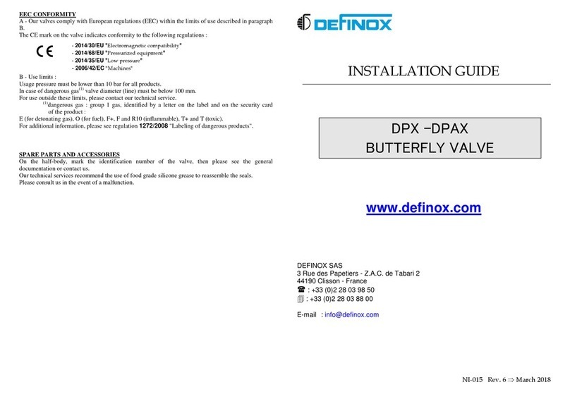
EEC CONFORMITY
A - Our valves comply with European regulations (EEC) within the limits of use described in paragraph
B.
The CE mark on the valve indicates conformity to the following regulations :
B - Use limits :
Usage pressure must be lower than 10 bar for all products.
In case of dangerous gas(1) valve diameter (line) must be below 100 mm.
For use outside these limits, please contact our technical service.
(1) dangerous gas : group 1 gas, identified by a letter on the label and on the security card of the
product :
E (for detonating gas), O (for fuel), F+, F and R10 (inflammable), T+ and T (toxic).
For additional information, please see regulation 67/548/EC "Labeling of dangerous products".
10
-
SPARE PARTS AND ACTUATOR DISASSEMBLY
Note the index number on the valve and refer to the general documentation or contact us. Please contact
us in the event of a malfunction.
Actuator disassembly is a simple but delicate operation requiring the use of the appropriate tools and
reference to the valve disassembly instructions.
Please contact us for these instructions or to request maintenance operations at our premises or on site.
N.B.: The valve must be out of service prior to any intervention and disassembly of the components
with the pretensioned spring must be performed in accordance with the instructions on the maintenance
information sheet.
INSTALLATION GUIDE
CONTROL VALVE
www.definox.com
DEFINOX SAS
3 Rue des Papetiers - Z.A.C. de Tabari 2
44190 Clisson - France

: +33 (0)2 28 03 98 50

: +33 (0)2 28 03 88 00
E-mail: info@definox.com
- 89/336 Electromagnetic compatibility
- 97/23 Pressurized equipment
- 73/23 Low pressure
NI-029 Rev. 7 ⇒ September 2016
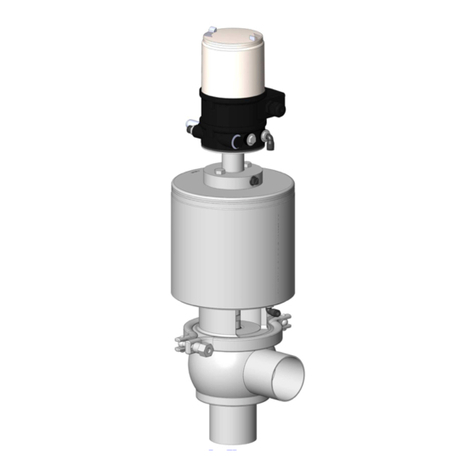
DCX3 CONTROL VALVE
1 – DCX3 valve body
2 – Piston
3 – Seal
4 – Seal support plate
5 – Actuator cylinder
6 – Positioner Burkert 8693
7 – Collar clamp
8 – Seal
9 – Ring (Qty 2)
10 – Seal
1
.
D
ESCRIPTION OF THE CONTROL VALVE
:
DEFINOX control valves with position memory are ideal for the control and regulation of flow rates,
temperatures, levels, pressure and for use in biotechnology. DEFINOX control valves are currently
available in sizes DN 25 to DN 104 in standard food grade and aseptic versions. These valves have a
simple loop function.
2 . The PID controller (Proportional - Integral - Derived)
The controller processes the control discrepancy. This calculator compares the set point value with the
actual value and supplies an output signal depending on this difference (processes the 4-20 mA output).
Two types of control are possible:
- Manual control according to system evaluation (valve and service conditions)
- In auto-adaptive mode, the P.I.D. controller calculator automatically performs some of the
control functions
3 . The valve
The valve can operate in NO or NC with an optional metal/metal seal. The profiled disc facilitates
linearization of valve operation.
Putting DEFINOX valve into service
Refer to the attached notice Bürkert:
Follow the fitting and operating instructions carefully. Take account of the actual working conditions
and observe the technical specifications for the valve.
1
-
VALVE
IDENTIFICATION
DEFINOX control valves have an identification number. You will need this number in order to identify
the spare parts you may request.
2
-SERVICE CONDITIONS
The working conditions of this valve (pressure, temperature, fluid transported, etc.) must comply with
the general technical specifications described in the DEFINOX catalogue available on request.
3
-AIR SUPPLY CONDITIONS
The actuator is supplied with dry, filtered air at a pressure of 4.5 to 8 bar. The actuator air couplings are
designed for a 4/6 diameter hose fitting. The valve has a max. working pressure of 6 bar, a max.
temperature of 140°C and an acceptable vacuum of 0.4 bar.
4
-SEALS
Unless otherwise specified in the order, DCX3 control valves are equipped with the
following seals :
• EPDM or FKM for the O-rings
Choosing the right type of seal is critical to correct valve operation. This is not always easy,
as all characteristics of the fluids circulating through the valve must be taken into
consideration. We can help you make this choice. Ensure that the grease used is compatible
with the elastomer seals, particularly EPDM.
5
-N.C. –, N.O. – AND D.A. CONFIGURATION
DCX3 control valves are supplied as standard in an N.C. configuration and require an air
supply to remove the piston.
The valves can be supplied in an N.O. or D.A. configuration on request.
Important : Before changing the configuration, consult the maintenance instructions (IT.DFX.036).
6
-PRECAUTIONS TO BE TAKEN WHEN CARRYING OUT WELDING OF THE BODIES
Adjust the pipes : check the straightness, the out-of-roundness and the offset (play<0.5 mm),
to limit the restrictions created by welding.
Any modification to the valve body for the purpose of welding must be carried out with the
agreement of Definox.
Support the pipes at least 10D from the valve (valve nominal diameter).
7
-INSTALLING THE VALVE ON THE PROCESS LINE
To install the valve on the process line, the weld-on body must be separated from the rest of the valve
to prevent seal damage.
To carry out this simple operation, proceed as follows while referring to the diagrams :
A- DCX3 (single-body valve)
Put the valve in the open position. With an N.C. configuration, the actuator ( 5 ) must be supplied with
air.
Remove the clamp ( 7 ) . Shut off the air and separate the body ( 1 ) from the rest of the valve. Weld the
body to the pipes.
Important : For subsequent actuator and piston disassembly, you will need to be able to remove one of
the bodies (preferably the top one) from the line. Make sure this body is welded to a removable section
or between fittings.
5
4
3
2
1
8
8
7
Lower channel
Top connection(s)
9
10
6

Other manuals for DCX3

5

Other Definox Control Unit manuals

Definox VDCI-MC-FC Operation and maintenance manual

Definox

Definox VDCI-MC-FC Operation and maintenance manual

Definox VEOX SP 3 BODY Operation and maintenance manual

Definox

Definox VEOX SP 3 BODY Operation and maintenance manual

Definox VEOX PMO Operation and maintenance manual

Definox

Definox VEOX PMO Operation and maintenance manual

Definox DCX3 Operation and maintenance manual

Definox

Definox DCX3 Operation and maintenance manual

Definox ICS Operation and maintenance manual

Definox

Definox ICS Operation and maintenance manual

Definox VDCI-MC PFA User manual

Definox

Definox VDCI-MC PFA User manual

Definox DCX3 User manual

Definox

Definox DCX3 User manual

Definox DPAX User manual

Definox

Definox DPAX User manual

Definox Sorio Operation and maintenance manual

Definox

Definox Sorio Operation and maintenance manual

Definox DCX4 HP User manual

Definox

Definox DCX4 HP User manual

Definox DCX3 Operation and maintenance manual

Definox

Definox DCX3 Operation and maintenance manual

Definox DPX1EBC Operation and maintenance manual

Definox

Definox DPX1EBC Operation and maintenance manual

Definox DCX3 User manual

Definox

Definox DCX3 User manual

Definox DCX3 Operation and maintenance manual

Definox

Definox DCX3 Operation and maintenance manual

Definox DPX EBC User manual

Definox

Definox DPX EBC User manual

Definox Sorio Basic 1EV User manual

Definox

Definox Sorio Basic 1EV User manual

Definox Sorio Basic 3EV User manual

Definox

Definox Sorio Basic 3EV User manual

Definox DPAX GEN 2 User manual

Definox

Definox DPAX GEN 2 User manual

Popular Control Unit manuals by other brands

Flowserve NAF ProCap User instruction

Flowserve

Flowserve NAF ProCap User instruction

Burkert 2060 quick start

Burkert

Burkert 2060 quick start

DINA DNSL-ZM Original instruction manual

DINA

DINA DNSL-ZM Original instruction manual

LumiGrow smartPAR installation guide

LumiGrow

LumiGrow smartPAR installation guide

Iluminarc Ilumicode V 2.21 user manual

Iluminarc

Iluminarc Ilumicode V 2.21 user manual

IDS X Series Installer manual

IDS

IDS X Series Installer manual

Tews Technologies TIP866-TM-20 user manual

Tews Technologies

Tews Technologies TIP866-TM-20 user manual

NEC NEAX 2400 ICS manual

NEC

NEC NEAX 2400 ICS manual

Vimar by-me Eikon 20520 quick start guide

Vimar

Vimar by-me Eikon 20520 quick start guide

E+E Elektronik EE1900 user manual

E+E Elektronik

E+E Elektronik EE1900 user manual

ICP DAS USA M-7067D quick start guide

ICP DAS USA

ICP DAS USA M-7067D quick start guide

GEM 638 Installation, operating and maintenance instructions

GEM

GEM 638 Installation, operating and maintenance instructions

Burkert 8690 operating instructions

Burkert

Burkert 8690 operating instructions

Edwards GSA-CC1 Installation sheet

Edwards

Edwards GSA-CC1 Installation sheet

Bartec POLARIS SMART HMI 17-71V6-1 Series user manual

Bartec

Bartec POLARIS SMART HMI 17-71V6-1 Series user manual

Elk Products ELK-110 quick start guide

Elk Products

Elk Products ELK-110 quick start guide

Warren rupp Sandpiper HD20F Service & operating manual

Warren rupp

Warren rupp Sandpiper HD20F Service & operating manual

SMA 1C4-313-001-001 Replacement manual

SMA

SMA 1C4-313-001-001 Replacement manual

manuals.online logo
manuals.online logoBrands
  • About & Mission
  • Contact us
  • Privacy Policy
  • Terms and Conditions

Copyright 2025 Manuals.Online. All Rights Reserved.