Cinergia B2C10 User manual
Electronic Load (EL DC)
Installation and operation manual
Tel: +49(0)7842-99722-00
Fax: +49(0)7842-99722-29
www.caltest.de
Kohlmattstrasse 7
D-77876 KAPPELRODECK
Caltest Instruments GmbH

2/ 56
INDEX
1. INTRODUCTION ..................................................................................................................... 5
1.1. Symbols used................................................................................................................. 5
1.2. Safety notes................................................................................................................... 5
1.3. Quality and regulations................................................................................................. 5
2. PRESENTATION...................................................................................................................... 7
2.1. Introduction .................................................................................................................. 7
2.2. Converter features ........................................................................................................ 8
2.3. Operation and connection modes ................................................................................ 9
2.4. Configuration and control of the converter.................................................................. 9
2.5. Functional diagram........................................................................................................ 9
2.6. Principle of operation.................................................................................................. 10
3. INSTALLATION ..................................................................................................................... 16
3.1. Important safety instructions...................................................................................... 16
3.2. Equipment views......................................................................................................... 16
3.3. Equipment reception................................................................................................... 20
3.3.1. Unpacking and checking the content.................................................................. 20
3.3.2. Storage ................................................................................................................ 20
3.3.3. Transport to location........................................................................................... 21
3.3.4. Location............................................................................................................... 21
3.4. Connection .................................................................................................................. 23
3.4.1. Earth protection .................................................................................................. 23
3.4.2. Input connection, terminals (X1 to X5). .............................................................. 23
3.4.3. Output connection, terminals (X6 to X10) .......................................................... 23
3.4.3.1. DC unipolar mode............................................................................................ 23
3.4.3.2. DC bipolar mode.............................................................................................. 23
3.4.4. External Emergency Power Off connection (X12)............................................... 23
3.4.5. Output signal of local Emergency Stop pushbutton (OPTIONAL) ....................... 25
3.4.6. Communications (Optional) ................................................................................ 26
3.4.7. Digital inputs and outputs................................................................................... 26
3.4.8. Analog inputs and outputs (AIO Optional).......................................................... 27
4. OPERATION ......................................................................................................................... 28
4.1. Safety........................................................................................................................... 28
4.2. State Machine ............................................................................................................. 28

EL DC Instalation and operation manual v13.docx
3/ 56
4.2.1. Initialization......................................................................................................... 29
4.2.2. Standby................................................................................................................ 29
4.2.3. Precharge ............................................................................................................ 30
4.2.4. Ready................................................................................................................... 30
4.2.5. Run ...................................................................................................................... 30
4.2.6. Alarm ................................................................................................................... 30
4.3. Operation modes ........................................................................................................ 31
4.3.1. Constant Impedance (CI)..................................................................................... 31
4.3.2. Constant Current (CC) ......................................................................................... 31
4.3.3. Constant Power (CP) ........................................................................................... 32
4.3.4. Constant Voltage (CV) ......................................................................................... 32
4.4. Connection modes ...................................................................................................... 32
4.5. Working with the equipment...................................................................................... 33
4.5.1. Start-up................................................................................................................ 34
4.5.2. Stop ..................................................................................................................... 34
4.5.2.1. Full stop........................................................................................................... 34
4.5.2.2. Standby stop.................................................................................................... 35
4.5.2.3. Ready............................................................................................................... 35
4.5.3. Emergency stop................................................................................................... 35
4.5.4. Accidental shut down.......................................................................................... 36
4.5.5. Alarms.................................................................................................................. 36
4.5.6. Alarms reset ........................................................................................................ 37
5. LOCAL TOUCHSCREEN CONTROL PANEL............................................................................. 38
5.1. Basic functions............................................................................................................. 38
5.2. Menus and submenus................................................................................................. 38
5.2.1. General................................................................................................................ 38
5.2.2. Operational ......................................................................................................... 39
5.2.3. Supervision.......................................................................................................... 42
5.2.4. Configuration....................................................................................................... 42
5.2.5. Alarms.................................................................................................................. 43
5.2.6. About EL .............................................................................................................. 44
6. REMOTE COMMUNICATIONS.............................................................................................. 44
6.1. IQ MANAGEMENT ....................................................................................................... 47
7. HUMAN MACHINE INTERFACE............................................................................................ 49

4/ 56
7.1. Operation .................................................................................................................... 49
7.1. Alarm........................................................................................................................... 50
7.2. Supervision.................................................................................................................. 51
7.3. Unipolar/Bipolar connection....................................................................................... 52
7.4. DC sequence................................................................................................................ 53
8. WARRANTY AND MAINTENANCE........................................................................................ 55
8.1. Replacing the input fuses............................................................................................ 55
8.2. Fans ............................................................................................................................. 55
8.3. DC bus capacitors........................................................................................................ 55
8.4. Warranty ..................................................................................................................... 55
8.5. Claim procedure.......................................................................................................... 56
EL DC Instalation and operation manual v13.docx
5/ 56
1. INTRODUCTION
Dear customer, on behalf of CINERGIA team, thank you for the confidence placed in our
company and for the purchase of this product. Please, read carefully this manual before using
the equipment to get familiarized with it and to obtain the maximum performance from it.
This document is intended for appropriately qualified personnel. Only personnel with the
appropriate skills are allowed to perform the electrical connection and commissioning of the
equipment.
The information in this documentation is not binding. CINERGIA reserves the right to make
changes in part or in the whole at any time and without prior notice due to technical advance or
product improvement.
1.1. Symbols used
DANGER: Indicates a hazardous situation which can result in death or serious
injury and can cause important damage or destruction of the equipment or the
property.
WARNING: Indicates important information that must be taken into account to
operate the equipment. Take the appropriate prevention measures.
INFORMATION: Information that is important but is not safety-relevant.
1.2. Safety notes
Improper use of this equipment can cause both important personal injury and physical damage
to the electrical power grid and the loads connected to it. Read this document carefully and
follow all safety precautions at all times.
1.3. Quality and regulations
The equipment is based on a hardware designed, manufactured and commercialized in
accordance with the standard EN ISO 9001 of Quality Management Systems. The marking shows
conformity to the EEC Directive by means of application of the following standards:
• 2006/95/EC Low voltage directive.
• 2004/108/EC Electromagnetic Compatibility directive (EMC)
In accordance with the specifications of the harmonized standards:

EL DC Instalation and operation manual v13.docx
6/ 56
• EN-IEC 62040-1. Uninterruptible power supply (UPS). Part 1-1: General and safety
requirements for UPS’s used in accessible areas by end users.
• EN-IEC 60950-1. IT equipments. Safety. Part 1: General requirements.
• EN-IEC 62040-2. Uninterruptible power supply (UPS). Part 2: Prescriptions for Electromagnetic
compatibility (EMC).
• EN-IEC 62040-3. Uninterruptible power supply (UPS). Part 3: Methods of operation
specification and test requirements.
The manufacturer responsibility is excluded in the event of any modification or intervention in
the product by the customer’s side.

EL DC Instalation and operation manual v13.docx
7/ 56
2. PRESENTATION
2.1. Introduction
As an electronic load, the EL is designed to test electric and electronic equipment in linear and
non-linear DC loading. It allows to verify the functionality of the Equipment Under Test (EUT) in
normal and fault operation.
The main functionalities of the EL are the following:
-It converts the AC input, of the main grid, in a controlled DC output by using an IGBT-
based switching topology and DSP-based state-of-the-art digital control.
-It can be operated as:
oCI: Constant Impedance output
oCC: Constant Current output
oCP: Constant Power output
oCV: Constant Voltage output
-As a bidirectional converter, energy can flow from the grid to the EUT or viceversa. It
allows energy saving during the tests by returning energy to the power grid.
-The AC current consumed from the grid is sinusoidal (THD < 6%).
-The user can define the reactive power to be injected by the EL and also choose between
capacitive or inductive.
The power range covered by the EL electronic loads goes from 6.75 to 160kW. The parallelization
of ELs is also possible to increase power:
REFERENCE
RATED POWER (25ºC)
RATED CURRENT (25ºC)
WEIGHT
DIMENSIONS
kVA
kW
Independent
Parallel
Bipolar
kg
DxWxH (mm)
0-750V
0-750V
-350 to
350V
B2C7.5
7.5
6.75
±10A
±30A
±10A
150
770x450x1100
B2C10
10
9
±15A
±45A
±15A
150
B2C15
15
13.5
±20A
±60A
±20A
150
B2C20
20
18
±25A
±75A
±25A
150
B2C30
30
27
±30A
±90A
±30A
150
B2C40
40
36
±38A
±115A
±38A
185
B2C50
50
45
±47A
±140A
±47A
185
B2C60
60
54
±57A
±180A
±57A
185
B2C80
80
72
±105A
±315A
±105A
265
880x590x1320
B2C100
100
90
±130A
±390A
±130A
290
B2C120
120
108
±130A
±390A
±130A
290
B2C160
160
128
±155A
±465A
±155A
540
850x900x2000
B2C200
200
160
±185A
±555A
±185A
550

EL DC Instalation and operation manual v13.docx
8/ 56
2.2. Converter features
MAGNITUDE
VALUE
Power
7.5kVA-200kVA
Input side (GRID side)
AC Voltage
Rated
3x400Vrms+Neutral+Earth
Voltage range
+15% / -20%
Rated AC Current
Depends on model (see table)
10-290Arms per phase
Frequency
48-62Hz
THDi
(at rated power)
<3%
Power Factor
Typical at rated power
≥0.99
Configurable by user
0-1 (capacitive/inductive)
Efficiency
(at rated power)
>92%
Overload
125% for 10 min /150% for 60 s
Output side (EUT side)
DC Voltage
Channel-Com_neg
Channel_Com_neg
Channel_com_neg
20 to 750V (≤60kVA)
40 to 750V (>60kVA)
-350 to 350V
Minimum voltage
At rated power
320V
DC Current
Parallel channels mode
Independent channels mode
Bipolar output
0 to ±555A global
0 to ±185A per channel
0 to ±185A per channel
DC Overcurrent
110% during 1min
Modes of operation
Range
Resolution
Ripple
Constant Current
0-±100%
<±0.1%
<1%
Constant Power
0-±100%
<±0.1%
<1%
Constant Resistance
min.-100%
<±0.1%
<1%
Constant Voltage
0-100%
<±0.1%
<1%
Response time
Rated resistance load
1-5ms (10-90%)
General
Measurements
Input Voltage (Vrms) and current (Irms)
Input and Output Power
Output voltage (Vrms) and current (Irms)
Temperatures
User interface
3.2’’ Touchscreen
Local Control port: 4 digital inputs, 3 relay outputs (Option for AIO)
Communication Port: Ethernet (Optionals: RS485, RS232, CAN)
Communication Protocol: Modbus/TCP
Humidity
10-90% (Absolute maximum, without condensation)
Temperature
5-35ºC (Absolute maximum)
Cooling
Forced air
Protections
Over Current, Over Voltage, Shortcircuit, Overtemperature
Standards
CE Marking
Safety
EN-62040-1-2,EN-60950-1
EMC
EMC: EN-62040-2
Please note that items marked as optional shall be requested specifically at additional cost.

EL DC Instalation and operation manual v13.docx
9/ 56
2.3. Operation and connection modes
The output of the power converter is formed by three phases referenced to the neutral point of
the system (N). Consequently, the user can choose between two possible connection modes for
the electronic load:
-Independent phases: each phase (U, V, W) is controlled independently. The current
setpoint can be different in angle and magnitude for each of the three phases.
-Parallel phases: It is exactly the same as the previous case, but in this case the user has
shorted the phases. In this case the total amount of current consumed will be the sum
of all three phases.
-Unipolar mode: Electronic Load behaves as 3 independent and positive DC power
supplies.
-Bipolar mode: Electronic Load behaves as 2 independent DC power supplies. One is
positive and the other negative.
Three operation modes are allowed:
-Constant Impedance (CI): the output impedance is controlled to the set point value. The
emulator will perform as a constant R.
-Constant Current (CC): the output current is controlled to the set point value.
-Constant Power (CP): the output active power is regulated to the set point value.
-Constant Voltage (CV): the output voltage is controlled to the set point value.
2.4. Configuration and control of the converter
The converter can be interfaced by three means:
-Local touchscreen: a 3.2” color local touchscreen panel can be used to configure,
monitor and operate the electronic load. See section Local Touchscreen Control Panel
for further information.
-Analog and digital inputs: the converter owns three isolated analog inputs (+/-10V) and
tow optocoupled digital inputs.
-Remote interface: an Ethernet communication interface with protocol MODBUS/TCP
can be used to configure, monitor and operate the electronic load. By using HMI
software application provided by CINERGIA, uploading of excel files is also possible.
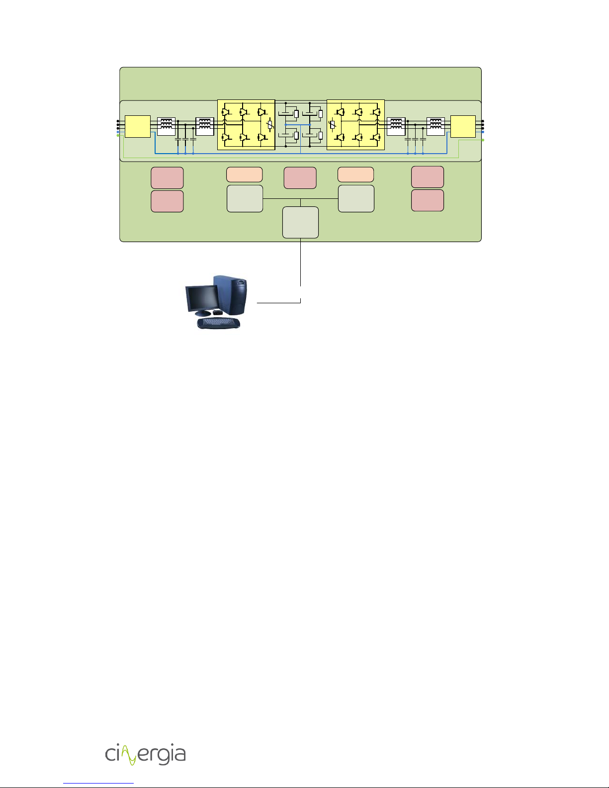
2.5. Functional diagram
The diagram below is the conceptual function block diagram of the converter:
AC
ACTIVE RECTIFIER
GRID
DC AC
DC
EUT
DC/AC
Input LCL
filter
Input EMI
filter
Protections Protections
Output EMI
filter
Output LCL
filter
OPTIONAL
ELECTRONIC LOAD

EL DC Instalation and operation manual v13.docx
10 / 56
The main components of the diagram are the following (from grid side to EUT side):
-Isolation transformer: a 50/60Hz isolation transformer can be provided optionally in
order to isolate the output phases. In this case, an isolation monitor can be integrated
in the converter to detect isolation faults also.
-Input protections: these protections include a thermal-magnetic circuit breaker and
fuses. The connection of the converter input with the grid is done by screw terminals.
Please follow the safety instructions in the Installation section to connect the electronic
load.
-Input EMI filter: an electromagnetic filter is integrated to fulfil electromagnetic
compatibility regulations. The structure of the filter is the same as the one of the output
EMI filter.
-Input LCL filter: the purpose of this filter is to reduce the current distortion at
frequencies equal to or higher than switching frequency and reduce THD.
-Active Rectifier: a three-branch IGBT active front end is integrated in the equipment to
consume/inject a sinusoidal current from/into the grid.
The DC link voltage is set to 800V providing a regulation margin for fast transients at the
output of the electronic load.
The active rectifier has bidirectional power flow capability and the injected reactive
power (grid side) can be defined by the customer.
-DC/AC output converter: it is a three-branch IGBT converter. Its topology is the three
phase inverter and allows the conversion from the DC bus to each of the output AC
phases.
The user can choose between having each phase controlled independently or having the
three of them controlled as a unique phase (sharing the same operation mode and
setpoints).
-Output LCL filter: analogously to the input LCL filter, the filter reduces the current
distortion (caused by switching) at the output of the electronic load.
-Output EMI filter: a high frequency common mode LC filter is used to reduce the
electromagnetic disturbances at the output of the electronic load.
-Output protections: a disconnector is provided to isolate the output from the EUT. Screw
terminals are also integrated to connect the EUT. Please, follow safety instructions in
Installation section to connect them.
2.6. Principle of operation
Below, a technical diagram of the converter is shown:
EL DC Instalation and operation manual v13.docx
11 / 56
Drivers x6 Drivers x6
Current
sensor x3
Voltage
sensor x2
Voltage
sensor x3
Current
sensor x3
Voltage
sensor x3
PE
-U
-U
PE
PE
EMC
filter
EMC
filter
AC output
PE
EL
U
DSP
board
DSP
board
CAN/
Ethernet
board
CAN
MODBUS/TCP
ETHERNET
V
W
N
PE
R
S
T
N
PE
(Please note that earth protection cable is only connected to the cabinet chassis).
State-of-the-art digital control is used in all CINERGIA products. In the EL case, the control system
algorithms are computed in two DSP based hardware, designed by CINERGIA, allowing a
multitask execution of the regulation systems for the Active Rectifier and the Inverter output.
This produces a fast transient response and a high performance against EUT changes. A 12 bits
analog to digital conversion, with digital processing, allows a high resolution output up to 0.1%.
Resonant control (only AC)
Control algorithms based on Resonant controllers are used in both AC sides; i.e. Resonant
Control is always used in grid side but it is used in EUT side only when AC output option is chosen
for the electronic load.
The algorithms regulation is structured in blocks resonating at a given frequency. Within the
resonant frequency each block allows the suppression of gain and phase errors of the current.
Thanks to this, each harmonic can be controlled independently and thus it can be generated or
suppressed, as needed.
The following diagram illustrates how the mentioned algorithms operate:

EL DC Instalation and operation manual v13.docx
12 / 56
PR ω0 PWM x3
Σ
PR ω1
PR ω2
PR ω3
...
Feedback
+
-
KR
KFF
Setpoint
generator
Therefore, the main characteristics of the Resonant Control applied are the ones listed below:
-Control loop rate of 15 kHz.
-15 harmonics controlled*: 1st-15th
-15 control loops executed per phase.
-45 control loops executed in total (for the 3 phases).
-Each control loop controls independently magnitude and angle of one harmonic.
-Any kind of load can be implemented in the EUT side.
-All harmonics can be suppressed in the grid side.
* It should be noted that the equipment bandwidth is 800 Hz. Therefore, the harmonic content
will be determined by the bandwidth as well as by the fundamental frequency specified by the
user.
Finally, the following pictures are some examples of how the EL Resonant Control can work. It is
important to take into account that, in these three pictures:
-Yellow waveform: input Uphase-N
-Green waveform: input Iphase-N
-Pink waveform: output Uphase-N
-Blue waveform: output Iphase-N

EL DC Instalation and operation manual v13.docx
13 / 56
In this case, there is reactive power consumption from the EUT (PF = 0) and no power is injected
into the grid.
In this second picture, the EL is behaving like a single-phase rectifier.

EL DC Instalation and operation manual v13.docx
14 / 56
In this last case, the EL is behaving like a three-phase rectifier.
PID control
The EUT side control algorithm is based on a traditional current PID controller. In case controlling
power, or even the impedance, both magnitudes are decoupled and translated to current set
points on each control loop.
The following diagram illustrates how the algorithms operate:
Both in voltage mode and current mode, the equipment is regulated for the limits imposed by
the interface: maxIout, minIout, maxVout and minVout. In case that those limits are not
configured, the equipment is protected by the natural limits (110% of the nominal current).
The following table explains how those limits work.

EL DC Instalation and operation manual v13.docx
15 / 56
Parameter
Description
Default
maxIout
Maximum limitation of positive output current:
maximum current the equipment is able to inject
Maximum current
limitation
110% Irated
minIout
Maximum limitation of negative output current:
maximum current the equipment is able to drain
Maximum current
limitation
110% Irated
maxVout
Maximum limitation of voltage the equipment is
able to put in the output
750V
Range: 0V-750V
minVout
Minimum limitation of voltage the equipment is able
to put in the output
30V
Range: 0V-750V
EL DC Instalation and operation manual v13.docx
16 / 56
3. INSTALLATION
3.1. Important safety instructions
As a device with class l protection against electric shocks, it is essential to install a protective
earth wire (connect earth ). Connect the protection earth wire to the terminal (X5) before
connecting the grid to the electronic load input.
All the electrical connections, including those for control (interface, remote control…etc.), shall
be done with all the switches in OFF position and with the mains supply disconnected (thermal-
magnetic circuit breaker in OFF position too).
It must never be forgotten that the EL is a power converter, so users must take all
necessary precautions against direct or indirect contact.
Warning labels should be placed on all primary power switches installed in places far from the
device to alert the electrical maintenance personnel of the presence of a voltage in the circuit
up to 10 minutes after stopping the device.
In devices without isolation transformer, precautions must be taken as they are not
isolated from the alternating input line, and there might be dangerous voltage
between the output phases and the ground.
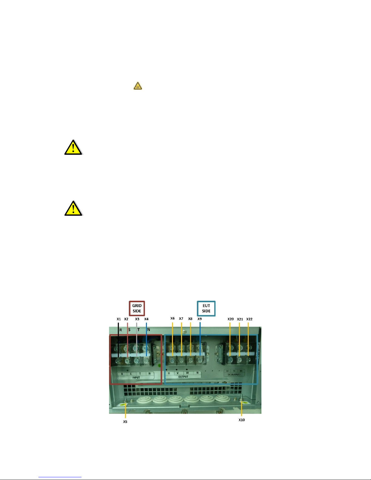
3.2. Equipment views
Electrical connections:

EL DC Instalation and operation manual v13.docx
17 / 56
Local front panel:
Front view (with the door open):
LCD
EPO
EL DC Instalation and operation manual v13.docx
18 / 56
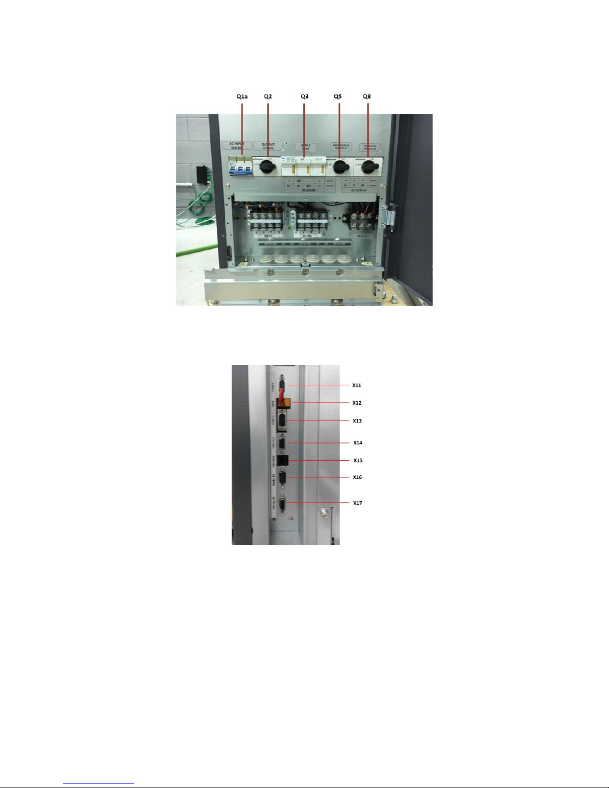
Detailed view of the front protections and switches:
Detailed view of the signal connectors:

EL DC Instalation and operation manual v13.docx
19 / 56
General view (with the front door closed):
Protection elements (Q*):
(Q1a) Input thermal-magnetic circuit breaker or disconnector according to power of
the equipment
(Q2) Output disconnector
(Q3) Output fuses
(Q5) Parallel connection switch
(Q7) Isolation detector (which is inside the cabinet and it is optional)
(Q8) Bipolar/unipolar switch
Connection elements (X*):
(X1) Phase input terminal R.
(X2) Phase input terminal S.
(X3) Phase input terminal T.
(X4) Neutral input terminal N.
(X5) Earth connection terminal for main supply input ( ).
(X6) Phase output terminal U.
(X7) Phase output terminal V.

EL DC Instalation and operation manual v13.docx
20 / 56
(X8) Phase output terminal W.
(X9) Neutral output terminal N.
(X20) Negative output terminal U.
(X21) Negative output terminal V.
(X22) Negative output terminal W.
(X10) Earth connection terminal for EUT ( ).
(X11) DB9 connector for RS485 communications.
(X12) Terminals for external Emergency Power Off (EPO) button.
(X13) DB9 connector for CAN communications (input).
(X14) DB9 connector for CAN communications (output).
(X15) RJ45 connector for MODBUS interface.
(X16) DE15 connector for digital inputs and outputs.
(X17) DE15 connector for analogic inputs and outputs.
3.3. Equipment reception
3.3.1. Unpacking and checking the content
On receiving the device, make sure that the converter has not suffered any damage during the
transportation. Otherwise, make all pertinent claims to the supplier or to CINERGIA.
The packing of the device consists of a wooden palette, a cardboard or wooden packaging
(depending on the case), expanded polystyrene corner pieces, a polyethylene sleeve and bands;
all recyclable materials. Therefore, they should be disposed of according to current regulations.
We recommend to keep the packaging in case its use is necessary in the future.
In order to unpack, cut the bands and remove the cardboard packaging with a vertical
movement. In case of wooden packaging, remove it with the appropriate tools. Afterwards,
remove the corner pieces and the plastic sleeve. At this point the equipment will be unpacked
on the pallet. Please, use suitable tools to lower the converter from the pallet.
After unpacking the equipment, check that the data in the nameplate (stuck on the inner part
of the front door) correspond to those specified in the purchase order. Contact the supplier or
CINERGIA in case of disconformity.
Keep the equipment in the original package if it will not be used in order to protect it from any
possible mechanical damages, dust, dirt, etc…
3.3.2. Storage
The equipment shall be stored in a dry, ventilated place and protected against rain, water jets
or chemical agents. It is advisable to keep the converter into its original package, which has been
designed to assure the maximum protection during the transport and storage.
Do not store the unit where the ambient temperature exceeds 40ºC or falls
below -20ºC
This manual suits for next models
25
Table of contents
Popular Batteries Charger manuals by other brands

Sterling Power
Sterling Power Pro Batt Ultra BB1260 user manual

TCE
TCE NEOS Series instruction manual

Chargery
Chargery 320B operating instructions

LXE
LXE HX1A376 user guide

Associated Equipment
Associated Equipment Heavy Load Electronic Battery Tester 6033 Operator's manual

GNB
GNB Tubular LMX Installation and operating instructions


ABL
ABL eMH3 installation manual

Circontrol
Circontrol Rapid Series Installation & user manual

EXTOL PREMIUM
EXTOL PREMIUM 8891894 Translation of the original user manual

Goobay
Goobay 54334 quick start guide

Helvi
Helvi DIGICAR 600 Operating instructions manual

Nordelettronica
Nordelettronica NE284 instruction manual