Sterling Power Pro Batt Ultra BB1260 User manual
Sterling Power Products
Copyright
STERLI G
POWER
Pro Batt Ultra - Battery to Battery Charger
Copyright © 2017
Sterling Power
V60 July 2017
Starter
Engine Bat.
Pos
in Pos
out
Neg
fuse fuse
House / Domestic / Aux
/ Bow thruster
Main Power
Terminals
MUST READ
For the vast majority of users (90%+) reading this paragraph should
be sufficient for installation. The unit can be installed by simply
connecting it between an input and output battery as depicted. The
unit, by default, shall start charging when the input voltage exceeds
13.2V and switches off when the voltage drops below 13.0V for more
than 240s (adjustable). Going above 13.2V for 5 seconds shall reset
this timer . The default charging profile is 14.4V abs. and 13.6V float -
for sealed lead acid batteries (x2 for 24V | x3 for 36V | x4 for 48V). This
means that the vast amount of installations can be fitted out of the box
without any adjustments.
There is also an ignition feed option - Unit on when ignition is on, unit off
when ignition is off. Please read the manual for additional information.
Code:
BB1230
12V-12V 30A input
BB122440
12V-24V 40A input
battery temp
sensor
USERS MANUAL.
Sterling Power Products
H Charge Float
In / Unit Out / Rem
Batt.
V12.2
Temp
Menu
Change
Volts
Select
Audible alarm on/off
hold > 3 sec
On / Off
hold>3 sec
Fault
Absorption
Cond.
Optional Remote
Instructions inside
technology
4
D
U
:
L
R
A
A
T
I
B
G
L
I
E
D
:
:
D
C
I
E
S
M
I
A
G
N
N
Y
D
ProDigital
RoHS
compliant R.B.F
Regenerative
raking riendly B F
Test Report Sheet
Each product gets uniquely tested and a report is generated.
This unique test report is present inside this box.
You must keep this test sheet in this box and keep this box safe.
This sheet should be present when the charger is being warranted.
For other European languages refer to website:
Europe / RoW: www.sterling-power.com
North America: www.sterling-power.usa.com
*default mode does not require ignition feed*
Code:
BB1260 12V-12V 60A input
BB122470 12V-24V 70A input
BB123670 12V-36V 70A input
BB124870 12V-48V 70A input
BB242435 24V-24V 35A input
BB241235 24V-12V 35A input
BB123670 12V-36V 70A input
BB124870 12V-48V 70A input
++
+
Please read the legal and safety
information first before proceeding
and we strongly advise hiring a
professional to fit.
STERLI G
POWER
Important
upgrades
and features
Due to the fast and fluid changes being
made in the vehicle industry with the euro 6
+ variants between vehicle manufacturers,
Sterling power is constantly upgrading the
software in the products to keep up with
changes, unfortunately the printed
installation instructions simply don't keep
pace with the changes. The latest installation
instructions can be downloaded from the
internet.
To download the latest instructions, to
access the above features simply go to:
German, second half of this manual
These instructions are constantly
being modified and updated. The
Sterling website is worth referring to
for the latest instruction download.

Sterling Power Products
Copyright
STERLI G
POWER
Contents Page
Product Specifications
BB1230 BB1260 BB122470 BB123670 BB124870 BB241235 BB242435
Input Voltage (V DC) 11 - 20 11 - 20 11 - 20 11 - 20 11 - 20 22 - 40 22 - 40
Input Current (A) 30 60 70 70 70 35 35
Battery types (all models)
IP rating IP21 IP21 IP21 IP21 IP21 IP21 IP21
Ignition Protected Yes Yes Yes Yes Yes Yes Yes
Quiescent Current (mA) 1 1 1 1 1 1 1
Battery Connector WJ116VW WJ116VW WJ116VW WJ116VW
Weight (Kg) 1.2 1.4 1.4 1.4 1.4 1.4 1.4
Dimensions (LxWxD) mm 190 x 160 x 50
AGM (2) | GEL (2) | SEALED | OPEN | LiFePO4 | CALCIUM | CUSTOM
8mm input | WJ116VW output
190 x 160 x 70
Seite 16 Deutsch
Page 16 for German
2
Legal and Safety Information Page 3 Force Options - Device options Page 10
How to use the instructions Factory Reset
Copyright and Plagiarism Force operation w ithout output voltage
Maintenance and Repair Force Float mode
Safety and Precautions Force Unit on / off
Display annotations Page 4 - 5 Force Unit to half pow er mode
Front Label display annotated Sleep timer / Off timer adjust.
Under the lid annotation Custom Battery Profile Selection Pages 11 - 12
Recommended cable and fuse sizes Customise Boost / Absorption voltage
Quick Installation guide Page 6 Customise Conditioning voltage
Basic w iring diagram Customise Float voltage
Basic operational modes 1 | 2 | 3 Customise Absorption time factor
Guide to Buttons Page 7 Customise minimum and maximum absorption times
Detailed Installation guide Page 8 Customise Operational Voltages
Operational modes 1 | 2 | 3 Remote Control Operations Page 13
Installation diagram Comprehensive breakdow n of remote functions
Choosing the correct operational mode Fault Finding | Troubleshooting Page 14
Wiring the correct operational mode Fundamental fault + troubleshootings
First Turning the unit on Page 9 LED displays w / meanings and solutions
Changing the Battery Chemistry Profile Sterling's Warranty Statement Page 15
Battery Chemistry voltage values table Customer service and w arranty declaration
Front panel meter readings / meanings

Sterling Power Products
Copyright
4
2
Using the Instruction Manual
This manual must be read throughout before installing
this electronic device. Do not lose these instructions -
keep them safe. The most up to date instructions can
be found on the Sterling Power website. Please refer to
the latest instruction manual before contacting Sterling.
At Sterling, we endeavour to include all of the product
information that we can think of into the manual.
Installation of the electronic device must be carried out
by a qualified and trained personnel only. The
personnel must be familiar with the locally accepted
guidelines and safety measures.
Sterling Power’s warranty statement
A comprehensive warranty statement is provide at the
back of the instruction manual. A comprehensive
warranty statement can also be found on sterling-
power.com.
Copyright and plagiarism
Copyright © 2015 Sterling Power. All rights reserved.
Reproduction, transfer, distribution or storage of part or
all of the contents of this document is strictly prohibited.
If you wish to use all of this document, or excerpts from
it, Sterling Power must be contacted.
Liability
Sterling Power can not accept liability for:
Ÿconsequential damage due to use of this device
Ÿpossible errors in the manuals and the results
thereof
Device modification
Please do not modify the device unless you have been
instructed to do so by Sterling Power, directly. Product
modification shall be done at Sterling, when needed.
Warranty shall be voided if personal attempts are made
to modify the device, without Sterling’s approval.
Use the battery to battery charger only:
ŸFor DC to DC conversion.
ŸFor DC current limiting.
ŸWith fuses protecting the DC cables.
ŸIn a well ventilated, dry, dust-free and condensation
free environment.
ŸWhen instruction manual has been read through.
Safety Symbols
ŸExample - WARNING. Never use the device in
situations where there is danger of gas / dust
EXPLOSION or potentially flammable products.
General maintenance and repair
The device must be switched off during maintenance. It
must also be protected against unexpected switching
off. Remove battery connections and ensure unit is off.
If repair is required, only use original parts.
General safety and installation precautions
ŸInstall device in well ventilated space. Do not
expose device to: Rain, snow, spray, moisture,
pollution, condensation. Do not cover or obstruct
ventilation openings.
ŸDevice connects to common negative. Common
negative must be earthed.
ŸIn case of fire use a fire extinguisher.
ŸEnsure reverse polarity and short circuiting is
avoided - to prevent damage to battery.
ŸProtect DC wires with the appropriate sized fuse.
ŸCheck cabling annually- fix where needed.
ŸAvoid contact with device with damp hands.
ŸEnsure the device is adequately and securely
mounted to prevent the unit from displacement.
ŸUse a professional to install device.
Battery safety
Excessive charge or discharge and high voltages can
cause serious damage to batteries. Never exceed the
recommended limits. If battery acid contacts skin or
clothing, wash immediately with soap and water. If acid
enters the eye(s), immediately flood the eye(s) with
running cold water for 20 minutes and seek medical
attention.
Give extra care to not drop metal tools or jewellery on to
the battery terminals as short circuiting can take place.
Refrain from charging battery up to 4 hours prior of
installation to avoid the formation of explosive gases.
Never smoke / generate a spark around batteries.
CAUTION
WARNING
EXPLOSION
Legal and Safety
3

Sterling Power Products
Copyright
10
11
13
8
9
7
6
5
4
3
2
1
12 14 15
High bat temp (fl) SVEM (S)
Regen timer off (S) / on (fl)
16
17
18
19
20
21
22
23
24
25
26
27
28
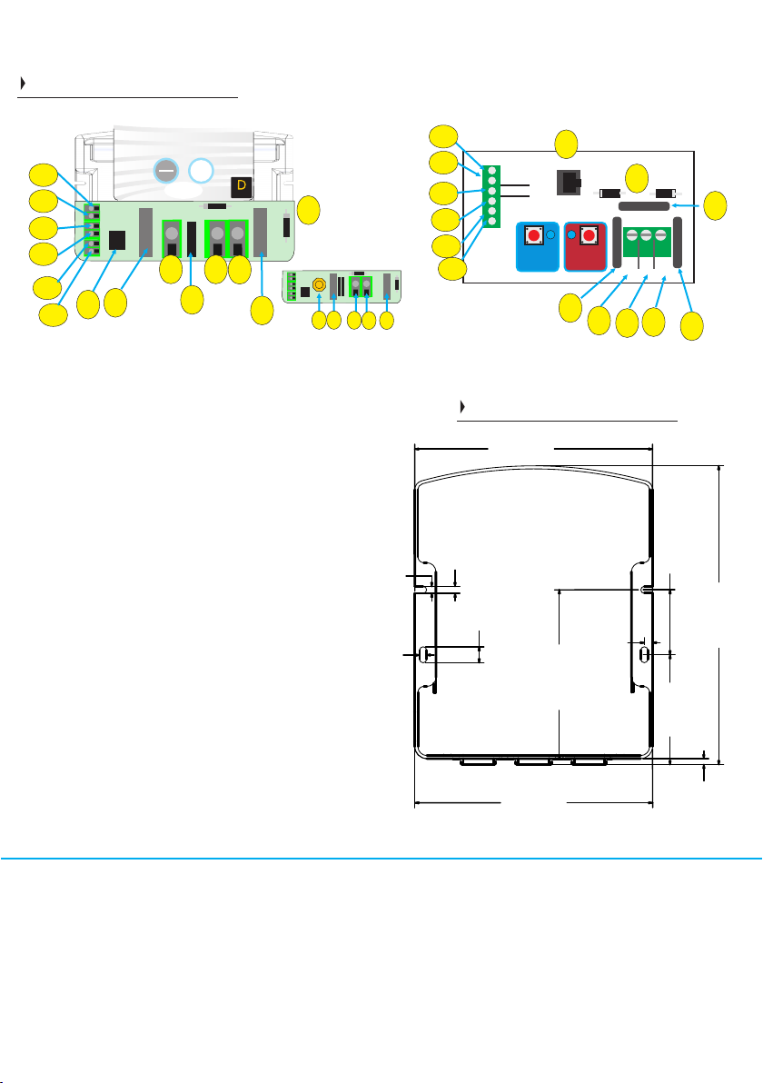
Front label display
1 & 26) ENTER / SETUP and SELECT buttons, used to
adjust settings.
2 & 25) Background light for button, used also to show
unit is operational.
3)-11) The left column of LEDs have 3 different
functions. Firstly, on unit start up the battery type is
displayed. Secondly, after startup it becomes an input
voltmeter. Thirdly, during custom setting the voltage
scale is used to set the voltage - refer to later.
12) This LED has 3 meanings. Firstly, when on battery
type selection mode this is the LiFePO4 lithium battery
indicator. Secondly, on default mode (most times) this
shows the charger is on fast charge mode. Thirdly, if
flashing, then the unit is in standby and was in fast
charge prior to entering standby.
13-15) These LEDs show the battery charge
progression through its cycle.
15) Flash when in standby.
16-24) Has 3 functions: Firstly, on start up they show the
output voltage. Secondly, if an alarm is present the alarm
shows up. Thirdly, this row is used in the custom setup
procedure to set timing functions, voltages and time
factors. Its general function is as an output voltmeter, in
the event 2 LEDs are on the voltages is between the 2
settings, if the top or bottom red LED is on then the
voltage is outside the parameters off the voltmeter.
16) High voltage, if on solid it is high output voltage, if
flashing it is high input voltage.
10
11
13
8
9
7
6
5
4
3
12 14 15
16
17
18
23
24
19 126
21
17) High temp trip, if flashing then high unit
temperature trip.
18) No faults (solid on). Power Pack mode / live
voltage output (flashing).
19) No regen. mode or regen. timer at 0 = solid LED.
Regen on / timer on = flashing LED.
20) Remote Battery sense cable connected (solid).
Battery sense voltage drop in cable outside the 21)
prescribed 1.5V drop maximum, thicker cable
required - LED flashing.
22) Device’s power ability reduced due to high
ambient temperature or voltage drop in output cable
to big. Alarm will be in conjunction with other
information alarm. If flashing unit is in night mode
with reduced power and low fan speed.
23) Low voltage alarm, low voltage on input =
flashing LED. Input alternator not supplying enough
power or failed. Low voltage output = solid LED.
Something consuming a lot of power or unit not
working. No voltage output then LED on solid.
24) If flashing then battery temperature too high.
Solid LED is in SVEM mode - Stationary Vehicle
Engage Mode.
27) Numbers relating to battery custom setup (if
used) this is the charge factor number.
28) Numbers relating to custom setup mode these
numbers relate to timing, i.e. maximum and
minimum time settings.
20
22
Models:
BB1260 / BB122470 / BB123670 / BB124870 /
BB242435 / BB241235 / BB123670 / BB124870
Model:
BB1230
BB122440
Front Panel
Regen timer off (S) / on (fl)
High bat temp (fl) SVEM (S)
4
SELECT
Specification:
12V-12V 60A
Current limiting
Thermostatic control fan
Auto or ignition feed
SETUP
ENTER
Background
light
on
unit
active
www.sterling-power-usa.com
www.sterling-power.com
Designed and
developed
in England
Made in Taiwan
technology
4
L
:
D
U
R
A
A
I
T
B
L
I
G
E
D
:
:
D
C
E
I
M
S
A
G
I
N
N
Y
D
ProDigital
1
2
3
4
5
7
10
11
8
9
14
+
+
+
+
+
+
Remote control
Battery
temperature
sensor
Rem V sense
see side
info
label
SETUP
ENTER SELECT
Reverse
polarity
tell
Enter/Select
buttons under cover
f
u
s
e
Reverse
polarity
tell
f
u
s
e
f u e s
regen
braking
Bat
in + Bat
out +
Neg
-
12
13
6
The mm2 figures have been rounded up to suit European cable availability.
30A
Distance 3m (10 ft) 5m (15ft) 7m (22ft) 8m (25ft) 9m (30ft)
mm2 / 6.0 / 6.0 / 6.0 / 6.0 / 10.0 /AWG 10 10 10 10 8
60A
Distance 3m (10 ft) 5m (15ft) 7m (22ft) 8m (25ft) 9m (30ft)
mm2 / 16.0 / 16.0 / 16.0 / 16.0 / 25.0 / AWG 6 6 6 6 4
Nominal
Fuse size for
input & output
40A
70A
Recommended cable size for current required
Models:
BB1260 / BB122470 / BB123670 / BB124870 /
BB242435 / BB241235
STERLI G
POWER
Models:
BB1230
BB122440
Front Panel II
+
++
+
++
++
+
81
2
3
4
6
7
10
11
12
13
95
14
+
++
++
+
++
53
41
6
BB122470
BB123670
BB124870
BB1260
BB242435
BB241235
4.60
73.00
4.60
158.00
198.51
43.13
158.00
5.50
10.60
4.60
112.13
4.00
199mm(H)
158mm(W)
70mm(D)
units in millimetres (mm)
Under the lid
1) DC output fuse
2) Negative fuse (position, model dependent)
3) DC output to aux battery
4) Common negative
5) DC input from start battery (green connector or
brass nut/bolt - model dependent).
6) DC input fuse
7) Remote control socket
8) Ignition force (immediate activation down to
10V input voltage).
9) Ignition feed connector (on/off)
10) Auto regen. mode (default linked w/ ign feed)
11) Remote battery sense wire to compensate for
voltage drop in cable (optional, does not need to
be used).
12) Battery temperature sensor, optional fit, if not
used product will work on default of 20 deg C
setting.
13) Other wire associated with the temp sensor
as per 12.
14) Reverse polarity tell tale diodes. If damaged,
will show if unit has been reverse polarity and not
under warranty. Position of diodes are model
dependent.
Dimensions
5
100A

Sterling Power Products
Copyright
Engine Starter
Battery
(connected to alternator)
Important
NEGATIVES
should all be common.
We recommend joining
the BB’s neg. to the
starter battery negative.
For improved efficiency.
+
++
++
+
F
U
S
E
2
F
U
S
E
3
Pos
in Pos
out
Bat out fuse
Battery temp
sensor
Remote sense
Remote
socket
ign
ctrl
auto
fuse
fuse
House / Domestic / Aux
Battery Bank
Temp
Sensor on
negative
+
+
+
Link
+
+
+
Auto
Low V
regen. braking
To Ignition feed*
+
+
+
To Ignition feed
Link
(optional)
To Ignition feed*
Auto
Automatic
Activation.
Unit on when input voltage above 13.2V
(input), off below 13.0V (input). If input
voltage is 13.2V - 19.0V the regen. braking
timer begins. This triggers the 240 second
timer which starts when the input voltage
drops to between 11.9V-13.0V. The timer
and voltages can be adjusted. This allows
it to be used with smart alternators /
Regen. Braking.
Ignition feed w/ safe voltage activation
Same as operation mode 1. The only
addition is that an ignition signal is
required for charging. If you have 13.2V+
on the input terminal with no live ignition
feed then the charger is in sleep or
standby mode and not charging.
This signal can be used to turn the charge
on and off if required
Operational Modes
1
2
3
12
3
Unit will work on default setting if temperature sensor not fitted
Ignition Force mode.
For true ignition on/off mode the ‘Link’ should be removed.
As soon as there is a signal (> 4V) on this connector, the unit will
wake up (can take up to 60 seconds) and will start to charge the
output battery. The only limit is the input voltage. It will charge down
to 10V on the input side.
WARNING: In case the alternator / engine is not running or
delivers less than 60A (depends on the charge state of the
output battery) you can discharge your starter battery.
With the Auto link connected and no signal from the ignition then
the BB shall operate identically to Mode 1.
If you have both the link and a live ignition the BB shall operate at
any input voltage (down to 10V). When the ignition feed turns off
the BB shall still charge with Auto Mode (mode 1) parameters.
Ideal if you have shore power charger charging up the input battery
and wish for the BB to turn on and charge the domestic battery etc..
How to get the charger to turn on and operate
- ensure the charger is wired up as depicted above
- when engine is running, the alternator should charge the starter battery.
Because the starter battery is connected to the positive input terminal (Pos in) of the Pro Batt Ultra there should
be at least 13.4V+ (x2 for 24V | x3 for 36V | x4 for 48V) at this terminal, when the engine is running. This shall turn the charger on.
The charger, from default, requires a battery voltage on the positive output terminal (Pos out) in order to start charging, so ensure that there is
battery voltage on the Pos out. If so, the charger shall start charging at the default charging profile (sealed lead acid).
Quick Installation
input cutoff voltage 20s
reset unit to default 30s
1/2 5 seconds
10+ set auto regen
15+ Power supply mode (live)
battery temp
sensor
Temperature sensor
Not obligatory to connect.
If you wish to install, connect the temp
sensor to the negative of the domestic
/ aux. batteries.
When temp sensor senses the
temperature lower than 20Deg C the
voltage shall go up on the charger’s
output and when the temperature is
higher than 20Deg C the voltage.
Sensor shall trip the charger if the
temperature of battery >55DegC
compensates for voltage drop across long cables
++
Neg
+
OEM lock
Numerous OEMs fitters requested the ability to lock
the BB’s functions upon completion of the installation.
This is to prevent their operators playing with the unit
buttons and upsetting the product, in the field.
Factory lock procedure:
Once you have completed the installation and no
more work is required.
Press the left hand button (Setup/Enter) for more than
30 seconds (over 30 blue flashes of the button) then
remove. The 4 corner red LEDs should flash, this
shows lock is now engaged.
Proof of OEM lock:
After lock is engaged push and hold for a few seconds
the right hand button (enter) and the 4 red LEDs will
appear to show the button is not active.
Display / status check: Left hand button can still
select product status (this cannot adjust any of the
settings), it simply allows the customer to access fault
information in event of a problem.
Push the left button for 1 second.
Remove lock and return product to normal
operation:
To remove the lock do a factory reset (explained
earlier in the instructions). This will remove all
programmed features and put the product back, as
new.
6
Quick Guide to the
buttons on the front panel.
Refer to Pages 8 - 11 for in depth procedure
To operate the Pro Batt Ultra
refer to page 7 (next page)
for instructions.
Force unit to float. On/off toggle.
Turn unit on / off toggle.
Battery type select.
Change Operational on/off voltages
Reset unit to default.
30+
20+
Toggle Power Supply mode
(provides live output voltage)
15+
Display software version
SVEM*
Stationary Vehicle Engage Mode
15+ SVEM*
Stationary Vehicle Engage Mode
Pro Batt Ultra starts charging when input is >13.1V.
Turns off when input is <13.0V.
30+ OEM* lock - disables further
adjustment of unit’s functions
OEM lock - press Setup button for 30+ seconds -
4 x red LEDs should light to confirm.
repeat procedure to remove the lock.
this mode prevents operators tampering with the unit’s
settings when in the field. The OEM / fitter can set the
unit up as they desire first, the settings shall be stored,
then they can apply this lock.
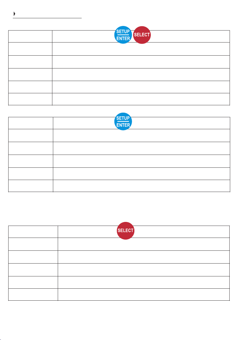
Guide to buttons
Press Length (s)
Action
2-5
Forces unit into float mode. Press again to take out of float mode.
5-10
Turns unit on / off toggle.
10-20
Battery type select - use SETUP / SELECT to toggle between types. Both to confirm.
20-30
Change operational on/off voltages - use both buttons to scroll between voltages.
30+
Reset unit to default - press and hold both buttons for 2 seconds to confirm.
Press Length (s)
Action
0-1
Change to status fault display / back to Voltage display mode.
5-10
Toggles between 1/2 and 1/1 (full) power.
10-15
Set Auto Regen. time - use either buttons to toggle between the preferred time.
15-30
Live output voltage (power supply mode) - press SELECT to change to LED 24.
30+
OEM lock - disables further adjustment of unit’s functions.
Press Length (s)
Action
2-5
Night mode = 1/2 power for 8 hours, then back to full power.
5-10
Enter standby mode. To take out of standby, repeat.
10-15
Display software version (displayed in binary on display).
15+
SVEM - Stationary Vehicle Engage Mode
7

Sterling Power Products
Copyright
Product Information
The Sterling Battery-to-Battery Charger is
a DC to DC charger designed to be put
between a starter battery and an auxiliary /
house / domestic battery. The product’s
advantages are:
5-10+ times faster charging over
i
conventional charging systems (e.g. the
stand alone alternator).
Fool the alternator into working at its
i
maximum ability in order to ensure all its
surplus power is utilized to charge the
auxiliary battery bank to its maximum
capacity without allowing the starter battery
to become discharged.
Allows the correct voltage and charging
i
curve to be selected for you specific
battery chemistry.
Fixes problems associated with vehicles
i
with smart alternators on Euro 5 / 6
engines. It saves your batteries from high
voltage (e.g. Mercedes 15.4V) - gassing
and low voltages (low as 12.2V) - sulfation.
All unwanted side effects to these new
smart alternators.
Fast and easy installation. Simply
i
connect the unit to your starter battery and
your aux battery.
No extra connections to the alternator
i
and no extra wiring for a split charge
system required.
Voltage drops in cabling compensated
i
for.
Several battery-to-battery chargers can
i
be used in parallel for higher output power
or multiple battery banks.
No voltage rises on the alternator or the
i
starter battery. Therefore, no problems with
the engine's management system.
No vehicle warranty issues as the
i
alternator and the main electrical system
remains untouched.
Engine Starter
Battery
(alternator)
+
++
Pos
in Pos
out
Neg
fuse fuse
House / Domestic / Aux
Battery Bank
1) Automatic activation (default setting).
The most common mode, used in 99% of
all installations including vehicles with
Regen. braking system. This means that
the unit is voltage sensitive (no ignition
feed required). The moment the charger is
installed onto an input and output battery it
shall start charging for 120 seconds then turn
off. Only when the input voltage goes to
13.2V-19.0V then the unit will simply start
charging. If the voltage drops below 13.0V the
unit shall turn off. With a caveat, read on.
However, if the input voltage has exceeded
13.2V for 5 seconds the regen. braking timer
is prepped and shall become active if the
input voltage drops down to 12.0V-13.3V.
This timer is 240s (default - can be changed)
and allows the charger to continue charging
at these lower input voltages. If the voltage
drops below 11.9V the charger goes to sleep
irrespective of the timer. If the input voltage
remains between 11.9V-13.0V for over 240s
the charger also goes to sleep. To wake the
charger, the input voltage needs to rise above
13.2V - this shall also reset the regen. braking
timer.
+
+
+
Auto
Ignition
Low V
regen.
braking
Link
2) Ignition feed w/ safe voltage activation
Mode 2 is identical to Mode 1. The only
difference is that it requires a live signal on the
ignition AND the aforementioned input
voltages for it to remain charging. For
example, if you have over 13.2V on the input
terminal with no live feed then the Pro Batt
Ultra shall be in standby. Only once you apply
the ignition feed signal the Pro Batt shall start
charging. The charger turns off when you turn
off your ignition.
This mode is beneficial as it give you more
control over when the charger operates. With
a live ignition and low input voltage the
charger shall still charge for 240 seconds,
then turn off.
How to connect?
Link the Auto and the
Ignition terminals on
the block together,
as shown.
+
+
+
Auto
Ignition
Low V
regen.
braking
How to connect?
Conn ect igni tion
feed to the Ignition
terminal. Can be any
live feed.
+
+
+
Auto
Link
(optional)
3) Pure ignition feed - WARNING flat batt.
If you just connect the ignition feed only to the
bottom connector (remove the link) the BB
shall operate when the ignition is live and turn
off when the ignition is off. There is no timer,
no trigger voltages - only a 10V (20V at 24V)
low voltage trip.
With the link wire connected and the ignition
feed connected the BB shall operate when
the ignition is live. However, it shall also
operate when there is no ignition under the
conditions of mode 1 (above).
This mode is ideal for those who have Euro 6
engines that start up with the alternator off.
Where the starter battery’s voltage does not
exceed 13.3V, but you want the BB to charge.
How to connect?
Connect ignition feed
to Low V regen braking.
Link Auto to ignition
connector.
6
R.B.F
Regenerative
raking riendly B F
STERLI G
POWER
Main Power
Terminals
Auxiliary
Control
Terminals
Fit in a cool dry well ventilated space.
Should be installed by a competent
person, conforming with the laws of the
country. Connect positive cables (in red) to
the terminal block, as shown below. Similarly,
ensure fuses are installed and negatives are
common.
R.B.F
Regenerative
raking riendly B F
R.B.F
Regenerative
raking riendly B F
8Double all voltages for 24V, triple for 36V
and quadruple for 48V.
Ensure the charger is wired up as
depicted above (larger diagram on
previous page). The Pro Batt Ultra shall
light up provided it has battery voltage
across the and neg terminal. If Pos in
Pos out is also connected the unit shall
start charging for 120 seconds (1/2 of the
regen. braking timer). During the first
start up you can change the battery
chemistry profile.
In default mode (1) or mode (2) the Batt
Ultra shall simply turn off and goes to
sleep after 240 seconds (can be
changed) if the input voltage has not
risen above 13.2V. If you WARNING,
have it set to mode (3) (Ignition Force
Mode) and the ignition is live then the
charger shall continue charging until the
input battery drops to (default) x2 10.0V
for 24V. . VERY LOW
In default mode (1) or mode (2) the input
voltage needs to rise to above 13.2V-
19.0V (x2 for 24V) in order for the Batt
Ultra to start charging. This can be
achieved by starting your engine. Above
13.2V, for 5 seconds, the regenerative
braking timer activates (120 sec (first
time after start/wakeup) then 240
seconds default).
There may be a delay of up to 60
seconds before the BB ultra starts.
This is required to complement the
regenerative braking aspect of modern
Euro 5/6+ engi n es - wh e re t he
alternator’s voltage can drop below 13V
for a short period of time. When the
alternator’s voltage rises above 13.2V
the 240 second timer ends (+ reactivates
the timer) and the charger remains
charging.
Basic Operation / Installation
++
Pos
in Pos
out
Neg
fuse fuse House / Domestic / Aux
/ Bow thruster
Main Power
Terminals
If your engine is running and you’re confident your alternator is connected, yet you are only getting 12-13V on the input terminal, please connect the ignition feed to the unit (see right). This shall turn the charger on when the ignition is on.
+
With the Auto link connected and no signal from the ignition then
the BB shall operate identically to Mode 1. If you only connect
the ignition feed but remove the link connector then the unit is
solely ignition feed dependent. Live ignition - the BB is on,
ignition off then the BB turns off. There is a low cut off at 10V
(20V at 24V) on the input. If you have both the link and a live
ignition the BB shall operate at any input voltage (down to 10V).
When the ignition feed turns off the BB shall still charge with
Auto Mode parameters. Ideal if you have shore power charger
charging up the input battery etc.
WARNING - this mode may lead to flat batteries.
Please re-write as it tells you 3 times the same thing.
line to
ignition

Sterling Power Products
Copyright
On first start up all LEDs will light up. A beep should
sound. The fan shall then start running for around 5
seconds. If, after this, 2 red LEDs flash for 8 seconds
you may have a calibration issue and the unit should be
returned to Sterling. If 2 solid red LEDs are on at the top
or bottom then you either have high or low input voltage
(respectively) - check your voltages.
Changing charging profile during startup
After the initial start up an LED on the left panel shall
light up for 5 seconds, this shall indicate the battery type
selected - default is sealed lead acid. This is your
window of opportunity to change the charging profile. If
you have missed the opportunity, you can wait for the
unit to go in to normal operation and follow the
instructions on the right of the page or restart the device.
Hold down both buttons on the front panel (SELECT
and SETUP/ENTER) for more than 10 seconds (less
than 20 seconds!). All LEDs on the left column shall now
flash. By using these two buttons toggle through the
various profiles (see below). The right button is up the
column and the left button takes you down the column.
The LED shall light up demonstrating which profile you
have selected. When the LED has illuminated at your
desired profile simply hold both buttons for a couple of
seconds or simply just leave the charger alone for 30
seconds and it will change. The chosen profile LED
shall then flash. The unit shall then restart and go
through the starting cycle again.
Note - if you can only see LEDs on the right column the
chances are you are in an error mode. This could be
down to: Very low output voltages (<5V), no output
connection, reverse polarity or the device is not
detecting a valid operational mode as the connector
wire is either not connected or the connection
configuration is wrong. Please refer to previous page.
Left and right meter readings.
During normal operation
Out of range voltage values
If voltage exceeds the meter’s range the upper right
LED shall flash. If the voltage falls short of the meter’s
range the lower LED shall flash. If two neighbouring
LEDs, on the voltmeter, are on simultaneously then the
real voltage is between these two parameters.
Example, if LEDs at 14.6V and 14.2V were on then the
approximate voltage shall be ~14.4V.
Low or high output voltages
If the output voltage is below 1V (2V at 24V) or reverse
polarity then the low output voltage LED will flash
(number 23). Similarly, if the output voltage is above
15.5V (31.0V at 24V) the high voltage LED shall flash
(number 16). To resurrect these problems, bring the
voltage above 1V on the output and below 15.5V,
correct the polarity and then restart the device.
Return to factory default: This shall irreversibly
erase all previously entered settings. Press and hold
both buttons for 30 seconds+ and let go. The LED
columns shall alternatively flash. To confirm factory
default press BOTH buttons again for 2 seconds. Once
confirmed, 3 green LEDs on both columns shall flash.
Then, LEDs on the front panel shall light up in a clockwise
pattern. The unit should then reboot with the default
settings. To reject factory default settings, simply let the
LED columns continue alternatively flashing.
To view charger’s status:
Simply hold the SELECT button for 1 second and the right
LED should flash indicating the status of the charger. This
shall flash for 8 seconds. To return quickly, press the
SETUP/ENTER button once.
After unit has gone through its startup sequence the
LEDs displayed should be the input voltage on the left
column and the output voltage on the right column.
Also, the top left LED (number 12) should be on solid
which is the fast charge (bulk) LED.
15.4 V
15.0 V
14.6 V
14.2 V
13.8 V
13.4 V
13.0 V
12.6 V
12.2 V
Input voltage
(x2 for 24V)
Output voltage
(x2 for 24V)
Bulk / Boost Absorb Cond. Float (s) / Standby (fl)
IUOU Battery charge
progress
Charge state ->
Remember it is the voltages which are more important
than our battery types. After installation test the voltage
from the unit is the desired voltage. Ensure you remove
at least 1 wire from the battery temperature sensor as
the product voltage may be higher ( if in cold climate )
or lower ( if in warm climate ) than the preconceived
voltage. The voltage requirements of the battery
company will override our recommendations as it is them
who are supporting the battery warranty.
Changing charging profile during operation.
While the unit is running, simply hold down the SETUP
and SELECT buttons for 10-20 seconds and let go. The
LEDs on the left column shall light up. The procedure
hereafter is the same as above.
*Lithium profile has reverse polarity protection
disabled. **All voltages shall be 0.1V higher for the
first 3 minutes of the chargers operation.
Output Voltage
15.4V
15.0V
14.6V
14.2V
13.8V
13.4V
13.0V
12.6V
12.2V
16
14
12
10
8
6
4
2
0
840
720
600
480
360
240
120
30
0
High Volt in (fl) / out (S)
High temp trip (fl)
No Fault (S) / P.Pack (fl)
Regen timer off (S) / on (fl)
Batt. Sense on (S)
Volt drop sense (fl)
1/2 power (S) / night (fl)
Low Volt in (fl) / out (S)
Bulk / Abs. Cond. Float Min | Abs. | Max
Volts
14.00
14.10
14.40
14.40
14.60
14.80
15.10
15.50
14.40
Custom Charging Profile
Volts
13.70
13.40
13.60
13.80
13.70
13.30
13.60
--------
13.80
Mins
60
60
120
720
60
60
60
240
30
Mins
600
480
480
1440
480
480
360
240
30
Volts
13.85
13.75
14.15
14.00
14.10
14.00
14.30
--------
13.80
Options
1) Gel I
2) AGM I
3) Sealed
4) Gel II
5) AGM II
6) Open
7) Calcium
8) De-sulphation
9) LiFePO4
10) Custom
First Time Use (when wiring up)
If battery temperature sensor is connected then
all voltages are based on 20 Deg C. If sensor
senses less than 20DegC = increased voltage.
Higher than 20DegC = decrease voltage. The
further from 20DegC in either direction leads to
proportional increase or decrease in the
voltage. (x2 for 24V | x3 for 36V | x4 for 48V)
High bat temp (fl) SVEM (S)
9

Sterling Power Products
Copyright
Force unit to operate without output battery connected
( i.e. as a power pack / live output ).
This mode shall allow the unit to operate without needing a
voltage on the output terminal. Hold down SETUP/ENTER
button for 15+ seconds and let go. The boost, absorption
and float LEDs shall flash. A green LED (18) on the right
panel should appear and this indicates that voltage check
is on (default mode) to change it to off (power pack) press
the SELECT button and a red LED (24) below should turn
on. With the red LED on the unit shall now operate without
the need for an output voltage. Press both buttons together
to save this setting or wait 30 seconds for the unit to reboot.
On reboot, the comes on for HIGH BATT TEMP LED(24)
to confirm power pack mode.
Force to Float :
Before accessing float mode please be sure you know
what float mode is and what voltage float mode is for your
profile. Simply hold both buttons down for 2 seconds and
let go. This will lock the charger into float (BLUE LED - top
right - number 15 shall come on). The charger shall now
remain in float and resume bulk/absorption on restarting.
To force the unit out of float repeat the procedure.
Force unit off / on:
This shall deactivate the unit, output goes to 0.0V. Hold
both setup and select buttons for 5 - 9 seconds. LEDs shall
turn off, the Bulk LED (blue) shall flash once every 5
seconds. The unit will remain off, even with normal engine
cycling on and off (although if the unit’s negative is
disconnected from the input battery then it will resume
normal operation on re-connection). To turn the unit back
on, hold the 2 buttons for 5-9 seconds. When OFF, the user
can not access charger’s normal functions.
Force unit to ½ power (stays on until unit is turned off):
This will reduce the units power by about 50%. Hold setup
button only for 5-9 seconds. To confirm the power reduction
LED shall flash 5 times. This function will help reduce noise
in the long term. To return to full power, press the setup
button again for 5-9 seconds.
Force unit to ½ power / low speed fan for 8 hours only
(night mode):
This will reduce the unit’s power by around 50%
for about 8 hours. Hold select button only for
2-4 seconds, power reduction shall be confirmed when the
1/2 power and night LED flashes 4 times. This function will
help reduce fan noise in the short term, in the evenings, for
example. The unit will revert back to full power after 8 hours
automatically. Please note that night mode has to be set
every single time you wish to use it. It can NOT be set to
come on at a certain time daily.
STERLI G
POWER
STANDBY AND SLEEP MODE
NEED TO BE ENTERED AND
EXPLAINED PROPERLY.
Force Options
3
Quick Guide to the
buttons on the front panel
Force unit to float. On/off toggle.
Turn unit on / off toggle.
Battery type select.
Input cut off voltage.
Reset unit to default.
30+
20+
Toggle Power Supply mode
(provides live output voltage)
15+ Display software version
battery temp
sensor
Regen timer adjustment: default 240 seconds
(Regen low voltage timer time).
The default auto Regen time is 240 sec. = 4 min.
The timer is prepped at 13.2V-19.0V on the input.
If the input voltage then falls below 13.0V (x2 for 24V)
the auto regen timer starts to count. If the voltage does
not rise above 13.2V the timer will not reset and the unit
will switch off, however, as soon as the voltage rises
above 13.2V the auto regen timer will automatically reset
to the set value (default = 240sec).
To deactivate the auto regen mode set the auto regen time
to 0 seconds.
By pressing the Setup / Enter only button for more than 10
seconds you will enter the Auto Regen Time Setup. During
the whole Auto Regen Setup the “Absorption” LED will
flash.
1. Absorption LED flashing and actual saved auto Regen
time will be displayed on the right bar. Use the 0 to 840
scale. If the unit is out of the factory the 240 (default)
should be displayed.
2. Press right button to increase or left button to decrease
value.
3. To deactivate the auto regen function set timer value to
0. When happy with your choice either wait 30 seconds or
press both buttons at the same time for 2 seconds.
4. Absorption LED, AGM II and Auto Mode LEDs will flash
10 times to confirm value saving.
5. Unit will restart with new Auto Regen time as default and
will remain there until changed again.
Important: If you have changed the cutoff voltage
remember that the auto regen counter reset functions
must see 0.2V on top of the new cutoff voltage.
I.e. You set the new cut off voltage at 14.0V. To reset
the Auto Regen timer the voltage must rise above
14.2V.
SVEM - Stationary Vehicle Engage Mode.
If your usage pattern is mostly stationary, e.g. You are at
the side of the road and you start the vehicle just to run an
inverter - the problem is that the vehicle’s alternator may
only be at 13.1V (and not give a high voltage boost) and
stay there, in this case the Pro Batt Ultra would not engage
as it needs greater than 13.2V to start. The ideal solution
is to have fitted the ignition feed mode (as per explained in
these instructions). However, if the auto mode was used
and the ignition feed had not been installed then you could
use the Stationary vehicle engagement mode.
This mode allows the product to engage at a much lower
voltage (13.1V) and disengage below (13.0V). To select
this mode: Press SELECT button for 15+ seconds and let
go, No Fault LEDs should be on solid and the Regen timer
LED should be solid. To remove this setting then do the
same again.
Warning: setting is the Stationary Vehicle Engage Mode
operating the unit at voltages which may cause problems
in the winter to the starting of the vehicle - please bear this
in mind we do not have enough history with this setting to
make any guarantees that it shall complement winter
conditions - as low voltages could cause vehicle starting
problems.
10
0
0
0
1
1
0
1
0
1
12 13 14 15
1 26
Display software version
By pressing SELECT for 10-15
seconds certain LEDs on this column
shall briefly illuminate to denote the
software version in binary. From the
top -> down ‘on’ LEDs = 1 and ‘off’
LEDs = 0.
For example, if LEDs 8,7,5,3 are on
then the binary is 000110101 which, in
decimals = 53. Use a calculator.
Desulph
Calcium
Open
AGM II
GEL II
Sealed
AGM I
GEL I
Custom
11
10
9
8
7
6
5
4
3
binary #

Sterling Power Products
Copyright
Press and hold both buttons for 12-14 seconds.
All Left LEDS flash
Press setup to move LED down to custom. Hold both buttons for 2 seconds to confirm.
Opportunity to adjust Fast Charge voltage.
Red Custom LED will flash for 3 seconds to confirm. Custom LED will come on constant,
green Fast charge LED will flash (section 1 on graph).
Adjust Fast Charge by increasing the on label. Select button will increase green voltage
voltage whilst setup will lower.
Wait 30 seconds or press both buttons to confirm this.
Opportunity to adjust conditioning charge voltage
Red Custom LED will come on constant and Green Conditioning LED will flash (section 3
on graph).
Adjust Conditioning Charge by increasing the on label. Select button will green voltage
increase voltage whilst setup will lower.
Wait 30 seconds or press both buttons to confirm this.
Red Custom LED will come on constant and Float LED will flash (section 4 on Blue
graph)
Adjust Float by increasing the on label. Select button will increase voltage green voltage
whilst setup will lower.
Wait 30 seconds or press both buttons to confirm this.
Opportunity to adjust Time factor
Red High Temp LED will come on constant, Green Fast Charge LED will flash and blue
Float will flash (section 1 and 4 on graph).
Adjust Time Factor by increasing or decreasing the on label. Select brown scale (0-960)
button will increase time whilst setup will lower.
Wait 30 seconds or press both buttons to confirm this.
Opportunity to adjust Minimum absorption time factor
Red High Temp LED will come on constant, Absorption LED will flash and Yellow blue
Float will flash (section 2 and 4 on graph).
Adjust Time Factor by increasing or decreasing the on label. Select brown scale (0-960)
button will increase time whilst setup will lower.
Wait 30 seconds or press both buttons to confirm this.
Opportunity to adjust Maximum absorption time factor
Red High Temp LED will come on constant, Green Conditioning LED will flash and blue
Float will flash (section 3 and 4 on graph).
Adjust Time Factor by increasing or decreasing the on label. Select brown scale (0-960)
button will increase time whilst setup will lower.
Wait 30 seconds or press both buttons to confirm this.
A green LED from the middle of each row will flash for around 8 seconds to confirm the
setup is completed. The unit will then restart.
A
B
D
E
F
CUSTOM BATTERY TYPE SETTING (for expert
use only - not required for general operation)
Before proceeding with this, please read and
understand all instructions as it is quite complex and
could take more than one attempt. There are timed
intervals of 30 seconds per setting so it is very
important to know exactly what you require before
starting. If any errors are made simply wait a few
minutes and you can start the cycle again. The
settings offered for adjustment in sequence:
A) Boost / absorption voltage (high voltage charge).
B)Conditioning voltage (medium charge rate
normally between boost and float voltage).
C)Float voltage (no longer charging, this will provide
voltage at a reduced level to maintain the batteries
and provide power for any loads applied).
D) Absorption time factor adjust. The length of time
spent in absorption can be adjusted by a factor 0-18.
This may be beneficial for different battery
chemistries. Gel, for example, tends to absorb
current at a low rate, thus, increasing the length of
time spent in absorption may be beneficial (set
nearer 18). AGM, the reverse (set nearer 0). If in any
doubt, ask your battery retailer or simply use one of
our preset values. To calculate the absorption time
from the time factor simply multiply the factor
number (0-18) by the length of time it takes for the
charging voltage to hit the absorption voltage
(typically 14.4V). If it takes 40 minutes to reach
absorption and you set your ATF to 4 then 4x40mins
= 160 minutes. The maximum time the unit can stay
in absorption is 24 hours 1440 minutes.
E) Minimum and maximum absorption times.
Here you can set the maximum and minimum time
the unit stays in absorption. For example, you may
have AGM that may need a maximum of one hour,
or GEL which could require a minimum of 720
minutes (12 hours).
We recommend that you write down your required
voltages and times in the space below. This is so
you know what to programme during setup.
Desired custom values - make a note.
Boost / bulk / absorption (V) ________
Conditioning (V) ________
Float (V) ________
Absorption Time Factor (0-18) ________
Absorption Minimum (0-960 minutes) ________
Absorption Maximum (0-960 minutes) ________
STERLI G
POWER
Operation
Press and hold both buttons for 10-20 seconds.
All Left LEDs shall flash
Press the setup/select button to move LED down to
custom. Hold both buttons for 2 seconds to confirm.
Opportunity to adjust Fast Charge / Bulk /
Absorption voltage.
Red Custom LED will flash for 3 seconds to confirm.
Red Custom LED will come on constant, Green Fast
Charge LED will flash (section 1 on graph). Adjust
Fast Charge voltage by using the Select and Setup
buttons to go up and down the right LED column to
select the correct Fast Charge voltage. Once content,
wait 30 seconds, or press both buttons to confirm. The
unit shall then proceed to Conditioning charge voltage
(next below).
Opportunity to adjust Conditioning charge
voltage
Red Custom LED will come on constant and Green
Conditioning LED will flash (section 3 on graph).
Likewise, adjust the conditioning voltage by using the
Select and Setup buttons to go up and down the right
LED column to select the correct Conditioning
voltage. Once content, wait 30 seconds, or press both
buttons to confirm. The unit shall then proceed to float
voltage set (next below).
Opportunity to adjust float charge voltage
Red Custom LED will come on constant and Blue
Float LED will flash (section 3 on graph). Likewise,
adjust the float voltage by using the Select and Setup
buttons to go up and down the right LED column to
select the correct Float voltage. Once content, wait 30
seconds, or press both buttons to confirm. The unit
shall then proceed to float voltage set (next below).
Opportunity to adjust absorption time factor
Red High Temp LED will come on constant. Green
Fast Charge LED will flash and will Blue Float LED
flash (section 1 and 4 on graph). This time, adjust the
time by using the Select and Setup buttons to go up
and down the right LED column (refer to the blue scale
scale 0-18) to select the correct time. Once content,
wait 30 seconds, or press both buttons to confirm. The
unit shall then proceed to minimum absorption time
factor (next below).
Why use Absorption Time Factor (ATF)?
ATF is simply a number (0-18) that can be used to
multiply by the length of time the charger takes to
reach the bulk/boost voltage from start. For example,
if the bulk voltage is reached in 10 minutes with the
ATF at 4, then 10mins x (ATF 4) = 40 mins of
absorption.
Custom Settings
11

Sterling Power Products
Copyright
Opportunity to adjust minimum absorption time
factor
Red High Temp LED will come on constant. Yellow
Absorption LED will flash and will flash blue Float
(section 2 and 4 on graph). This time, adjust the time
by using the Select and Setup buttons to go up and
down the right LED column (refer to the brown scale 0-
960) to select the correct time. Once content, wait 30
seconds, or press both buttons to confirm. The unit
shall then proceed to maximum absorption time factor
(next below).
STERLI G
POWER
During this particular setup procedure we have made
the voltage setup LED bar more sensitive so that the
adjustment can be made in 0.1V increments. For
example, for 13.1V the 13V LED is on and the 13.4V
LED is flashing. The same idea for 12.9V. The 13V
LED is on and the 12.6V LED is flashing. Remember
that you are adjusting the whilst Cutoff voltage
simultaneous adjusting the voltage, Charging
Lower voltage trip and the Low voltage trip.
13.4V 13.4V LED ON
13.3V 13.4V LED ON + 13.0V LED FLASHING
13.2V 13.4V LED ON + 13.0V LED ON
13.1V 13.4V LED FLASHING + 13.0V LED ON
13.0V 13.0V LED ON
12.1V 12.2V LED FLASHING
12.0V 12.2V LED FAST FLASHING
To enter the menu press (SETUP/ENTER) &
SELECT for more than 20 seconds.
BOOST CONDITIONING, , and ABSORPTION
FLOAT LEDs will flash to indicate Cutoff voltage
Setting Menu. At the same time the actual Cutoff
voltage will be displayed in the left LED voltage bar
according to the description above. To decrease
voltage press SETUP/ENTER and to increase
voltage press SELECT button.
The range you can choose is Cutoff voltage
between 12.0V-14.6V.
Charging voltage is always 0.2V higher.
Lower voltage trip is always 1.1V lower.
Low voltage trip (Mode 3) is always 3.0V lower.
If you do not touch any buttons for 30 seconds the
default voltage of 13.0V shall be restored and saved.
To confirm your custom voltage you must press
both buttons (SETUP/ENTER) and (SELECT)
simultanously for 2 seconds.
The chosen voltage will be saved and the unit will
restart. If you feel unsure do not touch any buttons.
The default value will be restored automatically.
10
If voltage drops
due to heavy
load in excess
off unit current
ability to support
Charging profile Information displayed on top 4 LEDs on main unit
Fast charge
constant current
mode
Stage 1
High absorption
charge rate constant
voltage mode
Stage 2
Lower conditioning
charge rate constant
voltage mode
Stage 3
Float / Power pack
mode, constant
voltage, full current
accessibility
Stage 4
Backlash voltage. If
charger power exceeded
and battery discharge
unit resets to stage 1
Stage 5
Time (Depending on battery size, type, state of charge and charger battery ratio - Digitally processed)
v
o
l
t
s
Flash
33
3
Modifying input on / off voltage thresholds.
The default input voltage thresholds to operate the Pro
Batt Ultra are as follows:
Activation voltage 13.3V-13.6V - the charger turns on
and charges. If the input voltage drops below 13.3V the
charger stop charging instantly. If the input voltage then
goes back to 13.3-13.6V the charger shall charge again.
13.6V+ - the charger turns on and charges. In addition, the
low voltage timer for regenerative braking activates. So,
now, if the input voltage drops to between 12.0V - Timer
activation V13.3V the default 120 second timer shall begin
and the charging shall continue for 120 seconds. To then
reset this timer the input voltage has to go above 13.6V+
again. If the input voltage only goes to 13.3V-13.6V the
charger shall start charging but shall not reset the timer. If
12.0V - 13.3V is maintained for longer than 120 seconds
the charger turns off.
12.0V - 13.3V - this is the regen. braking operational
window - only activated when the default 120 second timer
has been activated (input voltage at 13.6V+). Provided the
input voltage remains between 12.0V - 13.3V for over 120
seconds the unit shall stop charging.
Low voltage trip V<12V - below 12.0V shall result in the
charger turning off immediately - unless in operation mode
3.
11.5V - Low voltage cut off, applicable only when in
operational mode 3. The
Charging voltage 13.2V
13.0VCutoff voltage
Lower voltage trip 12.0V
Volt. trip w/ ign (Mode 3) 10.0V
CUSTOM INPUT CUTOFF VOLTAGE
SETTING:
(voltages x 2 for 24V)
Here you can adjust the input voltage
setting that prompts the unit into sleep
mode.
This unit has 3 different cut off preset
voltages. In Auto Mode the cut off
default is 13.3V and in Regen Braking
Mode the cut off default is 12.0V. The
higher figure (Auto Mode) and lower
figure (Regen Braking) are both pegged
together by a 1.3V gap. As these figures
are pegged, when you change Auto
Mode you change Regen voltage to be
1.3V lower.
We have designed it, therefore, so you
can only tune the higher voltage (Auto),
this, then changes the lower voltage,
respectively (by 1.3V). The 3rd cut off
voltage is only relevant when in mode 3,
the low voltage trip is pegged at 1.8V
lower than the Auto Mode voltage.
For example, if you want the Regen
cutoff voltage to be 11.7V - set the
higher voltage to 13.0V (11.7V+1.3V).
The low voltage trip (if in mode 3) is then
11.2V.
Adjustment of operational voltages.
The 4 main control voltages below are inextricably linked.
The voltages can only be adjusted as a block (not
individually). For example, if you wish to reduce the Cutoff
voltage by 0.2V then all other voltages in the block shall
reduce by 0.2V.
Opportunity to adjust maximum absorption
time factor
Red High Temp LED will come on constant. Green
Conditioning LED will flash and will flash blue Float
(section 3 and 4 on graph). This time, adjust the time
by using the Select and Setup buttons to go up and
down the right LED column (refer to the brown scale
0-960) to select the correct time. Once content, wait
30 seconds, or press both buttons to confirm.
A from the middle of each row will flash green LED
for around 8 seconds to confirm the setup is
completed. The unit will then restart.
regen braking timer
All 4 voltages are always
linked. This block can be
adjusted by changing the
Cutoff voltage value up and
down. This subsequently
changes the other three
voltages by the same value.
Charging voltage (default 13.2V) (always 0.2V above
Cutoff voltage): At this voltage the charger starts
charging. After 5 seconds above 13.2V the regen braking
timer is set. If the input voltage drops to 11.9V - 13.0V this
timer begins. Timer reset when input voltage is 13.2V+.
Cutoff voltage (default 13.0V): This voltage is only
relevant after the charging voltage has been met and the
charger is charging. When the input voltage drops below
this cutoff voltage the charger stops charging and shall
eventually go to sleep. If the input voltage remains
between 13.0V-13.2V the charger shall continue charging.
The Cutoff voltage is the parameter that the user
changes. Cutoff voltageAs noted, by adjusting the you
change the other three voltages mentioned by the same
amount.
Lower voltage trip (default 11.9V) (always 1.1V below
Cutoff voltage): When the input voltage drops below the
Lower voltage trip the charger turns off. The 11.9V
threshold is only relevant if the is regen braking timer
activated. If not, then the low voltage trip is 13.0V. If in
mode 3, the low voltage trip is 10.0V.
Low voltage trip (default 10.0V) (Mode 3) (always 3.0V
below : Only when in operation mode 3 Cutoff voltage)
does the Pro Batt Ultra work down as low at this voltage.
Input voltage
12

Sterling Power Products
Copyright
Sterling Power Products
H Charge Float
In / Unit Out / Rem
Batt.
V12.2
Temp
Menu
Change
Volts
Select
Audible alarm on/off
hold > 3 sec
On / Off
hold>3 sec
Fault
Absorption
Cond.
menu
scroll
(unidirection)
6
7
5
1
2
3
4
8
9
Volts Select Button (left)
Quick push = back light on.
Short press ~1 second = input
voltage, press again for output
voltage, press again for remote
sense voltage.
Hold for 4 seconds to toggle
between buzzer on/off, bu2
should appear.
Remote control:
cut hole diameter
54mm
1) Volts select button.
2) Voltage displayed is voltage into product.
3) LCD screen with backlight.
4) Fast charge led indicator.
5) Condition battery stage.
Temp Menu Change (right
button)
Quick press = back light on.
Short hold ~1 second = switch
between unit’s temperature
and temperature sensor. If nc
appear it means that the
temperature sensor is not
connected.
Hold for 2 seconds to toggle
night mode on / off, nn should
appear. 1/2 power for 8 hours.
Hold button for 4 seconds
to enter the Setup Menu -
“rt” shall appear.
33
Both Left and Right buttons
Hold both buttons for 2 seconds
to force to float FtF, toggle on / off.
Press and hold both buttons for 4
seconds to enter standby mode,
Stb should appear. Repeat to turn
unit on.
Press and hold both buttons for 6
seconds to turn unit off. oFF shall
appear. Repeat to turn unit on.
Volts
Select Volts
Select
Temp
Menu
Change
Then the actual value. Press “change” button to increase value.
Hold “change” button to accelerate. When max. value reached
it will start with lowest value. Press “select” again to confirm
setting. Press “change” button to increase value. Hold “change”
button to accelerate. When max. value reached it will start with
lowest value. Press “select” again to confirm setting.
“b9b” change voltage from green to blue backlight 12.4 - *
16.0V (default 13.4V). Press “select” .First the lowest and the
hightest value will be displayed. Then the actual value. Press
“change” button to increase value. Hold “change” button to
accelerate. When max. value reached it will start with lowest
value. Press “select” again to confirm setting.
“Led” change LED on time 1 - 600 seconds, 0 = always on,
(default = 60). Press “select” .First the lowest and the hightest
value will be displayed. Then the actual value. Press “change”
button to increase value. Hold “change” button to accelerate.
When max. value reached it will start with lowest value. Press
“select” again to confirm setting.
“uId” display Unit ID. Press “select”. Value will be displayed for
5 sec.
“uSW” display unit software version. Press “select”. Value will
be displayed for 5 sec.
“rSW” display remote software version. Press “select”. Value
will be displayed for 5 sec.
“Loc” Unit lock code = 1 to 999 (default = 00 = unlocked).
WARNING This mode shall lock menu setting options of the
unit by virtue of a pass code, be careful. Press “select” to enter
“Loc” setting. Press “change” button to increase value, hold to
accelerate. Stop when on the number you require and press
“select” button to confirm. The software shall store this number,
then the display shall read: loc -> on -> #. # = number you have
stored. To remove loc, return to loc and re-enter the number,
Press “select” button and the display should read: loc -> off
(green back light). Please make a note of this loc code
here:_______.
“rSt” Resets remote to default values*. Press “select”. “NO”
will be displayed. Press “change” to toggle between “YES” and
“NO”. Confirm by pressing “select”. rSt will display if resetting.
“rSu” Resets the battery charger to default settings. Press
“ ” “NO” “ ”select . will be displayed. Press change to toggle
between YES and . “ ” “NO” Confirm by pressing “select”. rSt will
display if resetting.
“rt” displays remaining absorption or conditioning time
Press “select” button to see value.
“btY” displays battery profile type (0-9). This number
denotes which charging profile the charger is set to. Press
“select” to see value. (Ref: table labelled ‘Battery Chemistry
Selection’ on).
“coU” displays input cut off voltage (the voltage at which the
unit stops charging) (13.4V). Press “select” to see value.
“IoU” display input / output base voltage (12/24V). Press
“select”. First input voltage will be displayed with “in” LED on
for 3 sec. then output voltage with “out” LED on for 3 sec.
change from celcius to fahrenheit or back (default = “C/F” *
celcius). Press “select” button to enter setting. Then press
right button to change between Fahrenheit (FAH) and
Celsius (CEL). Confirm setting by pressing “select” button.
“CL” set current limit to 1/2 or 1/1 (full). Press “select” button
to see actual setting. Press “change” (right) button to
change setting. Press “select” to confirm setting.
“buC” turn Buzzer on / off (default = on). Press “select” to *
see actual setting. Press “change” button to change
between settings. Press „select“ again to confirm setting
Autoscroll on / off (default = off). Press “select” to see “Asc”
actual setting. Press “change” button to change between
settings. Press “select” again to confirm setting.
“Von” Voltage / temp display during standby and sleep.
Toggle between on and off, press “select” (left) button to
select.
“con” change contrast value from 0 to 7 (default = 3). *
Press “select”. First the lowest and the hightest value will be
displayed. Then the actual value. Press “change” button to
change settings. Press “select” again to confirm setting.
change backlight colour . off <- auto -> green -> red -“bLc” *
> blue (default = auto). Press “select” to see actual setting.
Press “change” button to change between settings. Press
“select” again to confirm setting.
“bLt” change backlight time . 1 - 600 seconds, 0 = always *
on, (default = 60). Press “select”. First the lowest and the
hightest value will be displayed. Then the actual value.
“br9” change remote display colour red to green voltage
threshold.* 8.0V-13.3V (default 12.4V). When below 12.4V
display is red and when 12.4V or above the remote goes
green. When Press “select”. First the lowest and the highest
value will be displayed.
6) Charge complete on float.
7) Voltage displayed is volts out of product.
8) Scroll menu button.
9) Screen display showing a unit fault.
Temp
Menu
Change
Temp
Menu
Change
Setup - Menu:
Toggling is unidirectional
to escape menu hold both buttons down until ‘END’
appears. Or, just leave the remote for 10 seconds.
Remote Error Codes
E00 = high input voltage
E01 = high output voltage
E02 = high unit temp
E03 = high batt. temp
E04 = no output voltage
13
Remote Control

14
Fault Finding | Troubleshooting
In the event that you feel there is a problem ( ie you aux battery is not charging ) you need to establish 2
things.
is the battery not charging because there is no charge or because its broken.
first check the voltage at the aux battery with the engine running for at least 2 mins, if you are getting 14-14.8
v then the unit is supplying the correct voltage to charge the batter, so if you getting say 14.4 v at the engine
battery and the battery does not seam to be charger then the simple fact is the battery is either full or scrap,
there is really no other answer to this, .
Assumming you voltage at the nattery is way down say 12 . 2 volts ( with the engine on ) then you need to
check the Battery to Battery charger
To help you with this the unit has a built in a feature to help you , after start up the 2 rows off leds turn into 2
volt meters , for the 60 amp and larger models the left hand side off the LEDS is the voltage in and the right
hand side is the voltage out , for the thirty amp version the top leds are the V in and the Bopttom are the V
out, so by a quick loo at the fron pannel you should be able to see the voltage in and the voltage out . If you
want to confirm these readings using a hand held volt meter then always measure the voltage in and out off
the unit AT THE TEREMINALS OFF THE UNIT, at the early stages off product fault finding the products
voltage are important not the battery voltages .
What should you find.
The most important thing is to confirm you have at least 14 volts going into the unit, if you don't have at least
14 v ( on a boat or vehicle ) the unit simply will not work, so if you only have say 12.5 volts with the engine
running ( for a boat or older vehicle then the alternator is simply not working, if you have 0 volts then there is
no connection between the unit and the starter battery so you inline fuse has blown or a wire has dropped off
. If you have a modern van with a euro 6+ engine then you need to wait a few mins as you may be on
regenerative mode and the alternator may be on low voltage mode, however after about 2-3 mins this voltage
should jump up to over 14 v on the vehicle engine.
so bottom line is if the input voltage is to low then the unit will not engege, you actually need a voltage
greater than 13.9 v to first engage the unit.
if the unit has over 13,9 volts ad there are no leds on then the unit is defective ( do just check the neg to
make sure its ok
assumming there is the correct input voltage to start the unit then we can now move to the output , again
check the voltage , all things being well you should be between 14-15 volts out ( this will depend on battery
load and state off charge ) if you are getting 14-15 volts ( the unit looks like it may be working , then check
the voltage at you aux battery, this should be the same voltage as the unit output battery voltage , if its not ie
2 volts lower then you may jave a defective fuse in the line or the wire has dropped off.
Negatives, people always focus on the positive cables and forget the negatives, this unit is designed for a
comm,on negative system, ie the neg from the auxillary system should be well connected to the neg off the
promart/starter battery, in the event off a vehicle do not relie on the cHASSIE AS THAT TENDS TO BE A BAD
NEG, YOU SHOULD RUN A HEAVY CABLE DIRECT TO BOTH NEGS
ALSO MEASURE THE VOLTAGE FROM THE NEG AT THE AUX BATTERY TO THE NEG AT THE
STARTER BATTERY THIS OBVIOUSLY SHOULD BE O-0,5 V if not check you negs
Firstly, ensure the Pro Batt Ultra (BB) is wired up as per
page 7. Ensure negatives are common and the BB
charger’s negative is connected to the starter battery’s
negative - avoid connecting to chassis negative.
Voltages between common negatives should be ~0V.
Secondly, to test the BB, remove (or turn off) any
secondary charging source like AC to DC battery
chargers or solar chargers going to the battery banks.
Leave the primary charger connected (alternator) -
ensure alternator is working. We also recommend
turning off any loads (inverters etc.).
How to test if the Pro Batt Ultra (BB) is charging:
With engine running (alternator charging), what is the
voltage on the input terminal of the BB? What is the
voltage on the output terminal of the BB? Measure these
voltages at the BB’s terminals, not at the batteries
terminals.
Even though, by default, the BB can work down at 12.0V
on the input; it still requires over 13.3V+ to turn on and
get going. If you are getting alternator voltage at the
input terminal (~14V) and 14V+ on the output terminal
the chances are your BB is working fine. If little to no
current is passing through the charger at these voltages
then the batteries are either full or they are deceased. If
the output voltage is between 13V-14V (but rising) then
you could have a situation where the output batteries
were very low in charge (or large in capacity) and the
charger shall be charging at maximum current. Provided
the voltage continues rising the BB is charging.
If your output voltage is less than 13V and your input
voltage is healthy, it could be three things:
1) You have a large load on your output bank - turn load
off.
2) The BB has been turned off - hold SETUP/ENTER +
SELECT button for 5 seconds and let go, to turn on
again.
3) The BB is not working.
If your input voltage is less than 13V, it could be
several things:
Automotive: Your alternator’s voltage is at
less than 13V (the alt. is regenerative braking mode -
sometimes expected on modern Euro 5/6+ engines) -
take vehicle for drive and measure alternator’s voltage
and set up the BB to suit these needs. All vehicle
manufactures have their own software / characteristics
for regen. braking.
Automotive or Marine: If your alternator’s
voltage is ~14V then check continuity between the
alternator’s B+ terminal and the starter battery. If you are
getting ~14V on starter battery then check continuity
between starter battery and BB input terminal.
Automotive or Marine: If your alternator’s
voltage is 0-13V (starter battery voltage) then alternator
may have failed. Or, requires increase rpm of engine,
possible belt slip.
Is your output voltage slightly higher or lower than
expected - even with no loads / chargers on?
Check if you have the temperature sensor connected.
If so, no problems leaving it there, it is simply voltage
compensating for when the temperature at the sensor
is lower or higher than the benchmark 20DegC (69F).
If lower, then the voltage shall rise and vice versa. The
further from 20DegC in either direction leads to
proportional increase or decrease in the voltage.
Possible, voltage drop across long cabling / fuse
holder / diode. Use our remote sense connection on
the unit - refer to page 6, yellow wire.
LED 16 flashing red - over voltage on input. This LED
comes on if there is 19V for more than 3 seconds on
the input terminal. Check the voltage at the input.
Possible regulator fault, or alternative charger’s
voltage is too high.
LED 16 solid red - Over voltage output. There is 16V+
for more than 3 seconds on output terminal. Check the
voltage at the output. Turn charger off, if voltage drops
when off and rises again when turned on the possible
charger fault. If 16V+ irrespective of charger being on
then check alternative charging source.
LED 17 flashing red - over temperature. Unit has
become too hot and switches off. Possible defective
fan. Or, high ambient temperature, ensure good
ventilation or the charger’s vents may be blocked
LED 21 flashes yellow - high voltage drop across
output cable. When the battery voltage sensor is
connected the device has detected too high a voltage
drop between the output and the positive terminal of
the battery (>1.5V). Verify that the cable thickness is
sufficient. Possibly the terminals are corroded or bad
connection. Also check if the cable is actually
connected to the battery.
LED 22 solid yellow or flashing - the charger is in 1/2
power. It has either been manually forced into 1/2
power mode or night mode (refer to page 9). Or, the
charger has engaged1/2 power mode itself due to the
device’s temperature (> 85°C). In this case, check the
fan and the ambient temperature. Possibly the
installation is not properly ventilated. Make the
adequate ventilation.
LED 23 solid yellow or flashing - undervoltage. If the
LED flashes, the input voltage is too low. Check the
alternator or the charging source of the starter battery.
If the LED is solid, the output voltage is very low -
output batteries are likely to be defective.
LED 24 flashing red - high battery temperature. The
unit has shut down due to excessive battery
temperature (> 55°C). Either the battery is defective or
the ambient temperature is too high. Provide adequate
ventilation.
Product Specifications
BB1230 BB1260 BB122470 BB123670 BB124870 BB241235 BB242435
Input Voltage (V DC) 11 - 20 11 - 20 11 - 20 11 - 20 11 - 20 22 - 40 22 - 40
Input Current (A) 30 60 70 70 70 35 35
Battery types (all models)
IP rating IP21 IP21 IP21 IP21 IP21 IP21 IP21
Ignition Protected Yes Yes Yes Yes Yes Yes Yes
Quiescent Current (mA) 1 1 1 1 1 1 1
Battery Connector WJ116VW WJ116VW WJ116VW WJ116VW
Weight (Kg) 1.2 1.4 1.4 1.4 1.4 1.4 1.4
Dimensions (LxWxD) mm 190 x 160 x 50
AGM (2) | GEL (2) | SEALED | OPEN | LiFePO4 | CALCIUM | CUSTOM
8mm input | WJ116VW output
190 x 160 x 70
If battery temperature sensor is connected then
all voltages are based on 20 Deg C. If sensor
senses less than 20DegC = increased voltage.
Higher than 20DegC = decrease voltage. The
further from 20DegC in either direction leads to
proportional increase or decrease in the
voltage. (x2 for 24V | x3 for 36V | x4 for 48V)

Sterling Power Products
Copyright
Your 100 % satisfaction is our goal. We realise that every customer and circumstance is unique. If you
have a problem, question, or comment please do not hesitate to contact us. We welcome you to contact us
even after the warranty and return time has passed.
Product Warranty:
Each product manufactured by Sterling Power comes with at least a 2 year limited factory warranty. Certain
Products have a warranty period of time greater than 2 years. Each product is guaranteed against defects in
material or workmanship from the date of purchase. At our discretion, we will repair or replace free of
charge any defects in material or workmanship that fall within the warranty period of the Sterling Power
product. The following conditions do apply:
- The original receipt or proof of purchase must be submitted to claim warranty. If proof cannot be
located a warranty is calculated from the date of manufacture.
- Our warranty covers manufacture and material defects. Damages caused by abuse, neglect,
accident, alterations and improper use are not covered under our warranty.
- Warranty is null and void if damage occurs due to negligent repairs.
- Customer is responsible for inbound shipping costs of the product to Sterling Power either in the
USA or England.
- Sterling Power will ship the repaired or warranty replacement product back to the purchaser at
their cost.
If your order was damaged in transit or arrives with an error, please contact us ASAP so we may take care
of the matter promptly and at no expense to you. This only applies for shipping which was undertaken by
our company and does not apply for shipping organised by yourself. Please do not throw out any shipping
or packaging materials.
All returns for any reason will require a proof of purchase with the purchase date. The proof of purchase
must be sent with the returned shipment. If you have no proof of purchase call the vendor who supplied you
and acquire the appropriate documentation.
To make a claim under warranty, call our customer care line at ( USA 1-(207)-226-3500, England 01905
771771). We will make the best effort to repair or replace the product, if found to be defective within the
terms of the warranty. Sterling Power will ship the repaired or warranty replacement product back to the
purchaser, if purchased from us.
Please review the documentation included with your purchase. Our warranty only covers orders purchased
from Sterling Power. We cannot accept warranty claims from any other Sterling Power distributor. Purchase
or other acceptance of the product shall be on the condition and agreement that Sterling Power USA LLC
and Sterling Power LTD shall not be liable for incidental or consequential damages of any kind. Some states
may not allow the exclusion or limitation of consequential damages, so, the above limitations may not apply
to you. Additionally, Sterling Power USA and Sterling Power LTD neither assumes nor authorizes any
person for any obligation or liability in connection with the sale of this product. This warranty is made in lieu
of all other obligations or liabilities. This warranty provides you specific legal rights and you may also have
other rights, which vary from state to state. This warranty is in lieu of all other, expressed or implied.
Customer Service & Warranty
Sterling Power USA
Warranty Service Center
www.sterling-power-usa.com
Sterling Power Products Ltd
England
www.sterling-power.com
STERLI G
POWER
15

Sterling Power Products
Copyright
STERLI G
POWER
Pro Batt Ultra
Batterie-zu-Batterie-Ladegerät
Copyright © 2016
Sterling Power
V 1.0 März 2016
Starter
zu ladende
Batteriebank
UNBEDINGT LESEN!
Dieses Gerät hat viele Funktionen und es erscheint eventuell
langweilig, das Gerät zu installieren und einzustellen.
Für 90% aller Anwendungen ist dieses auch nicht nötig. Schließen
Sie das Gerät gemäß der rechten Skizze an. Das Gerät schaltet dann
automatisch an, sobald die Spannung am Eingang über 13,2V
(26,4V) steigt. Fällt die Spannung unter 13V (26V), schaltet das Gerät
nach 2 Minuten automatisch wieder ab. Die Ladespannung beträgt
14,4V (28,8V) was für die meisten Batterien korrekt ist.
Standardeinstellung ist für automatische Rekuperation (EURO 6).
Lesen Sie unbedingt die Sicherheitshinweise und allgemeinen
Bedingungen! Auch empfehlen wir Ihnen die Installation durch
einen Fachbetrieb durchführen zu lassen.
Bestell-Nr:
BB1230 12V-12V 30A
BB1260 12V-12V 60A
BB122470 12V-24V 70A
BB123670 12V-36V 70A
BB124870 12V-48V 70A
BB242435 24V-24V 35A
BB241235 24V-12V 35A
Batterie-Temperatur-
Sensor
Für aktuelle Informationen:
Europe: www.sterling-power.com
North America: www.sterling-power.usa.com
BEDIENUNGSANLEITUNG
Sterling Power Products
H Charge Float
In / Unit Out / Rem
Batt.
V12.2
Temp
Menu
Change
Volts
Select
Audible alarm on/off
hold > 3 sec
On / Off
hold>3 sec
Fault
Absorption
Cond.
Optionale
Fernbedienung
technology
4
D
U
:
L
R
A
A
T
I
B
G
L
I
E
D
:
:
D
C
I
E
S
M
I
A
G
N
N
Y
D
ProDigital
RoHS
compliant R.B.F
Regenerative
raking riendly B F
Test Report
Jedem Gerät liegt ein Testreport bei.
Bewahren Sie diesen Report auf.
Der Testreport wird im Falle eines Garantieanspruchs
benötigt und muss mit dem Gerät zurückgeschickt werden.
+
++
Pos
in Pos
out
Neg
fuse fuse
Batterie-
anschluss

Sterling Power Products
Copyright
STERLI G
POWER
Inhaltsverzeichnis
Hinweise und Sicherheitsinformation Seite 3
Benutzung dieser Anleitung
Copyright
Wartung und Reparatur
Sicherheit und Vorsichtsmaßnahmen
Beschriftungs-Erklärung Seite 4 - 5
Vordere Beschriftung
Beschriftung unter dem Deckel / Techn. Daten
Emfpohlene Kabelstärken und Sicherungen
Schnell- Installationshilfe Seite 6
Standard Anschluss Skizze
Basis Operations-Modus
Ausführliche Installationshilfe Seite 7 - 8
Installations-Diagramm
Montage
Der korrekte Anschluss
Einstellungen Seite 9
Batterieprofil ändern
Individuelles Batterieprofil erstellen
Weitere Einstellungen Seite 10 - 11
Fehleranzeigen und mögliche Ursachen Seite 11
Ladekennlinie, Battierprofile + Sensor Seite 12
Fernbedienung Seite 13 - 14
Pflege, Wartung und Garantie Seite 15

Sterling Power Products
Copyright
STERLI G
POWER
4
2
Über diese Anleitung
Diese Bedienungsanleitung muss vor der Installation
des Gerätes gelesen werden. Verlieren Sie diese
Anleitung nicht und verwahren diese an einem
sicheren Platz. Eine aktuelle Form dieser Anleitung
kann auf unserer Webseite gefunden werden. Bevor
Sie uns bzgl. einer Frage kontaktieren, sehen Sie bitte
nach, ob Sie die aktuelle Anleitung vorliegen haben.
Die Installation sollte von einem qualifizierten
Fachmann/-frau ausgeführt werden, der/die sich mit
den gültigen Vorschriften auskennt.
Sterling Power’s Garantieversprechen
Eine ausführliche Erklärung zur Sterling Garantie
können Sie auf der letzten Seite finden. Auf unserer
Webseite „ “ können die www.sterling-power.com
aktuellen Garantieerklärungen eingesehen werden.
Copyright and Abschriften
Copyright © 2015 Sterling Power. Alle Rechte sind in
unserem Eigentum. Vervielfältigung, Auszug und
Digitalisierung ist verboten. Wenn Sie Teile dieser
Anleitung verwenden möchten, kontaktieren Sie uns.
Haftung
Sterling Power haftet nicht für :
ŸFolgeschäden aufgrund der Nutzung / des
Gebrauchs dieses Gerätes
Ÿmöglichen Fehlern in der Anleitung oder deren
Folgen
Veränderungen
Das Gerät darf nicht verändert, modifiziert oder
eigenständig repariert werden. Bei jeglicher
Veränderung des Gerätes erlischt der
Garantieanspruch.
Verwendungszweck und -art:
ŸZur Gleichstrom-zu-Gleichstrom Tranformation.
ŸZur Gleichstrom-Limitierung.
ŸKabel benötigen ausreichend dimensionierte
Sicherungen.
ŸDarf nur in einem gut belüfteten, trockenen und
staubfreien Ort betrieben werden..
ŸDie Anleitung sollte vor der Installation gelesen
werden.
Sicherheits Symbole
ŸBeispiel - WARNUNG. Benutzen Sie das
Produkt niemals in Umgebungen, wo die
Möglichkeit einer Gas oder Staub-Explosion
besteht oder brennbare Produkte sind..
Generelle Wartung und Reparatur.
Das Gerät muss bei einer Wartung durch einen
Fachelektriker vom Strom komplett getrennt werden.
Zur Reparatur senden Sie das Gerät bitte zu uns.
Generelle Sicherheits- und Installationshinweise.
ŸInstallieren Sie das Gerät nur in ausreichend
belüfteten Räumen. Das Gerät darf nicht Regen,
Schnee, Dunst, Sprühnebel, Rauch oder extrem hoher
Feuchtigkeit ausgesetzt werden. Auch darf es nicht
abgedeckt werden und die Lüftungsöffnungen müssen
offen bleiben.
ŸDer Geräte-Minus-Anschluss muss mit dem
allgemeinen Minus verbunden werden. Es können
nicht 2 komplett isolierte Batterien geladen werden, da
der Negativ der geladenen und der Quell-Batterie
immer einen gemeinsamen Minus haben.
ŸIm Falle eines Feuers nutzen Sie einen
Feuerlöscher.
ŸAchten Sie darauf, dass das Gerät weder verpolt
noch kurzgeschlossen wird..
ŸSchützen Sie alle Verbindungen mit ausreichend
dimensionierten Sicherungen.
ŸÜberprüfen Sie alle Verbindungen jährlich.
ŸVermeiden Sie den Kontakt mit feuchten/nassen
Händen.
ŸAchten Sie auf eine feste und korrekte Installation
des Gerätes an einer Wand.
ŸDas Gerät sollte nur von einem Fachbetrieb
installiert werden.
Batterie & Sicherheit
Extrem starke Ladung oder Entladung oder hohe
Spannungen können zu Schäden an der Batterie
führen. Überschreiten Sie nicht die empfohlenen
Ladespannungen der Batterien, welche Sie vom
Hersteller der Batterien erfahren. Sollten Sie Kontakt
mit Batteriesäure bekommen, waschen Sie sofort die
Kontaktflächen mit Wasser und Seife. Sollten Ihre
Augen betroffen sein, spülen Sie diese für 20min. mit
Wasser aus und gehen Sie sofort zu einem Arzt oder
ins nächstgelegene Krankenhaus.
ACHTUNG
WARNUNG
EXPLOSIONS-
GEFAHR
3

Sterling Power Products
Copyright
STERLI G
POWER
4
4
10
11
13
8
9
7
6
5
4
3
2
1
12 14 15
16
17
18
19
20
21
22
23
24
25
26
27
28
Beschriftung
1 & 26) ENTER / SETUP und SELECT Taster, werden
zur Einstellung benötigt.
2 & 25) Taster Hintergrundlicht. Wenn es leuchtet sind
die Taster aktiv.
3)-11) Die LED Reihe hat 3 Funktionen.
1. Während des Startvorganges wird der Batterietyp
angezeigt.
2. Während des Betriebs zeigt es die
Eingangsspannung an.
3. Bei der Programmierung des individuellen
Batterietyps wird die Spannung angezeigt.
12) Die LED hat 2 Funktionen. 1. Während des
Startvorgangs wäre es die LED für LiFePo Lithium
Batterien. 2. Während des Ladevorganges zeigt es die
Ladestufe an.
13-15) Anzeige der Ladestufe.
15) Blinkt im Standby Modus.
16-24) Die LED Reihe hat 3 Funktionen:
1. Anzeige der Ausgangsspannung
2. Im Falle eines Fehlers oder beim Umschalten in die
Statusanzeige werden Stati oder Fehler angezeigt.
3. Zur Programmierung des individuellen Batterietyps
dienen die LEDs zur Anzeige des Wertes.
Status- und Fehleranzeigen
16) Überspannung: Zu hohe Eingangsspannung =
blinken; zu hohe Ausgangsspannung = an
10
11
13
8
9
7
6
5
4
3
12 14 15
16
17
18
23
24
19 126
21
20
22
Modelle:
BB1260 / BB122470 / BB123670 / BB124870 /
BB242435 / BB241235
Modell:
BB1230
17) Zu hohe Temperatur des Gerätes = blinken
(Lüfter defekt oder blockiert?)
18) Keine Fehler = an,
Modus ohne Ausgangsspannungsprüfung =
blinken.
19) Rekuperations-Modus aus = LED an
Rekuperations-Timer auf null = LED an
Rekuperations-Timer aktiv = LED blinkend
20) Batterie-Temperatur-Sensor angeschlossen und
OK.
21) Spannungsabfall auf dem Spannungs-Sensor
Kabel zu hoch (> 1,5V). LED blinkt. Spannung wird
jetzt am Ausgang geregelt.
22) Leistung auf ca. 50% reduziert = LED an
Gerät im aktiven Nachtmodus = LED blinkt.
23) Zu geringe Eingangsspannung = LED blinkt.
geringe Ausgangsspannung = LED an
Batterie-Temperatur zu hoch = LED blinkt.24)
27) Dieses sind die Faktoren der
Ladezeitberechnung bei der Einstellung des
individuellen Batterietyps.
28) Diese Zahlen geben die Zeit in Minuten wieder
bei der Einstellung der minimalen und maximalen
Ausgleichsladungszeit des individuellen Batterietyps
an.

5
+
++
++
+
+
++
1
2
3
4
5
6
7
10
11
12
13
8
9
SELECT
Specification:
12V-12V 60A
Current limiting
Thermostatic control fan
Auto or ignition feed
SETUP
ENTER
Background
light
on
unit
active
www.sterling-power-usa.com
www.sterling-power.com
Designed and
developed
in England
Made in Taiwan
technology
4
L
:
D
U
R
A
A
I
T
B
L
I
G
E
D
:
:
D
C
E
I
M
S
A
G
I
N
N
Y
D
ProDigital
14
Zur Entfernung der Abdeckung drücken Sie bitte an beiden Seiten die Laschen
max. 4mm ein. Dann sollte sich die Abdeckung lösen.
1
2
3
4
5
7
10
11
8
9
14
+
+
+
+
+
+
Remote control
Battery
temperature
sensor
Rem V sense
see side
info
label
SETUP
ENTER SELECT
Reverse
polarity
tell
Enter/Select
buttons under cover
f
u
s
e
Reverse
polarity
tell
f
u
s
e
f u e s
regen
braking
Bat
in + Bat
out +
Neg
-
12
13
6
Empfohlene Kabelstärken und Sicherung
Modelle:
Bb1260 / BB122470 / BB123670 / BB124870 /
BB242435 / BB241235
STERLI G
POWER
Modell:
BB1230
einfache
Entfernung
1m
2m
3m
4m
5m
Empf.
Sicherung
30A Gerät
6mm²
10mm²
16mm²
16mm²
25mm²
50A
60A Gerät
16mm²
25mm²
25mm²
35mm²
35mm²
100A
Spannungs-
einbruch wenn
Stromabnahme
größer ist als
Leistung des
Gerätes
Ladeprofilinformation
Schnellladung
Maximaler Strom
Stufe 1
Ausgleichsladung
Konstante Spannung
Stufe 2
Konditionierung
Konstante Spannung
Stufe 3
Erhaltung
Konstante
Spannung
Stufe 4
Rückschaltung
in Stufe 1
Zeit (Abhängig von der Batteriegröße, Typ, Ladezustand und Ladestrom)
v
o
l
t
Technische Daten:
(bei 24V x2, 36V x3, 48V x4)
Max. Eingangsspannung: 20V
Spannungs-Arbeitsbereich: 11 - 19V
Ausgangsspannungsbereich: 12 - 16V
Max. Eingangsstrom:
BB1230 30A
BB241235/BB242435 35A
BB1260 60A
BB122470/BB123670/BB124870 70A
Max. Ausgangsstrom :
BB1230 ca. 23 - 30A
BB1260 ca. 50 - 60A
BB122470/BB242435 ca. 30 - 35A
BB123670 ca. 18 - 22A
BB124870 ca. 15 - 17A
Bb241235 ca. 60 - 70A
Eigenstromverbrauch (aktiv): 80 - 120mA
Fernbedienung (aktiv): +40 - +60mA
Stromverbrauch Schlafmodus: 1,5 - 0,8mA
(mit angeschlossener Fernbedienung = 2,5mA)
Der Stromverbrauch im Aktiv-Modus ist abhängig
von der Anzahl der LEDs, welche leuchten.
Unter der Abdeckung
1. DC Ausgangs-Sicherung
2. Boost Sicherung
3. DC Ausgang zur Batterie
4. Gemeinsamer Minus-Anschluss
5. DC Eingang von der Starter-Batterie
6. DC Eingangs Sicherung
7. Fernbedienungs-Anschluss
8. Direktbetriebs-Anschluss
9. Zündung-Aktiv-Signal (Brücke 9-10 muss
entfernt werden)
10. Gebrückt mit 9 = Automatik Betieb
11. Batterie-Spannungs-Sensor Anschluss
12 + 13 Batterie-Temperatur-Sensor
Anschluss
This manual suits for next models
5
Table of contents
Languages:
Other Sterling Power Batteries Charger manuals

Sterling Power
Sterling Power Aquanautic 8A User manual

Sterling Power
Sterling Power Portable Battery Charger B124 User manual

Sterling Power
Sterling Power ProSport 5 Series Programming manual

Sterling Power
Sterling Power Portable Battery Charger B121 User manual

Sterling Power
Sterling Power BB1224120 User manual

Sterling Power
Sterling Power Pro Batt Ultra User manual

Sterling Power
Sterling Power BB1240 User manual

Sterling Power
Sterling Power BBWS1225 User manual

Sterling Power
Sterling Power BB1230 User manual

Sterling Power
Sterling Power B127 User manual


