Circontrol Genion One User manual

Genion One
Installation
Manual

THIS PAGE HAS BEEN INTENTIONALLY LEFT BLANK

COPYRIGHT INFORMATION
This document is copyrighted, 2023 property of Circontrol S.A. All rights reserved.
Circontrol, S.A. reserves the right to make modications, at any time and without prior
notice, to the products described in this instruction manual.
No part of this manual, in whatever form, may be reproduced, copied, translated or
transferred to third parties without the prior permission of the original manufacturer.
The information in this manual is intended to be accurate and reliable. However, the
original manufacturer assumes no liability for its use or for any infringements that may
be committed against third parties as a result of its use.
All product names and trademarks belong to their respective owners.
Genion One
Installation Manual
THIS PAGE HAS BEEN INTENTIONALLY LEFT BLANK

0

Here is the
guide to install
and congure
Genion One
1 - Introduction 04
A - Checks upon delivery 05
2 - Before Installation 06
A - Prior recommendations 07
3 - Overview 08
4 - Equipment Installation 10
A - Wiring diagram 11
5 - Operation 12
A - LED indicators 12
B - Reset 14
6 - Communications 16
A - RS-485 Communications 16
B - WiFi communications 17
C - Ethernet communications 17
7 - Conguration website 18

A - Connection 18
B - Dashboard 20
C - Calendar 24
D - Settings 26
E - System information 26
F - Communications 28
G - Installation 30
8 - Technical Characteristics 34
9 - Need Help? 38

THIS PAGE HAS BEEN INTENTIONALLY LEFT BLANK

04
Genion One - Installation Manual
INFORMATION
Useful information to take into account.
• Read all instructions before
using and setting up the
equipment.
• Do not modify the equipment.
If you make changes,
CIRCONTROL will reject any
liability and the warranty will
be void.
• You must fully comply with the
electrical safety regulations
applicable in your country.
• Do not repair or tamper with
the equipment while it is
connected to a power supply
1
This manual provides information about how to install, congure and use
the Genion One.
It contains all the necessary information for safe usage and help to get the
best performance from the product with step-by-step setup instructions.
THE FOLLOWING SYMBOLS ARE USED IN THIS DOCUMENT
TO INDICATE IMPORTANT SAFETY INFORMATION
ATTENTION
Indicates that special attention should be paid to the
point indicated.
DANGER!
Indicates that property damage may occur if
appropriate measures are not taken.
i
IMPORTANT SAFETY INSTRUCTIONS

05
Introduction
Genion One is a product that allows you to manage the energy of an electrical
system with a photovoltaic self-consumption system and an electric vehicle
charging point. It was created with the objective of optimising energy usage
in a system, specically the contracted power and the surpluses produced
by the self-consumption system, regulating the electric vehicle charging.
This manual explains the use of the web application that controls the
operation of this equipment, as well as the previous steps to establish the
connection.
Information is also included on the contents of the manual and how to use it
effectively to ensure correct installation and proper operation of the device.
It is important to read the instructions carefully before starting the installation
and ensure that all system requirements and applicable legal and safety
requirements are met.
Checks upon delivery
A
Upon delivery of the equipment, check the following points:
• The equipment corresponds to the specications of your order.
• The equipment has not been damaged during transport.
• Perform an external visual inspection of the equipment before
connecting it.
• Check that it is equipped with a quick installation guide.
If you notice any delivery issues, immediately
contact the carrier and/or CIRCONTROL's after-
sales service.

06
Genion One - Installation Manual
2

07
Before installation
Previous recommendations
A
The Genion One must be installed by authorised and qualied professional.
Before handling, modifying the wiring or replacing the equipment, the power
supply must be disconnected. Handling it while it is connected is hazardous.
It is essential to keep the cables in perfect condition to avoid accidents or
damage to people and/or property.
Theequipmentmanufacturershallnotbeliableforanydamageswhatsoever
in the event that the user or installer does not heed the warnings and/or
recommendations indicated in this manual, nor for damages resulting from
the use of non-original products or accessories.
If an anomaly or malfunction is detected in the equipment, do not perform
any operation on it.
Check the environment you are in before initiating connection: Do not make
connections in hazardous or explosive environments.
Fortheequipmenttobeusedsafely,itisessentialthat
the people who handle it follow the safety measures
stipulated in the regulations of the country where
it is being used, wearing the necessary personal
protective equipment and heeding the various
warnings indicated in this instruction manual.
08
Genion One - Installation Manual
3
Device characteristics:
• RS-485, Ethernet and WiFi connections.
• 6 LED indicators.
• A Web application that allows you to congure and
visualise all the parameters of the home system in real
time via WiFi or Ethernet.
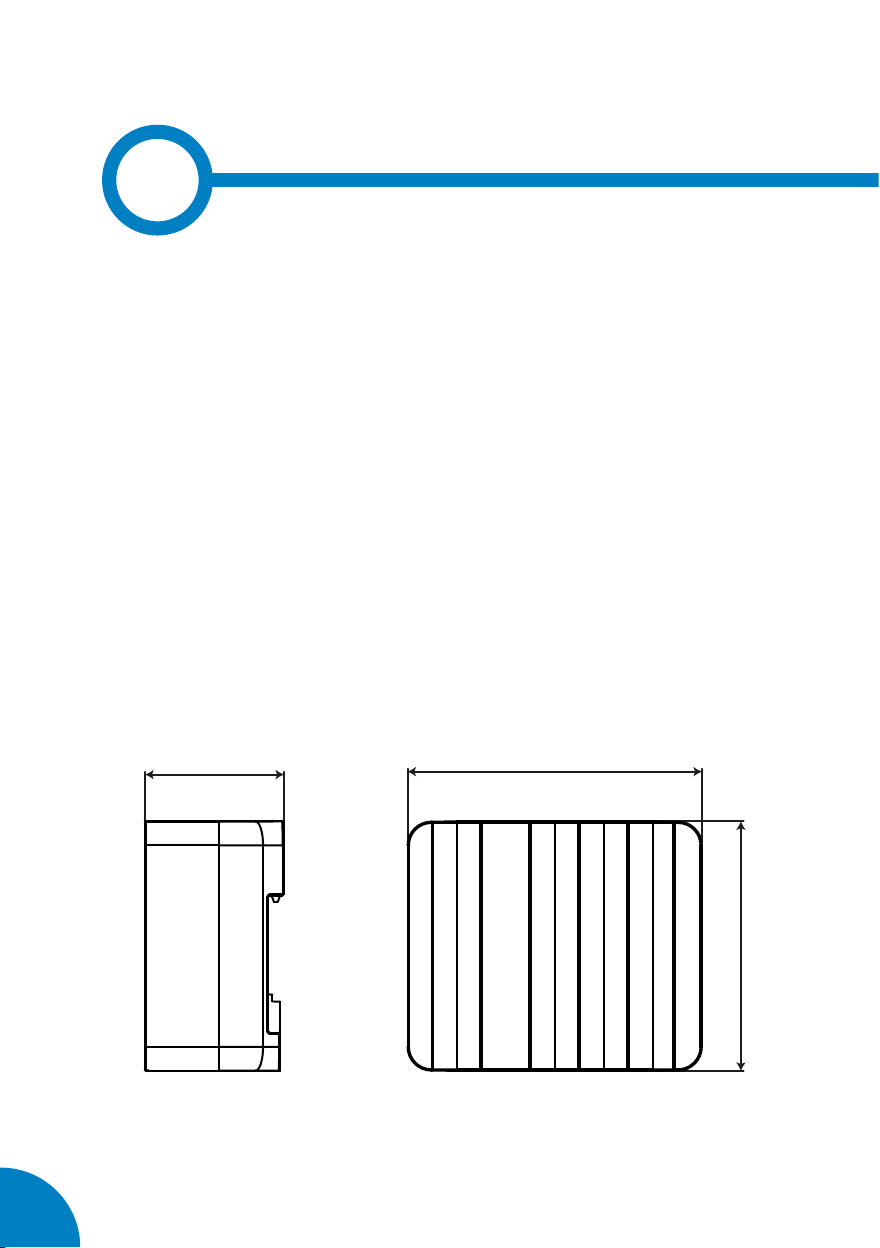
105
89
49.5
Device dimensions:
09
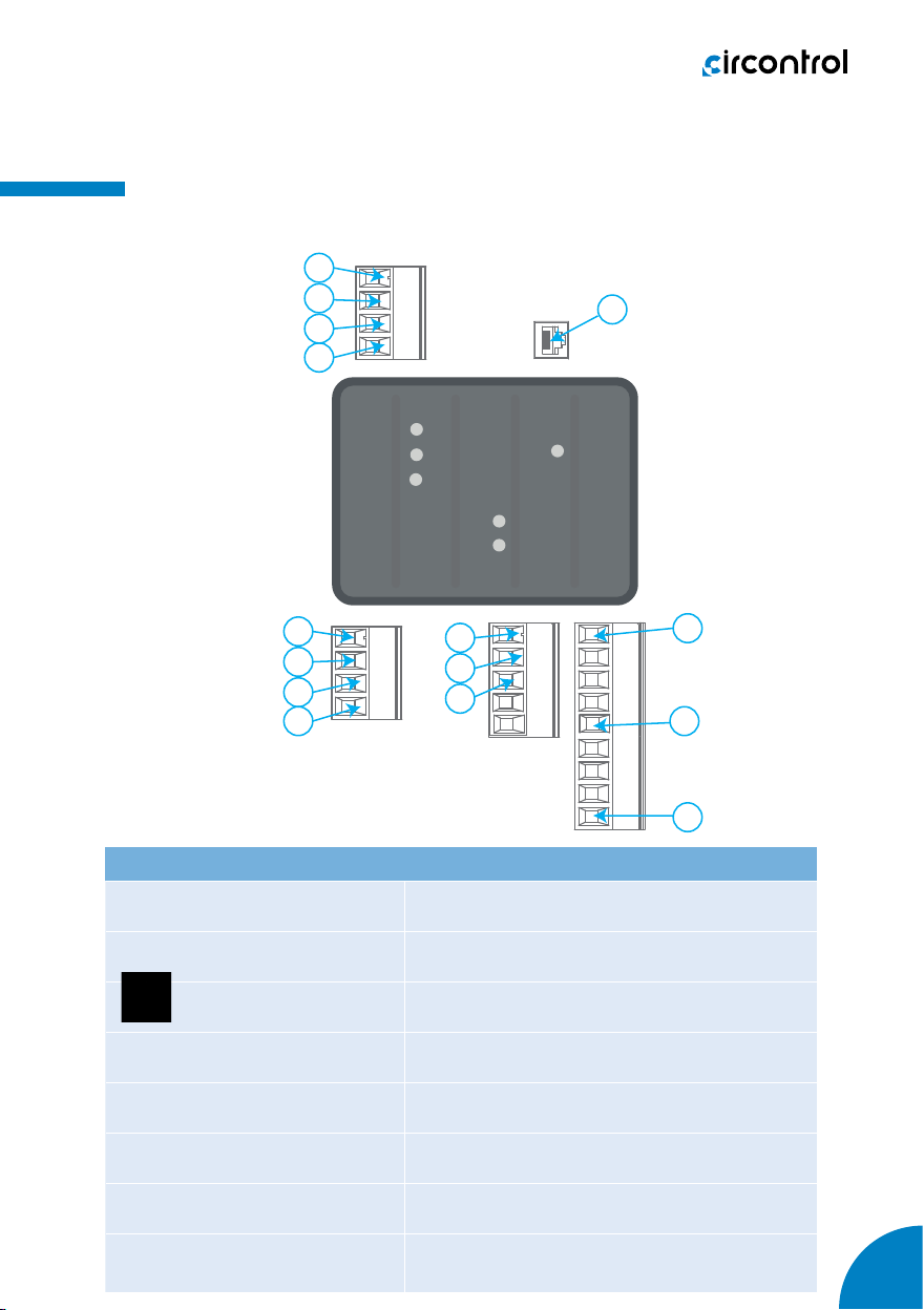
Overview
Genion One terminals
1. A1(+), Auxiliary power supply 9. V3, Voltage input
2. A2(-), Auxiliary power supply 10. N, Neutral voltage input
3. , Earth 11. N1, Neutral current input
4. B-, RS-485 connection 12. I3, EV recharging point current input
5. A+, RS-485 connection 13. I2, Photovoltaic generation current input
6. GND, RS-485 connection 14. I1, Mains current input
7. V1, Voltage input 15. Ethernet, Ethernet connection
8. V2, Voltage input
1
2
4
5
6
Genion One
7
8
9
10
11
12
13
14
15
3
11
12
13
14
15
1
2
3
5
4
6
7
8
9
10
Genion One

10
Genion One - Installation Manual
The equipment is installed on DIN rail.
4
The equipment must be connected to a power supply circuit protected
with gL (IEC 60269) or class M fuses, between 0.5 and 2 A. A circuit breaker
or equivalent device must be provided to disconnect the equipment from
the power supply.
With the equipment connected, you may have
access to parts that are dangerous to the touch via
the terminals or by opening of covers or removing
certain elements. The equipment should not be used
until it has been completely installed.
11
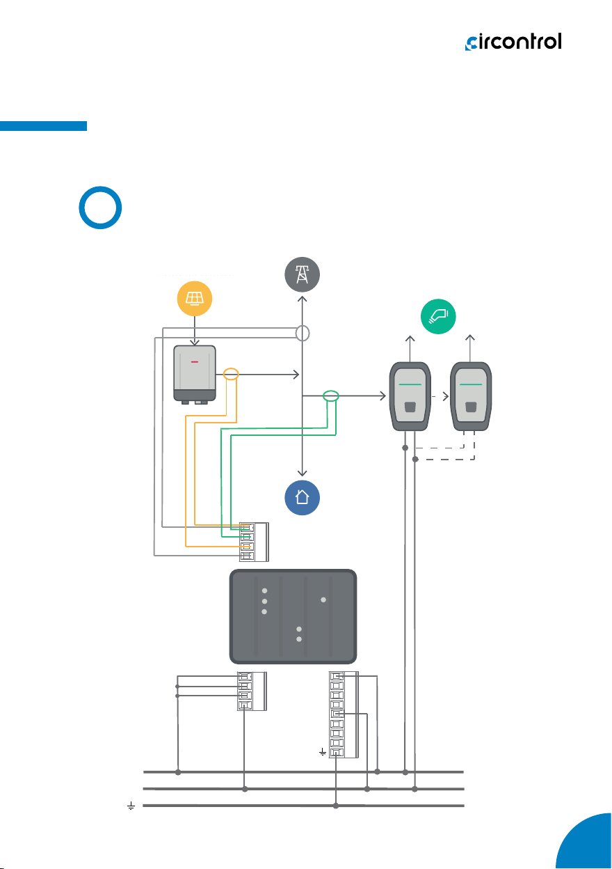
Equipment installation
Wiring diagram
A
L1
N
V1
V2
V3
NA2(-)
N1
I3
I2
I1
eHome Link
Genion One
Generación Fotovoltaica
Photovoltaic Generation Red Eléctrica
Mains Cargador VE
EV charger
A1(+)
Generación Fotovoltaica
Photovoltaic Generation Red Eléctrica
Mains
eHome Link
I1
I3
N1
I2
Genion One
N
L1
V1
V2
V3
N
A1(+)
A2(-)
Cargador VE
EV Charger

12
Genion One - Installation Manual
5
LED indicators
A
Genion One has 6 LED indicators that allow you to monitor the status of the
equipment at all times.
Power
RS-485
CPU
L1
L2
L3
L1
L2
L3
• Power. Equipment status:
LED Description
RS-485
Power on (blue)
Data transmission
On (green)
Data being received
LED Description
Power On (green)
Powered equipment
• RS-485. RS-485 communication status:

13
Operation
• CPU. CPU status:
LED Description
CPU Power on (blue)
CPU activated
• L1, L2, L3. Line status: cos φ: 1 ... 0.8
»L1. Status of the Mains Power line.
»L2. Status of the Photovoltaic Generation line.
»L3. Electric Vehicle (EV) charging point line status.
Q1Q2
Q3 Q4
+P
+Q
-Q
-P
cos 0.8
●
●
●
●
◒
◒
Standard Q1 Q2 Q3 Q4
CIRCONTROL ●
cos φ: 1 ... 0.8
◒
cos φ: 0.8 ... 0
●
cos φ: 0 ... -1
●
cos φ: 1 ... 0
●
cos φ: -1 ... -0.8
◒
cos φ: -0.8 ... 0
IEC 62053-23 ●
cos φ: 1 ... 0.8
◒
cos φ: 0.8 ... 0
●
cos φ: 0 ... -1
●
cos φ: 0 ... -1
●
cos φ: 1 ... 0.8
◒
cos φ: 0.8 ... 0
IEEE ●
cos φ: -1 ... -0.8
◒
cos φ: -0.8 ... 0
●
cos φ: 1 ... 0
●
cos φ: 0 ... -1
●
cos φ: 1 ... 0.8
◒
cos φ: 0.8 ... 0
○ LED off, ● LED on, ◒ LED blinking.

14
Genion One - Installation Manual
Reset
B
The unit has a Reset button to restore the factory settings. There are two
modes available:
• Soft Reset: If the button is pressed for 3 seconds, the unit will restore
the factory settings for the communication parameters.
• Hard Reset: If the button is pressed for 10 seconds, the unit will restore
the factory settings for all conguration parameters.
Genion One
Reset
Genion One
Reset

15
THIS PAGE HAS BEEN INTENTIONALLY LEFT BLANK
16
Genion One - Installation Manual
6
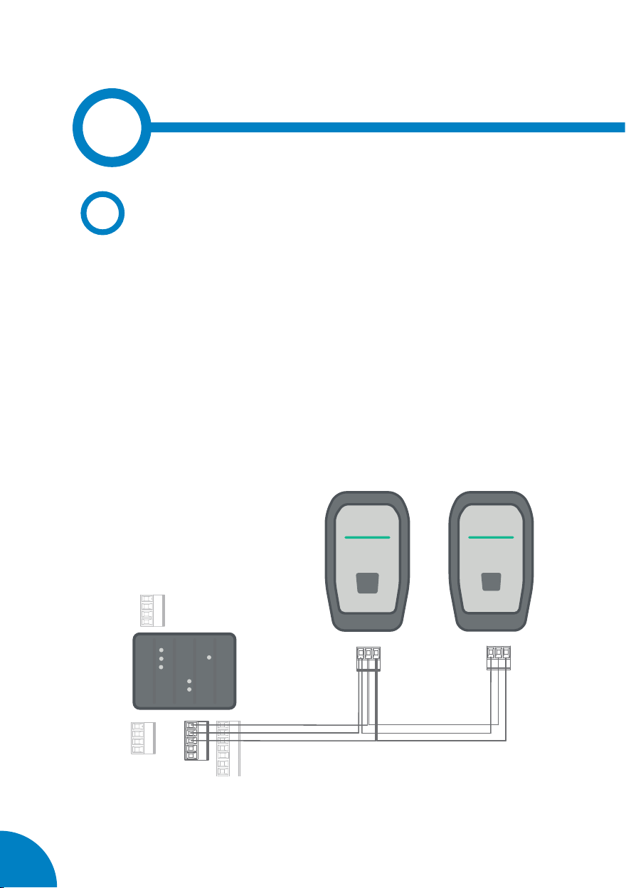
RS-485 communications
A
Genion One has an RS-485 communications port for communicating with
EV charging points.
The RS-485 cable should be composed of a twisted pair cable with a
shielding sheath (minimum 3 wires), with a maximum distance between
the Genion One and the satellite equipment of 1200 metres.
eHome Link eHome Link
Genion One
B-
A+
GND
B-A+ GND B-A+ GND
eHome Link eHome Link
Genion One
Table of contents
Other Circontrol Automobile Batteries Charger manuals


