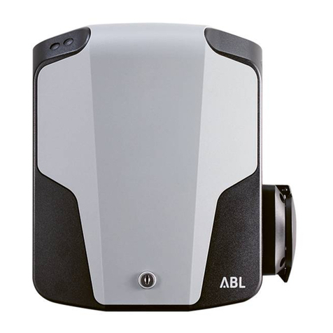
ABL eMH3 User manual

VERSION: EMH3-2016-10-28-UM ARTICLE NO. 0301590
Operating Manual
Wallbox
eMH3

ii
Contact
Manufacturer
ABL SURSUM
Bayerische Elektrozubehör GmbH & Co. KG
Albert-Büttner-Straße 11
91207 Lauf / Pegnitz
Germany
Phone +49 (0) 9123 188-0
Fax +49 (0) 9123 188-188
Web www.abl.de
Mail [email protected]
Customer
Support
Phone +49(0)9123 188-600
Email emobility[email protected]

iii
Contents
Contact . . . . . . . . . . . . . . . . . . . . . . ii
Important information . . . . . . . . . . . . . . . . . . . . . . 1
About this manual . . . . . . . . . . . . . . . . .1
Safety notices in this manual . . . . . . . . . . . . . 1
Safety notices on the device . . . . . . . . . . . . . 2
General safety information . . . . . . . . . . . . . .2
General product information . . . . . . . . . . . . . 3
User information . . . . . . . . . . . . . . . . . . 4
Introduction . . . . . . . . . . . . . . . . . . . . . . . . . . . 6
Introducing the product . . . . . . . . . . . . . . . 6
Unpacking and components included . . . . . . . . .7
Identifying your model variant . . . . . . . . . . . .7
Available accessories . . . . . . . . . . . . . . . . 9
Taking into operation and charging procedure . . . . . . . . 11
Safety information for taking the wallbox into
operation . . . . . . . . . . . . . . . . . . . . 12
Operating instructions . . . . . . . . . . . . . . . 12
Description of the RFID module . . . . . . . . . . . 13
Deactivating and reactivating of the charging
function via RFID . . . . . . . . . . . . . . . . . 14
Registering additional RFID cards . . . . . . . . . . 15
Resetting RFID cards . . . . . . . . . . . . . . . 15
Operating status (RFID module) . . . . . . . . . . . 16
Charging procedure . . . . . . . . . . . . . . . . 17

iv
Resolving errors . . . . . . . . . . . . . . . . . . . . . . . . 19
Error messages during the charging procedure . . . . 19
Error codes for RFID module operation . . . . . . . . 20
Disruptions to the operation of the charging station
and solutions . . . . . . . . . . . . . . . . . . 20
Checking the internal RCCBs . . . . . . . . . . . . 21
Taking the wallbox out of and back into operation . . . 22
Frequently asked questions . . . . . . . . . . . . 23
Appendix . . . . . . . . . . . . . . . . . . . . . . . . . . . 25
Technical specifications . . . . . . . . . . . . . . 25
Scale drawings and dimensions . . . . . . . . . . . 27
Guidelines & Norms . . . . . . . . . . . . . . . 28
CE certification and compliance declaration . . . . . . 29
Glossary & Definitions. . . . . . . . . . . . . . . 29
Trademarks . . . . . . . . . . . . . . . . . . . 30
Intellectual Property & Copyright . . . . . . . . . . 30
Disposal advice . . . . . . . . . . . . . . . . . 30

Important InformatIon
1
Important information
About this manual
This manual documents the steps and options necessary for set up and operation of
your ABL Wallbox. For quick and easy reference, certain sections of this manual are
specially formatted.
• Descriptions listing equally valid options (as is the case here) are indicated by bullet
points.
• Descriptions that describe performing a function are shown in the form of numerical
lists indicating the order of the individual working steps.
Please make sure you read this manual, as it contains important information for us-
ing the wallbox with your electric vehicle. Please especially follow all operational and
safety notices that are printed in this manual.
Keep this manual in a safe place for future reference. In case the wallbox is operated
by several users, the contents of this manual, and the safety notices in particular, must
in all cases be passed on to each individual user or made available to them.
All measurements in this manual are in millimeters. Where necessary, the scale is
indicated for different illustrations.
Please note that all technical details, specifications and design characteristics of the
product may be changed without prior notice.
Safety notices in this manual
In particular, the warnings and safety measures in this manual that are marked as fol-
lows must be adhered to. The symbols carry the following meanings:
DANGER!
Sections marked with this symbol draw attention to electrical voltages that
represent a danger to life and limb. Actions marked with this symbol must
not be carried out under any circumstances.
CAUTION!
Sections marked with this symbol draw attention to further hazards that
may lead to damage to the device itself or to other electric devices. Actions
marked with this symbol must be carried out with special care.

Important InformatIon
2
PLEASE NOTE:
Sections marked with this symbol draw attention to further important in-
formation and special features that are necessary for operating the device
successfully. Actions marked with this symbol should be carried out as
required.
Safety notices on the device
Further operational and safety notices are provided on the outside of the housing and
on the electronic components cover inside the wallbox. These symbols carry the fol-
lowing meanings:
WARNING!
Please ensure that you first read the operating manual (this document),
especially before you open the housing cover of your ABL Wallbox.
WARNING!
After opening the housing, dangerous electrical voltages may be present
inside the wallbox.
General safety information
Please pay attention to the following points:
• Read this manual carefully.
• Heed all warnings.
• Follow all instructions.
• The wallbox must be installed, connected and approved for operation according to
local regulations and conditions by a qualified specialist electrical contractor.
• Please ensure that a minimum distance of 50 cm to the wallbox is kept on all sides
after installation.
• Under no circumstances remove the protective cover for electronic components be-
hind the housing cover of the ABL Wallbox. Cleaning or maintenance of components
behind this cover is not necessary, and must under no circumstances be performed
by the user.
• The ABL Wallbox must only be operated with the housing cover closed and locked:
Before charging, ensure that the housing cover is closed and lock it using the trian-
gular key supplied.
• Only use accessories intended and sold for the device by ABL.
• Do not operate this wallbox in close vicinity to running water or water jets: However,
the ABL Wallbox is sufficiently protected against water splashes and sprays accord-
ing to the respective protection degrees.

Important InformatIon
3
• The ABL Wallbox must not be installed in areas subject to flooding.
• The ABL Wallbox must not be installed in explosive atmosphere areas (EX areas).
• The ABL Wallbox must not be covered with stickers or other objects or materials so
that sufficient air circulation is ensured at all times.
• No liquids, or objects or receptacles containing liquids must be placed on the hous-
ing.
• Please note that operating a radio transmitter in the immediate vicinity (< 20 cm) of
the wallbox may lead to malfunctions and should therefore be avoided.
• This device is not intended to be used by persons with limited physical, sensory or
mental abilities (including children) and/or lacking knowledge, unless they are super-
vised by someone responsible for their safety or have received instructions from
such a person on how to use the device.
• Children must be supervised so that they do not play with the device.
• Please note that the ABL Wallbox may be installed and operated at elevations of
max. 2,000 meters AMSL (above mean sea level).
General product information
This ABL Wallbox represents the current state of technology and complies with all cur-
rent technical safety requirements, guidelines and standards. The safety information
provided in this manual serves to ensure the proper and safe operation of the device.
Disregard of or actions contrary to the safety information and instructions contained in
this manual may lead to electric shock, fire and/or severe injury. Malfunctions affecting
the safety of persons, connected electric devices or the device itself must be repaired
by a qualified electrical contractor.
Should a malfunction occur with the wallbox, please always contact the company that
carried out the installation first. If the malfunction can still not be resolved, please con-
tact your local ABL technical support.
Always contact your local ABL technical support if:
• the housing has been damaged mechanically,
• the housing cover has been removed or can no longer be closed or locked,
• sufficient protection against splashing water and/or foreign objects is obviously no
longer evident,
• there is functional or visible damage to the charging socket or external charging
cable
• or the wallbox does not function properly or has been otherwise damaged.

Important InformatIon
4
DANGER!
Should you detect damage to the housing, charging socket or charging
cable, you must take the wallbox out of operation immediately via the
upstream fuse(s) in your domestic power distribution box and the internal
residual current circuit breaker: No further use of the wallbox is permitted
in this case! Please contact your local ABL technical support!
User information
To operate your wallbox, please note these instructions:
• The device must always be connected to the protective earth conductor of your
electricity supply. The protective earth connection will be made and checked by the
installing contractor. After installation, only qualified specialist electrical contractors
may make changes.
• The wallbox should not be installed in areas of high pedestrian traffic. Installation
along thoroughfares and marked escape routes should be especially avoided.
• When there is no charging procedure under way, the charging cable should always
be unplugged and stored to avoid trip hazards.
• Ensure that the rated voltage and rated current of the device comply with the pa-
rameters of your local electricity grid and that the rated output is not exceeded dur-
ing the charging procedure.
• At all times comply with local safety regulations for the country in which you operate
the wallbox.
• To disconnect the wallbox completely from the power grid, the power supply must
be interrupted using the upstream fuse(s) and the internal residual current circuit
breaker (RCCB).
• Never operate the wallbox in a confined space. In particular, you must ensure that
the vehicle can be parked at a suitable distance from the wallbox and connected
without any strain on the charging cable.
• A parking spot for the vehicle must be planned for in the area in front of the wallbox.
The distance between vehicle and wallbox should be at least 50 cm and no more
than 5 m.
• Make sure that the cover of the wallbox housing is always closed and locked when
in use. Keep the triangular key for unlocking the door in a place that is only acces-
sible to authorized users.
• Under no circumstances remove the protective cover for electronic components
located behind the housing cover of the wallbox.

Important InformatIon
5
• You must not under any circumstances make any changes to the housing or the
internal wiring of the wallbox: Any disregard of this instruction represents a safety
risk, fundamentally breaches the guarantee provisions and may void the warranty
with immediate effect.
• Only have qualified, specialist personnel install and/or repair the device. No parts to
be maintained by the user are located inside the device.

IntroductIon
6
Introduction
Thank you for choosing this wallbox to charge your electric vehicle! With this ABL Wall-
box, you have selected an innovative and future proof solution.
eMobility helps to save natural resources and protect the environment sustainably.
The ABL Wallbox combines progressive and pleasing design with intuitive function-
ality: According to their requirements, users may select from models with charging
socket or fixed charging cable, which are designed for domestic and also for semi-
public applications.
ABL Wallboxes are manufactured in Germany and comply with the regulations and
norms for the charging of electric vehicles applicable throughout Europe according
to IEC 61851-1, Mode 3. Please refer also to the section on “Wallboxes 3W2214,
3W2217 and 3W4401” on page 28.
Introducing the product
Your ABL Wallbox allows you to comfortably and safely charge electric vehicles accord-
ing to IEC 61851-1 Mode 3 and is designed for the shortest possible charging times.
We place the highest value on user safety in all our products. For this purpose, your
wallbox offers integrated DC fault current detection which, in combination with an
internal type A residual current circuit breaker (residual current device, called RCCB in
the following) and the protective measures of your electric vehicle effectively protects
from short circuit, electric shock and other operational hazards.
The wallbox is especially easy to operate during everyday use: LED lights on the hous-
ing cover allow you to check the current operating status at any time. Should a mal-
function occur, you can identify the cause by its specific LED error code without hav-
ing to open the housing. After being taken into operation by a specialist contractor, the
ABL Wallbox is ready for charging at any time. For some model variants each charging
process must be separately authorized via the integrated RFID module, provided this
function was activated during installation.
A common characteristic of all wallboxes is the attractively designed housing, which
effectively protects the internal electric circuits against environmental influences and
unauthorized access. In principle, all model variants of the wallbox must be installed
and taken into operation by a qualified electrical contractor. Please contact your local
ABL partner with any queries you may have.

IntroductIon
7
Unpacking and components included
Your ABL Wallbox is delivered in an extremely sturdy box, including a range of acces-
sory components required for proper operation. Therefore, please check immediately
after unpacking whether the following components are included:
COMPONENT QUANTITY DESCRIPTION
Wallbox 1 Wallbox, consisting of plastic housing with lockable
cover and separate mounting plate.
Quick start guide 1 Quick start guide including safety notices in printed
form
Installation kit 1
Set of fixings for wall mounting, consisting of 2 x 4
screws as well as matching wall plugs, triangular key,
strain relief including screws (2 pcs), sealing grom-
mets for openings at the back of the housing (3 pcs)
Should one or more components be missing after unpacking, please contact your local
ABL distributor immediately:
Identifying your model variant
The ABL Wallbox series comprises several model variants, which are mechanically and
electrically adapted to different usage profiles. A product sticker with the specific ABL
product identification number is located on the internal electronic components cover.
Please check the product sticker to ensure that the model variant you have installed is
the one described in this manual.
The model code (3WXXXX) as well as the
power supply ratings (voltage, frequency,
current) indicated below it are especially
relevant for proper identification.
The following wallboxes are described in this manual:
MODEL NUMBER GRID CONNECTION MODEL VARIANT
3W2205
230 / 400 V
50 Hz 32 A
Single charging station according to
IEC 62196-2 Type 2; integrated, factory
deactivated RFID module for access
control; internal Type A RCCB; internal
DC fault current detection; charging
output up to 22 kW
3W440100001
2016-08-17
3W4401
~230/400V 50Hz 2 x 32A
IP54
IEC 61851-1
IEC 61439-7 ACSEV
MADE IN GERMANY
ABL SURSUM Bayrische Elektrozubehör GmbH & Co. KG
3W440100001

IntroductIon
8
MODEL NUMBER GRID CONNECTION MODEL VARIANT
3W2207
230 / 400 V
50 Hz 32 A
Single charging station with integrated
charging socket according to IEC
62196-2 Type 2 with locking mecha-
nism for separately available charging
cable (Type 2 to Type 2 or Type 2 to
Type 1); integrated, factory deacti-
vated RFID module for access control;
internal
Type A RCCB; internal DC fault
current detection; charging output up
to 22 kW
3W2209
230 / 400 V
50 Hz 32 A
Single charging station with integrated
charging socket according to IEC
62196-2 Type 2 with shutter and lock-
ing mechanism for separately available
charging cable (Type 2 to Type 2 or
Type 2 to Type 1); integrated, factory
deactivated RFID module for access
control; internal Type A RCCB; internal
DC fault current detection; charging
output up to 22 kW
3W2214
230 / 400 V
50 Hz 32 A
Twin charging station with two inte-
grated charging sockets according to
IEC 62196-2 Type 2 with locking mech-
anism for separately available charging
cable (Type 2 to Type 2 or Type 2 to
Type 1); integrated, factory deacti-
vated RFID module for access control;
internal Type A RCCB; internal DC fault
current detection; internal load man-
agement for charging outputs of up to
2 x 11 kW or 1 x 22 kW
3W2217
230 / 400 V
50 Hz 32 A
Twin charging station with two inte-
grated charging sockets according to
IEC 62196-2 Type 2 with shutter and
locking mechanism for separately
available charging cable (Type 2 to
Type 2 or Type 2 to Type 1); integrated,
factory deactivated RFID module for
access control; internal Type A RCCB;
internal DC fault current detection;
internal load management for charging
outputs of up to 2 x 11 kW or 1 x 22
kW

IntroductIon
9
MODEL NUMBER GRID CONNECTION MODEL VARIANT
3W4401
230 / 400 V 50 Hz
2 x 32 A
Twin charging station with two inte-
grated charging sockets according to
IEC 62196-2 Type 2 with locking mech-
anism for separately available charging
cable (Type 2 to Type 2 or Type 2 to
Type 1); integrated, factory deacti-
vated RFID module for access control;
internal
Type A RCCB; internal DC fault
current detection; charging output of
up to 2 x 22 kW
WARNING!
The information and technical specifications contained in this manual relate
exclusively to the above-mentioned model variants and must not be trans-
ferred to other wallbox models. These variants are delivered with specific
instruction manuals where necessary.
Available accessories
ABL sells additional accessories for your eMH3 Wallbox. For the models of the eMH3
series, the following components are available:
DESIGNATION ARTICLE NO. QUANTITY
Type 2 charging cable
(model variants 3W2214, 3W2217 and
3W4401) for connection with all eMH3
wallboxes and vehicles with charging
sockets according to IEC 62196-2 Type
2, 32 A 240 / 415 V AC and IP44 splash
protection rating
Length: approx. 4 meters
LAK32A3 1
Adapter cable Type 2 to Type 1
(model variants 3W2214, 3W2217 and
3W4401) for connection to all eMH3
wallboxes with charging sockets accord-
ing to IEC 62196-2 Type 2, with charg-
ing connector according to IEC 62196-2
Type 1, 32 A 230 V AC, and IP44 splash
protection rating
Length: approx. 4 meters
LAKK2K1 1

IntroductIon
10
DESIGNATION ARTICLE NO. QUANTITY
Mounting pole
for installing all eMH3 wallbox models
Dimensions: 1650 x 400 x 150 mm
Weight: 21,500 g
(does not include the wallbox pictured)
STEMH301
Please contact your local distributor if you require additional information about these
components or would like to place an order.
CAUTION!
Please note that the do-it-yourself installation of accessory components
is not permitted: Please contact a qualified contractor or arrange installa-
tion with your local distributor.
Please also visit our website at ...
www.abl.de
You will find further information about our products and our entire range there.

takIng Into operatIon and chargIng procedure
11
Taking into operation and charging procedure
The mechanical and electrical installation of the ABL Wallbox model variant described
in this manual must always be carried out by qualified specialist personnel: Prepara-
tion of the domestic power supply, and electrical connection to your domestic power
supply in particular, must be carried out by a qualified electrical contractor, and subse-
quently inspected and approved as part of the process of taking the device into opera-
tion. Please contact a specialist electrical contractor or your local ABL partner, who will
be pleased to assist you with any questions regarding the installation and operation of
your wallbox.
Installation itself is described in the a separate installation manual. That manual con-
tains important information regarding mechanical and electrical installation as well as
regarding the subsequent functional inspection, approval and taking into operation of
the wallbox. It is advisable that you are present when the device is taken into opera-
tion for the first time by a qualified electric contractor to ensure that your are able to
easily carry out charging procedures with your ABL Wallbox.
The current operating status of the wallbox is indicated by the color LEDs in the lower
part of the housing cover. Each LED may ...
...
be illuminated
(continuous ON)
... flash ...
be extinguished
(continuous OFF).
You can find further information about operating states on the following pages.
Your wallbox is ready for use immediately after mechanical and electrical installation
have been completed. While the 3W2205 model variant has a fixed charging cable
with a Type 2 charging connector, the 3W2207 and 3W2209 model variants come with
one, the 3W2214, 3W2217 and 3W4401 with two IEC 62196-2 Type 2 charging sock-
ets each. To connect your vehicle to model variants with charging socket(s), you will
need the separately available charging cable. To provide a high level of flexibility, ABL
has two different cables on offer for this purpose:
MODEL NUMBER DESCRIPTION MAXIMUM
OUTPUT
LAK32A3
Type 2 charging cable for connecting all eMH3
wallboxes and vehicles with charging socket in
acc. with IEC 62196-2 Type 2
22 kW
LAKK2K1
Adapter cable Type 2 to Type 1 for connection
to all eMH3 wallboxes with charging socket in
acc. with IEC 62196-2 Type 2, with charging
connector according to IEC 62196-2 Type 1
7.4 kW

takIng Into operatIon and chargIng procedure
12
The charging connector or charging sockets of the eMH3
have three current-carrying contacts, a neutral conductor, a
PE protective earth conductor as well as two signaling con-
tacts (Control Pilot and Proximity Pilot), which ensure a se-
cure connection and therefore the safe operation of the
wallbox.
Charging sockets have an electromechanical locking mech-
anism that secures the charg-
ing plug in place as soon as the
charging cable is connected to
both the wallbox and the vehi-
cle. As long as the plug of the
external charging cable is not locked into place in the charg-
ing socket of the eMH3, the charging process cannot be
initiated and no voltage will be applied from the socket to
the charging cable via the current-carrying contacts.
Safety information for taking the wallbox into operation
Before you take the eMH3 wallbox into operation, you must observe the following
safety notices:
• Ensure that the eMH3 is connected to the domestic power supply according to the
instructions in this manual and the separately available installation manual.
• Ensure that the eMH3 is protected separately in your domestic power distribution
box by suitable miniature circuit breakers (MCB, C characteristic).
• Ensure that any integrated upstream residual current circuit breakers (RCCB, if pres-
ent) in the wallbox are switched on.
• Ensure that the eMH3 has been mechanically installed according to the instructions
in this manual: Check especially that access to the wallbox is unobstructed, that it is
not exposed to direct sunlight or rain and that the electric vehicle can be connected
without any strain or other encumbrance on the charging cable.
• Ensure that the housing cover of the eMH3 is always closed and locked during op-
eration.
• Ensure that the integrated or separately available charging cable is not twisted and
check that cable, connector and housing do not show any observable damage.
Operating instructions
• The separately available charging cables (all model variants except 3W2205) are ca.
4 meters long to offer a flexible connection between wallbox and vehicle. In prac-
tice, it is advisable to remove the charging cable after each charging process.
CPPP
L1
N
CP
N
L2
PE
L3

takIng Into operatIon and chargIng procedure
13
• If you want to store your cable on the wallbox you can wrap it around the eMH3: This
way it is always close at hand.
• Although the cable and connector are designed to withstand high mechanical stress-
es, you should not drive your vehicle over the cable and/or the connector.
• Also ensure that the cables are not kinked at the charging socket and that there is
no excessive strain on the cable and/or the housing.
DANGER!
If the cables, the charging connectors and/or the housing have suffered
mechanical damage or show visible deformities, you must under no cir-
cumstances continue to operate the wallbox. Please contact your local
distributor from whom you have purchased the wallbox.
Description of the RFID module
The factory setting for the eMH3 RFID module is 'deactivated', but the module can be
activated during initial installation or at a later time by a qualified specialist. For more
information, see the installation manual for the eMH3.
After activation, the RFID module principally serves to identify the user and therefore
to restrict or allow access to the charging procedure for a defined user group. Authen-
tication is conducted via RFID compliant transponders and/or RFID access cards in
MIFARE Ultralight® format. The different types of cards are as follows:
• TEACH-In tag card
This card serves to program ID tag cards using the teach-in process. In addition, the
wallbox can be deactivated and then reactivated for operation using this card. One
Teach-In card is supplied with the eMH3.
• ID tag card
This card serves to identify the user and authorize the charging procedure. Five ID
tag cards are included.
PLEASE NOTE:
The RFID module is factory pre-set to theTeach-In and ID tag cards included.
Therefore,pleasekeeptheTeach-Intagcardinasafeplace.IftheTeach-Incard
is lost, please contact your local distributor.
Additional ID tag cards can be ordered by the user at any time and regis-
tered using the module.
Programming the ID tag cards, authorizing the charging proce-
dure and deactivating/reactivating the charging function is car-
ried out via the RFID module located in the upper part of the
housing cover. During programming, registration and opera-
tion, status and feedback information from the RFID module is
displayed by one green and one blue LED.

takIng Into operatIon and chargIng procedure
14
In the TWIN models 3W2214 and 3W2217, the RFID module controls basic load man-
agement, even when access control has not been activated. Should both charging
sockets be in use for charging at the same time, load management distributes the
maximum available current equally to both charging points. When only one charging
socket is in use, the maximum available current is allocated to this charge point.
In addition, the RFID module allows you to deactivate or reactivate the charging func-
tion in case you want to take the wallbox temporarily out of operation.
Deactivating and reactivating of the charging function via RFID
The charging function of the eMH3 can be deactivated and reactivated independently
of the access control function: The factory preset for the charging function is always
'activated'. Proceed as follows to deactivate the charging function:
1. Check the status of the eMH3 via the LEDs on the
lower part of the housing cover. When the wallbox
is ready for operation, the blue LED will flash
every 5 seconds.
Blue flashes every 5 seconds
2. Check the status of the RFID module via the LEDs
located on the upper part of the housing cover:
When the wallbox is ready for operation, the green
LED flashes (
factory setting:
access control dis-
abled) or the blue LED (access control enabled)
flash every 5 seconds.
Green LED flashes every 5 sec., blue LED
is OFF
(access control disabled)
Green LED is OFF, blue LED flashes every
5 sec., (access control enabled)
3. Place the Teach-In tag card in front of the RFID
module: The blue LED is ON.
4. When the green LED flashes twice, remove the
Teach-in card.
Green LED flashes twice, blue LED is OFF
5. The RFID module will now restart and the charg-
ing function is now deactivated. During continuing
operation, both the green and the blue LED will
now remain ON.
Green and blue are ON continuously
(charging function deactivated)
For model variants with charging socket, any time a charging connector is plugged into
the vehicle socket, it is locked, but no charging takes place.
Proceed as follows to reactivate the charging function of the eMH3:
1. Check the status of the RFID module via the LEDs
located on the upper part of the housing cover:
When the charging function is blocked, both the
green and blue LED will be ON continuously.
Green and blue are ON continuously
(charging function deactivated)

takIng Into operatIon and chargIng procedure
15
2. Place the Teach-In tag card in front of the RFID
module: The blue LED is ON.
3. When the green LED flashes twice, remove the
Teach-in card.
Green LED flashes twice, blue LED is OFF
Now the RFID module restarts. After restart, the charging function is reactivated.
Registering additional RFID cards
If the RFID module has been activated during or after installation (see installation
manual), you can register additional ID tag cards for your eMH3 wallbox in order to
extend the user group: You can obtain suitable MIFARE Ultralight® cards from your
local distributor. Proceed as follows to register an RFID access card on your eMH3:
1. Check the status of the eMH3 via the LEDs on
the lower part of the housing cover. When the
wallbox is ready for operation, the blue LED
will flash every 5 seconds.
Blue flashes every 5 seconds
2. Check the status of the RFID module via the
LEDs located on the upper part of the housing
cover: When access control has been activated,
the blue LED will flash every 5 seconds.
Green LED is OFF, blue LED flashes every 5
sec., (access control enabled)
3. Place the Teach-In tag card in front of the RFID
module: Remove the card when the blue LED is
ON. Green LED is OFF, blue LED is ON
4. Now, place a not previously registered ID tag card
in front of the RFID module within 10 seconds:
The green LED now flashes once. Green LED flashes once, blue LED is OFF
The ID tag card is now registered with the RFID module. Repeat this process to reg-
ister more ID tag cards with the RFID module.
WARNING!
If the ID tag card is already registered or no further cards can be registered
in the wallbox memory, both the green and the blue LED will flash continu-
ously.
Resetting RFID cards
If the RFID module has been activated during or after installation (see installation
manual), it may become necessary to reset RFID tag cards registered with the RFID
module (e.g. in order to program the RFID module with new access data using a dif-
ferent Teach-In card.

takIng Into operatIon and chargIng procedure
16
Proceed as follows to initialize the registration of cards on the RFID Module:
1. Separate the eMH3 from the electricity supply by switching the internal RCCB or
the upstream MCB in the domestic installation to the 0position.
2. Place a Teach-In card in front of the RFID module and then switch the internal
RCCB or the upstream MCB back to the Iposition.
3. The blue LED on the RFID module will now be
ON continuously.
Green LED is OFF, blue LED is ON
4. Remove the Teach-In tag card when the green
LED flashes three times.
Green LED flashes three times, blue LED is
OFF
The internal memory is now erased and ID tag cards can be re-registered.
Operating status (RFID module)
If the RFID module has been activated during or after installation, the two LED indica-
tors located in the upper part of the housing cover of the eMH3 will show the current
operating status of the RFID module. During normal operation, the following operating
states are shown:
DESCRIPTION
The RFID module is ready for use, a charging process may
be requested at any time using an authorized transponder
(access card)
Green LED flashes every 5
seconds, blue LED is OFF
The RFID module has read the transponder data and initiated
authentication
Green LED flashes once,
blue LED is OFF
Authentication of the transponder was successful, access to
the charging process is being granted.
Green LED is ON for one
second, blue LED is OFF
Authentication of the transponder was NOT successful, ac-
cess to the charging process is NOT being granted.
Green LED is OFF, blue LED is
ON for one second
PLEASE NOTE:
Should the RFID module of the eMH3 refuse authentication of the charg-
ing process, this indicates that the ID tag card is not registered: Please
also refer to section”Resetting RFID cards” on page 15.
Other manuals for eMH3
5
Table of contents
Other ABL Automobile Batteries Charger manuals
Popular Automobile Batteries Charger manuals by other brands

DeWalt
DeWalt DXPAEV2000 instruction manual

Taramps Electronics
Taramps Electronics PRO CHARGER 30A instruction manual

ULTIMATE SPEED
ULTIMATE SPEED ULG 3.8 B1 operating instructions

Charge Amps
Charge Amps Ray Type 2 product manual

FRONIUS
FRONIUS Wattpilot Home 11 J 2.0 quick start guide

Sony
Sony DCC L50 operating instructions