Redarc BCDC1212T User manual

Multi-stage 12V Input Current Limited
In-vehicle Battery Charger
BCDC1212T

2
THE BCDC1212T
The BCDC1212T In-vehicle Battery Charger features technology designed to charge your auxiliary
batteries to 100%, regardless of their type or size.
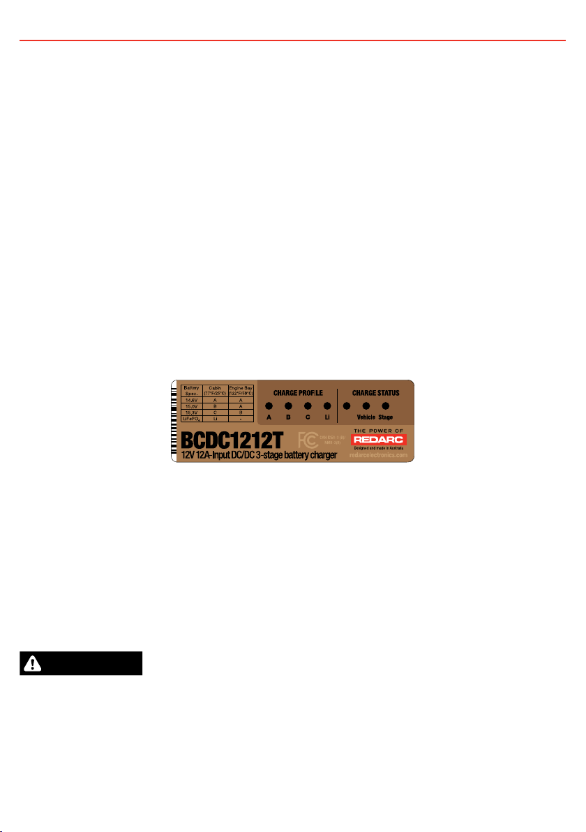
The In-vehicle Battery Charger is suitable for all common types of automotive lead acid batteries and
LiFePO4lithium type batteries.
WARNING AND SAFETY INSTRUCTIONS
SAVE THESE INSTRUCTIONS - THIS MANUAL CONTAINS
IMPORTANT SAFETY INSTRUCTIONS FOR THE BCDC1212T
BATTERY CHARGER.
DO NOT OPERATE THE BATTERY CHARGER UNLESS YOU HAVE
READ AND UNDERSTOOD THIS MANUAL AND THE CHARGER
IS INSTALLED AS PER THESE INSTALLATION INSTRUCTIONS.
REDARC RECOMMENDS THAT THE CHARGER BE INSTALLED
BY A SUITABLY QUALIFIED PERSON.
WARNING
RISK OF EXPLOSIVE GASES:
WORKING IN VICINITY OF A LEAD-ACID BATTERY IS
DANGEROUS. BATTERIES GENERATE EXPLOSIVE GASES
DURING NORMAL OPERATION. FOR THIS REASON, IT IS OF
UTMOST IMPORTANCE THAT YOU FOLLOW THE INSTRUCTIONS
WHEN INSTALLING AND USING THE CHARGER.
CAUTION
1. The Battery Charger should not be used by persons
(including children) with reduced physical, sensory or mental
capabilities, or lack of experience and knowledge, unless
they are supervised or have been instructed on how to
use the appliance by a person responsible for their safety.
Children should be supervised to ensure that they do not
play with the Battery Charger.
2. Do NOT alter or disassemble the Battery Charger under
any circumstances. All faulty units must be returned to
REDARC for repair. Incorrect handling or reassembly may
result in a risk of electric shock or fire and may void the unit
warranty.
3. Only use the Battery Charger for charging Standard
Automotive Lead Acid, Calcium Content, Gel, AGM, SLI
(Starting Lighting Ignition), Deep Cycle or Lithium Iron
Phosphate (LiFePO4) type 12V batteries.
4. Check the manufacturer’s data for your battery and ensure
that the ‘Maximum’ voltage of the profile you select does
not exceed the manufacturer’s recommended maximum
charging voltage. If the ‘Maximum’ voltage is too high for
your battery type, please select another charging profile.
5. Check the manufacturer’s data for your battery and ensure
that the ‘Continuous Current Rating’ of the charger does
not exceed the manufacturer’s recommended maximum
charging current.
6. When using the Battery Charger to charge a Lithium Iron
Phosphate (LiFePO4) battery, only batteries that feature an
inbuilt battery management system featuring inbuilt under
and over voltage protection and cell balancing are suitable.
7. The Battery Charger is not intended to supply power to a low
voltage electrical system other than to charge a battery.
8. Cable and fuse sizes are specified by various codes and
standards which depend on the type of vehicle the Battery
Charger is installed into. Selecting the wrong cable or fuse
size could result in harm to the installer or user and/or
damage to the Battery Charger or other equipment installed
in the system. The installer is responsible for ensuring that
the correct cable and fuse sizes are used when installing
this Battery Charger.
9. NEVER smoke or allow a spark or flame in the vicinity of
battery or engine. This may cause the battery to explode.
10. In applications where the BCDC1212T draws power through
the vehicle’s and trailer’s towing harnesses and connectors,
the harnesses wiring gauge, connectors and fuse current
ratings and fuse type should be checked by a suitably
qualified person to ensure that it is adequately rated for
safe and reliable operation and that the vehicle’s fuse is
appropriately rated and located to protect the wiring in the
event of a fault, including short circuits.
PERSONAL SAFETY PRECAUTIONS
11. To assist with the safe operation and use of the Battery
Charger when connected to the battery:
• Wear complete eye protection and clothing protection.
Avoid touching eyes while working near a battery.
• If battery acid contacts your skin or clothing, remove the
affected clothing and wash the affected area of your skin
immediately with soap and water. If battery acid enters
your eye, immediately flood the eye with running cold
water for at least 10 minutes and seek medical assistance
immediately.
Design and specifications are subject to change without notice | Copyright © 2020 REDARC Electronics Pty Ltd. All rights reserved. | REDARC®, THE POWER OF REDARC®,
and BCDC™ are trademarks of Redarc Electronics Pty Ltd.

3
SPECIFICATIONS
Part Number BCDC1212T
Continuous Input Current Rating 12A
Fuse Rating (Input / Output) 15A to 23A / 30A (Not supplied)
Vehicle Input Voltage Range* 9 to 32V
Nominal System Voltage 12V 24V
Max. Rated Output Current 11A 20A
Nominal Output Power 147W 294W
Output Battery Type Standard Lead Acid, Calcium content, Gel, AGM or LiFePO4type only
Charging Profile A B C Li
– Maximum Voltage* (refer to section 1.2) 14.6V 15.0V 15.3V 14.5V
– Float Voltage* 13.3V 13.6V
No Load Current <100mA
Standby Current <8mA
Minimum O/P Battery Volts 0.1V
Operating Temperature 5°F to 175°F / −15°C to 80°C
Charging Temperature
A, B & C – Output Batt. > 10.5V 5°F to +176°F / −15°C to +80°C
A, B & C – Output Batt. < 10.5V 32°F to +176°F / 0°C to +80°C
LiFePO4Batteries 32°F to +176°F / 0°C to +80°C
Weight 30oz / 850g
Dimensions 6.5"×4.7"×1.5" / 165×120×37mm
Warranty 2 years
EMC Compliance RCM, FCC, ICES
* Voltages Specified are ±100mV
CONTENTS
THE BCDC1212T 2
WARNING AND SAFETY INSTRUCTIONS 2
SPECIFICATIONS 3
1 PRODUCT FUNCTION 4
1.1 Display Panel 4
1.2 Charge Profile LEDs 4
1.3 Charge Status LEDs 5
1.3.1 Vehicle LED 5
1.3.2 Stage LED 5
1.3.3 Optional External LED 6
1.3.4 Charging Process 6
1.4 Turn On/Off Thresholds 7
1.5 Error Codes 7
1.6 Battery Test Mode 8
2 INSTALLATION 8
2.1 Install Location 8
2.2 Charge Profile Selection (ORANGE Wire) 9
2.3 Input Trigger Settings (BLUE Wire) 10
2.4 Cable sizing 10
2.5 Wiring 11
2.6 Fusing 11
2.7 Typical Setup 12
3 TROUBLESHOOTING 13
4 CHECKING THE PRODUCT SERIAL
NUMBER 13
5 FCC DECLARATION 14
6 FREQUENTLY ASKED QUESTIONS 14
7 TWO YEAR PRODUCT WARRANTY —
NORTH AMERICA 15

4
1 PRODUCT FUNCTION
The BCDC1212T is specifically designed for, but not limited to, applications where the input current
required to charge a trailer mounted auxiliary battery is drawn through the vehicle’s towing harnesses
and connectors. It limits the input current drawn to 12A which provides for safe and reliable operation
when using towing harnesses, fuses and connectors that are suitably rated without the need to install
additional cables and connectors between the start battery / alternator and the BCDC1212T / auxiliary
battery.
The BCDC1212T is a three-stage, 12V DC-DC battery charger that operates from an alternator input of
12V or 24V. The input voltage to the BCDC1212T can be above, below or equal to the output voltage
making it ideal for charging an auxiliary 12V battery where the distance from the start battery or
alternator may cause a significant voltage drop. When connected to a 12V alternator the BCDC1212T will
typically provide peak boost currents of 11A, and 20A when connected to a 24V alternator (the peak
boost current however also depends on alternator voltage and input cable voltage drop).
The BCDC1212T isolates the start battery from the auxiliary battery, to avoid over-discharging the start
battery.
1.1 Display Panel
The front panel features 7 LEDs to display the charge profile and charge status.
FIGURE 1.1.1: The BCDC1212T Front Panel
1.2 Charge Profile LEDs
The In-vehicle Battery Charger features 4 different charging profiles designed to suit your battery’s
charging requirements. It is recommended to refer to the charging specifications stated by the battery
manufacturer and the installation temperature chart below (Figure 1.2.1) before selecting the profile for
your installation.
The selected Charge Profile LED will be on solid when the unit is ON and charging. A flashing profile LED
indicates that the unit is in standby mode and NOT charging.
CAUTION
Check the manufacturer’s data for your battery and ensure that the ‘Maximum’ voltage of the profile you
select does not exceed the manufacturer’s recommended maximum charging voltage. If the ‘Maximum’
voltage is too high for your battery type, please select another charging profile.

5
1 PRODUCT FUNCTION
AUXILIARY BATTERY LOCATION
MAXIMUM BATTERY
VOLTAGE SPECIFICATION CABIN INSTALL 25
75 F ENGINE BAY
INSTALL
50 +
1
20 F+
14.6 A A
15.0 B A
15.3 C B
14.5 (LiFePO4) Li Not Recommended
FIGURE 1.2.1: Charge Profile Selection
1.3 Charge Status LEDs
The Charge Status LEDs indicate to the user which inputs are available and what stage of the charge
process the unit is currently in.
1.3.1 Vehicle LED
The Vehicle LED will be ON when the input is available and in use and OFF when the input is not available
or not in use.
1.3.2 Stage LED
The Stage LED indicates the charge profile stage. With any profile selected the charger will output a
3-Stage charging profile consisting of Boost, Absorption and Float Stages.
Figure 1.3.2.1 outlines the LED sequences which indicate these stages and figure 1.3.4.1 explains the
Charging Process.
LED SEQUENCE PROFILE STAGE (LITHIUM)
Continuous
OFF / No Output
Continuous
Boost (Constant Current)
2 seconds
Absorption (Constant Voltage)
2 seconds
Float
FIGURE 1.3.2.1: Stage LED Sequences

6
1 PRODUCT FUNCTION
1.3.3 Optional External LED
An option external LED (see Figures 2.7.1 and 2.7.2) can be used to provide charge status and error
feedback away from the BCDC unit and is voltage limited to 9V and current limited to 6mA. A serial
resistor and LED should be selected to these specifications. A basic 3V LED can be wired as shown.
If used, this external LED is either OFF (BCDC not charging), ON (BCDC charging) or FLASHING (see error
codes in Section 1.5 Error Codes). A “12V” LED (3V with integrated resistor) will not operate correctly if
installed.
1.3.4 Charging Process
Voltage
FloatAbsorptionBoost
Current
Charging Process
FIGURE 1.3.4.1: Charging Process
When the Charger is turned on, it will move into the Boost stage. The Boost stage maintains a constant
current until the battery voltage reaches its Absorption Voltage. The current in Boost stage may vary
during operation in order to maintain safe operating temperature, or to limit the difference between input
and output voltages.
The Charger will then move to Absorption stage which maintains a constant voltage level for a
predetermined period of time or until the current being drawn by the output battery drops to less than 4A
for 30 seconds; after which the Charger will enter Float stage.
Float stage maintains 13.3V (13.6V for LiFePO4) on the output battery, keeping the battery topped up.
This counteracts the battery’s self discharging or loads applied to the battery. When the battery loses
charge, the Charger will move back into the Boost stage.
CAUTION
When using the Battery Charger to charge a Lithium Iron Phosphate battery, only batteries that feature an
inbuilt battery management system featuring inbuilt under and over voltage protection and cell balancing
are suitable.

7
1 PRODUCT FUNCTION
1.4 Turn On/Off Thresholds
Input 12V Vehicle Input 24V Vehicle Input
Input Trigger
Settings Standard Low Voltage Standard Low
Voltage
Input
Open Circuit Low
voltage conditions **
Turn ON
above 12.9V 12.0V 25.8V 24.0V
Turn OFF
below 12.7V 11.9V 25.4V 23.8V
Input
Loaded Low voltage
conditions***
Turn OFF
instantly below 8.0V 16.0V
Turn OFF after
20s below 9.0V 18.0V
Input
Over voltage
shutdown
Turn ON
below 15.5V 32V
Turn OFF
instantly above 16.0V 32.5V
Turn OFF after
20s above 15.6V 32.1V
Output
Under voltage
shutdown **
Shutdown if Output Battery < 0.1V
**Tested every 100 Seconds | *** Constantly tested
There is a maximum 20 second delay before the charger will produce an output any time a source is
introduced into the system, this allows the unit to provide optimum input sharing and effective battery
isolation.
1.5 Error Codes
In the event of a fault with the unit installation or either battery, ALL the LEDs on the unit will flash to
indicate the fault type. Flashing sequences are described in the table below.
LED STATE DESCRIPTION
1 flash (1 flash followed by 3.5 second off) Internal Hardware Fault
2 flash (2 flash followed by 3.5 second off) Unit under temp fault
3 flash (3 flash followed by 3.5 second off) Unit over temp fault
4 flash (4 flash followed by 3.5 second off) Output Battery Fault (Volts too high)
5 flash (5 flash followed by 3.5 second off) Input under voltage (Battery)
6 flash (6 flash followed by 3.5 second off) Input over voltage (Battery)

8
1 PRODUCT FUNCTION
1.6 Battery Test Mode
The unit features a battery test mode which occurs every 100 seconds. The test mode is designed to both
test that the input conditions are still met and check for the presence of a battery on the output of the
unit. This feature is designed to protect the vehicle battery from over discharge and protect the vehicle
and wiring in the event of damage to the output connection. During low output current situations (when in
Float mode for example) this battery test may take up to 60 seconds to complete.
2 INSTALLATION
2.1 Install Location
The charger is suitable for mounting in the trailer nose cone, cabin of the vehicle, along a chassis rail or
in the engine bay (ensure the unit does not become covered by a build up of mud or other material and
BCDC and wiring is not exposed to mechanical damage). If mounting in an engine bay, locate the unit
away from high temperature areas for maximum performance. Choose locations such as on the inner
guard, behind a headlight or behind the grille to one side of the radiator. The unit will operate optimally
below 130°F / 55°C with good airflow. At higher temperatures the unit will de-rate output current up to
176°F / 80°C at which point the unit will turn OFF.
It is important to ensure the charger is mounted
as close as possible to the battery being charged
(auxiliary battery). Certain batteries are better
suited to each of these types of installations
so it is important to select the correct battery
type. For more information consult your battery
manufacturer’s specifications.
NOTE: Lithium type (LiFePO4) batteries may not
suitable for engine bay installations.
Refer to Figure 1.2.1 for selecting the best
Charge Profile for your installation.
The charger operates in any orientation (but it
is recommended that the front decal be visible).
Mount using the 4 mounting tabs provided on
the heatsink (refer Figure 2.1.1) with ¼"(or M6)
screws being suitable gauge. Length is to be
chosen as appropriate for specific installation.
FIGURE 2.1.1: Mounting the Charger

9
2 INSTALLATION
2.2 Charge Profile Selection (ORANGE Wire)
The ORANGE wire is used to select the Maximum output voltage. This is achieved by connecting in the
following way:
• To select Profile A leave the ORANGE wire disconnected. This will set the Maximum voltage to 14.6V.
• To select Profile B connect the ORANGE wire to Common Ground. This will set the Maximum voltage
to 15.0V.
• To select Profile C connect the ORANGE wire to the RED wire (Input source positive). This will set the
Maximum voltage to 15.3V.
• To select the Li Profile connect the ORANGE wire to the GREEN wire (LED output). This will set the
charger to Lithium mode.
CAUTION
Check the manufacturer’s data for your battery and ensure that the Maximum voltage of the profile you
select does not exceed the manufacturer’s recommended maximum charging voltage. If the Maximum
voltage is too high for your battery type, please select another charging profile.
Not
Connected
Orange Wire
Orange Wire
Orange Wire
Red Wire
Input
Source
Positive
Midi
Fuse
Green Wire
Optional
LED
Orange Wire
FIGURE 2.2.1: Charge Profile Selection

10
2 INSTALLATION
2.3 Input Trigger Settings (BLUE Wire)
The BLUE wire is used to switch the vehicle input turn ON trigger mode between:
• Standard trigger (for fixed voltage or temperature compensating alternators)
• Low Voltage trigger (for variable voltage alternators)
Standard Low Voltage
Vehicle
Ignition
Blue Wire
Not
Connected
Blue Wire
FIGURE 2.3.1: Setting the Input Trigger Settings
Input Mode Blue Wire
Connection
12V Mode 24V Mode
ON above OFF below ON above OFF below
Standard Not Connected 12.9V 12.7V 25.8V 25.4V
Low Voltage Vehicle Ignition 12.0V 11.9V 24.0V 23.8V
If the Input Trigger (BLUE Wire) is connected to a signal other than the vehicle’s Ignition signal, charging
will only occur while the signal is active AND the Low Voltage Turn ON and OFF voltages in section
1.4 are valid. In some applications the BCDC could deplete the start battery to 11.9V±100mV or
23.8V±100mV for 12V and 24V vehicles respectively.
2.4 Cable sizing
Below is a table outlining the required cable size for a given cable install length.
Please refer to this table for Vehicle Input, Ground and Battery Output cable thickness requirements.
Always choose a wire cross sectional area equal to or greater than what is specified below.
Part Number Cable Install Length Recommended Wire
Cross Section (mm²)
Closest
(BAE, B&S, AWG)
(m) (ft)
BCDC1212T 1 – 5 3 – 16 5.26 10
5 – 9 16 – 30 7.71 8
CAUTION
Cable and fuse sizes are specified by various codes and standards which depend on the type of vehicle
the Battery Charger is installed into. Selecting the wrong cable or fuse size could result in harm to the
installer or user and/or damage to the Battery Charger or other equipment installed in the system. The
installer is responsible for ensuring that the correct cable and fuse sizes are used when installing this
Battery Charger.

11
2 INSTALLATION
2.5 Wiring
The heavy gauge wires on the BCDC1212T unit carry peak currents of up to 25 Amps, and it is important
to make good, low resistance, electrical connections that will not degrade over time. Failure to make a
good, reliable contact may result in breakdown of the wire insulation and cause a short circuit, or worst
case a fire. We recommend that this activity be undertaken by an appropriately qualified or experienced
person.
The BCDC1212T brown and black wires are fitted with 3/16"(M5) and 5⁄16"(M8) lugs respectively for ease
of installation. It is recommended that the BCDC1212T be installed as close as possible to the auxiliary
battery it is charging to minimize cable length and associated voltage drop. Ideally the brown wire should
be connected to the fuse on the auxiliary battery (see Figures 2.7.1 and 2.7.2) without adding additional
length to the brown wire. The BCDC1212T black wire should be connected to a good quality ground. It is
important that all the ground connections of the start battery, auxiliary battery, between the tow vehicle
and trailer, and the BCDC1212T be high quality, have a low impedance between them and be corrosion
free. The red (input) wire can be connected directly to the trailer plug’s +12V Auxiliary Power pin,
provided that towing harnesses and connectors are suitably rated (see CAUTION in section 2.6)
2.6 Fusing
Fuses must be connected close to the start battery
and the Auxiliary battery in order to protect the wiring
and connectors between the batteries and the BCDC.
REDARC recommends using MIDI style bolt down fuses
as they ensure a low resistance connection. The REDARC
FK23 and FK30 fuse kits are recommended.
Blade type fuses are not recommended as they can
result in a high resistance connection which causes
excess heat and may damage the fuse holder and/or the
wiring.
Self-resetting circuit breakers are not recommended as
they may trip prematurely due to the heat generated by
the current flowing through the wires.
A single fuse and holder setup from the
Fuse Kits are available from REDARC.
Part number FK23 (23A) or FK30 (30A).
CAUTION
In applications where the BCDC1212T draws power through the vehicle’s and trailer’s towing harnesses
and connectors, the harnesses wiring gauge, connectors and fuse current ratings and fuse type should be
checked by a suitably qualified person to ensure that it is adequately rated for safe and reliable operation
and that the vehicle’s fuse is appropriately rated and located to protect the wiring in the event of a fault,
including short circuits.

12
2 INSTALLATION
2.7 Typical Setup
24V
INPUT
Fuse*
Optional LED
All ground points must
be connected to chassis
earth.
Auxiliary
Battery
Fuse*
Join GREEN and ORANGE
for LiFePO4Charging
Red
Blue
Orange
Black
Brown
Green
12V
INPUT
OR
INPUT
Low Voltage
Trigger Settings
to Vehicle
Ignition
Load
Fuse
Loads
Low Voltage
Disconnect
Standard
Trigger Settings
Leave
unconnected
12V or 24V
Start Battery
Bank
*Fuse Ratings as per table on Page 3
12V or 24V
Start Battery
Bank
Fuse*
24V
INPUT
Fuse*
Optional LED
All ground points must
be connected to chassis
earth.
Auxiliary
Battery
Charging Profile Select
Refer to section 2.2
Red
Blue
Orange
Black
Brown
Green
12V
INPUT
OR
INPUT
Standard
Trigger Settings
Low Voltage
Trigger Settings
Load
Fuse
Loads
to Vehicle
Ignition
Leave
unconnected
*Fuse Ratings as per table on Page 3
FIGURE 2.7.1: Typical Lead Acid type Setup
FIGURE 2.7.2: Typical LiFePO4 Setup

13
3 TROUBLESHOOTING
THERE ARE NO LEDS ON AT ALL…
This indicates that there is no battery connected to the output (BROWN wire) or that battery is not at a suitable voltage level to be
charged AND the input (RED wire) of the charger is not connected.
1. Check the Auxiliary battery is above 0.1V
2. Check all wiring to the charger and battery, particularly the Ground (BLACK wire).
3. Check fuses are intact and properly connected.
If the problem is still evident please contact your local Auto-Electrician.
THE ‘CHARGE PROFILE’ LED IS FLASHING…
This indicates that either Output or Input is not valid.
Specifically, an Auxiliary battery, at a suitable voltage level to be charged, is connected to the output of the charger however there is
currently no valid charging source OR a valid charging source is available but the Auxiliary battery is not at a suitable voltage level to
be charged or is not connected.
1. Check that the Vehicle (RED wire) is electrically connected. The Vehicle (RED wire) should connect directly to the Vehicle battery
positive terminal via an adequately rated fuse.
2. Check that the Ground (BLACK wire) is connected to the Auxiliary battery and Chassis Ground.
3. Disconnect any loads from the Auxiliary battery and check the Auxiliary battery is above 0.1V.
4. Check all wiring to the Auxiliary battery, particularly the Ground (BLACK wire).
5. Check fuses are intact and properly connected.
If the problem is still evident please see the relevant points below.
THE BCDC IS CONNECTED TO THE ‘VEHICLE’ BUT THE VEHICLE LED IS OFF…
This indicates that the required turn ON conditions for this source have not been met. With the BLUE wire left unconnected, the
voltage at the RED wire must be above 12.9V for a 12V installation or above 25.8V for a 24V installation. With the BLUE wire
connected to Ignition, Ignition must be on and the voltage at the RED wire must be above 12.0V for a 12V installation or above
24.0V for a 24V installation.
1. Check that the vehicle is running.
2. Check the voltage on the RED wire is above the required turn ON threshold for your installation (See section 1.4 on page 7).
3. Check all wiring to the Vehicle battery, particularly the Ground (BLACK wire).
If the problem is still evident please contact your local Auto-Electrician.
4 CHECKING THE PRODUCT SERIAL NUMBER
The images indicate where the Product Serial Number on
the Main Unit and on the Product Packaging.
The Serial Number Label contains the Part Number (circled
in BLUE) and the Serial Number (circled in RED).
The first 4 digits of the serial number indicate the YEAR
and MONTH of manufacture, in the form YYMM.
MADE IN AUSTRALIA BY
REDARC ELECTRONICS
PH (08)83224848
BCDC1212T 2007800851337

14
5 FCC DECLARATION
This device complies with part 15 of the FCC Rules. Operation is subject to the following two conditions: (1) This device may not
cause harmful interference, and (2) this device must accept any interference received, including interference that may cause
undesired operation.
Note: This equipment has been tested and found to comply with the limits for a Class B digital device, pursuant to part 15 of the
FCC Rules. These limits are designed to provide reasonable protection against harmful interference in a residential installation.
This equipment generates, uses and can radiate radio frequency energy and, if not installed and used in accordance with the
instructions, may cause harmful interference to radio communications. However, there is no guarantee that interference will not
occur in a particular installation. If this equipment does cause harmful interference to radio or television reception, which can be
determined by turning the equipment off and on, the user is encouraged to try to correct the interference by one or more of the
following measures:
• Reorient or relocate the receiving antenna.
• Increase the separation between the equipment and receiver.
• Connect the equipment into an outlet on a circuit different from that to which the receiver is connected.
• Consult the dealer or an experienced radio/TV technician for help.
6 FREQUENTLY ASKED QUESTIONS
QThe BCDC turns ON at 12.9V (12V) and OFF at 12.7V (11.9V), but you say it operates down to 9V, explain?
AThe BCDC will turn OFF for a split second every 100 seconds to measure the unloaded voltage at the battery. When the
BCDC turns off it is not drawing any load from the start battery, no load means that there is no voltage drop over the cable
run. This allows the BCDC to measure the actual battery voltage, or the voltage at the battery. If this actual battery voltage
is below 12.7V (11.9V), the BCDC will turn OFF. At any other time during the charging process, if the voltage at the BCDC
drops below 9V the BCDC will turn OFF.
QHow does the BCDC charge an Auxiliary battery at 14V when it only gets 9V in?
AThe BCDC can act as both a reducer and a booster, so it can operate from a voltage of above, equal to or below the desired
output voltage. The unit is also microprocessor controlled allowing it to output a REDARC proprietary charging algorithm
independent of the input. This allows the unit to charge specific to the battery type even if the input voltage is low due to
voltage drop.
QWhere should I mount the BCDC Unit?
AThe BCDC should be mounted as close as possible to the battery being charged (generally called the Auxiliary or House
battery). If the Auxiliary battery is located under the bonnet, pick a location for the BCDC that is close to the battery
and away from any direct engine heat. If the BCDC is to be mounted into a Caravan or Camper, near or in the battery
compartment is generally the best position. It is also a good idea to mount the BCDC to a metal surface if possible, to
ensure optimal heat dissipation, though this is not crucial.
QWhat does the charger do if the temperature around it rises above its operating temperature?
AAs the temperature of the BCDC rises above a certain level the current capacity of the output is decreased gradually in
order to protect both the battery and the BCDC unit.
QIf I use the BCDC to charge my auxiliary battery do I still need to install a battery isolator?
AThe BCDC incorporates the functionality of a battery isolator, it will turn ON and start charging when it senses that the
vehicle has started and similarly it will turn OFF when the vehicle is turned OFF.
QI’ve heard that you shouldn’t charge 2 batteries of different chemistries from the same source, will I have any problems
charging my AGM or Gel auxiliary battery from my Lead Acid start battery?
AThe BCDC does not ‘link’ the batteries together like a battery isolator does, it is a DC-DC battery charger. The output
from the unit is tailored specifically to the selected output battery type, and therefore allows the optimal charging of the
auxiliary battery, no matter what chemistry your start battery is.
QMy BCDC is setup for 12V Alternator input but will not start when the vehicle is turned On, I’ve followed the trouble shooting
guide and the setup is fine, what’s the problem?
AThe most likely cause of this issue is that the BCDC is somehow ‘stuck’ in 24V mode. Try removing the ‘Vehicle’ (RED) wire
and reconnecting it. If the problem still exists please contact REDARC Corporation.

15
7 TWO YEAR PRODUCT WARRANTY — NORTH AMERICA
Over the last four decades our company has established a reputation as the power
conversion specialist.
A 100% Australian-owned company, we have met the needs of customers in transport
and other industries through exciting, innovative thinking. We believe in total customer
satisfaction and practice this by offering our customers:
• Technical advice free of jargon and free of charge
• Prompt turnaround of orders
• Friendly, personalized, professional service and product support
In the unlikely event that a technical issue arises with a REDARC product, customers are
encouraged to initially contact the REDARC Technical Support Team at the phone number
and e-mail listed in clause 24 for prompt and efficient diagnosis and product support.
REDARC Corporation (“REDARC”) offers a warranty in respect of its Products purchased from
an authorized distributor or reseller of REDARC by a person who is the original retail purchaser
(“Purchaser”), on the terms and conditions, and for the duration, outlined below in this
document (“Warranty”).
1. In this Warranty, the term “Products” means:
1.1 all new products manufactured or supplied by REDARC (excluding its solar products which
are covered by REDARC’s Solar Product Warranty); and
1.2 any component of or accessory for any product in clause 1.1 manufactured or supplied by
REDARC.
Offer and duration of product warranties
2. REDARC warrants that its Products will be free, under normal application, Installation, use
and service conditions, from defects in materials and workmanship affecting normal use,
for 2 years from the date of purchase (“Warranty Period”).
3. The replacement of any component or part of your unit under warranty will not extend the
period of warranty.
4. Where a Product malfunctions or becomes inoperative during the Warranty Period, due to
a defect in materials or workmanship, as determined by REDARC, REDARC will, in exercise
of its sole discretion, either repair or replace the defective Product.
If REDARC determines that the defective Product cannot be repaired or replaced, then
REDARC will provide a refund to the Purchaser for the purchase price paid for the
defective Product. REDARC will cover any shipping cost for replacement.
5. For purposes of clarity, “repair or replace the defective Product” does not include any
removal or reinstallation costs or expenses, including, without limitation, any labor costs
or expenses, shipping costs to return non-conforming Products or any damages that may
occur during the return of Product to REDARC.
6. The remedies set forth herein constitute the exclusive and maximum liability of REDARC,
to the extent permitted by applicable law, with respect to the manufacture, sale, delivery,
installation, operation or use of the Products, whether arising out of contract, negligence,
tort or under any warranty or other legal theory.
Exclusions and limitations
7. This Warranty will not apply to, or include any defect, damage, fault, failure or malfunction
of a Product, which REDARC determines, in exercise of its sole discretion, to be due to:
7.1 normal wear and tear or exposure to weather conditions over time;
7.2 accident, misuse, abuse, negligence, vandalism, alteration or modification;
7.3 used or second-hand products;
7.4 non-observance of any of the instructions supplied by REDARC, including instructions
concerning installation, configuring, connecting, commissioning, use or application of the
Product, including without limitation choice of location;
7.5 failure to ensure proper maintenance of the Product strictly in accordance with REDARC’s
instructions or failure to ensure proper maintenance of any associated equipment or
machinery;
7.6 repairs to the Product that are not strictly in accordance with REDARC’s instructions;
7.7 installation, repairs or maintenance of the Product by, or under the supervision of, a person
who is not a qualified auto electrician or technician, or if non- genuine or non-approved
parts have been fitted;
7.8 faulty power supply, power failure, electrical spikes or surges, lightning, flood, storm, hail,
extreme heat, fire or other occurrence outside the control of REDARC;
or
7.9 use other than for any reasonable purpose for which the Product was manufactured.
7.10 use or installation in violation of the instructions or restrictions prescribed by any
applicable standard or code, including those contained in the latest National Electrical
Code, Standards for Safety of Underwriters Laboratory, Inc. (UL) the American National
Standards Institute (ANSI), or the Canada Standards Association (CSA).
8. REDARC shall not be liable for:
8.1 any loss of profit, direct, indirect, special, penalty, incidental, secondary, contingent
or consequential damages or expenses of any kind resulting from a breach of this
warranty; including without limitation damages resulting from loss of use, profits,
business or goodwill, even if REDARC was advised of or was otherwise aware of
the possibility of such damages.
8.2 service, labor, installation or delivery charges incurred in removing or replacing a
Product.
9. Warranty claims in respect of a Product must be made in writing to REDARC and received
at the postal address or email address specified in clause 24 within the Warranty Period.
Such claims must include the following:
9.1 details of the alleged defect or fault and the circumstances surrounding the defect or fault;
9.2 evidence of the claim, including photographs of the Product (where the subject of the
claim is capable of being photographed);
9.3 the serial number of the Product, specified on the label affixed to the Product; and
9.4 proof of purchase documentation for the Product from an authorized distributor.
10. The return of any Products without the prior written instructions of REDARC will not be
accepted by REDARC.
11. Without limiting any other clause in this Warranty, REDARC has the right to reject any
Warranty claim made by a Purchaser pursuant to this Warranty where:
11.1 the Purchaser does not notify REDARC in writing of a Warranty claim within the Warranty
Period;
11.2 the Purchaser does not notify REDARC in writing of a Warranty claim within 1 month of
becoming aware of the relevant circumstances giving rise to the claim, so that any further
problems with the Product are minimized;
11.3 the serial number of the Product has been altered, removed or made illegible without the
written authority of REDARC;
11.4 the Purchaser is unable to provide proof of purchase documentation in accordance
with clause 7.4 or evidence that the Product was properly installed and removed (if
relevant), and that proper maintenance has been performed on the Product, by, or under
the supervision of, a qualified auto electrician or technician, in accordance with the
instructions of REDARC.
12. If the Product is found to be working satisfactorily on return to REDARC or upon
investigation by REDARC, the Purchaser must pay REDARC’s reasonable costs of testing
and investigating the Product in addition to shipping and transportation charges. Where
REDARC is in possession of the Product, the Product will be returned to the Purchaser on
receipt of the amount charged.
13. Any replaced Products or components of Products shall become the property of
14. REDARC may, in exercise of its sole discretion, deliver another type of Product or
component of a Product (different in size, color, shape, weight, brand and/or other
specifications) in fulfilling its obligations under this Warranty, in the event that REDARC
has discontinued manufacturing or supplying the relevant Product or component, so long
as the replacement Product or component performs at substantially the same level and
carries out substantially the same function as the Product or component being replaced.
Other conditions of Warranty
15. If the Purchaser acquired a Product for the purpose of resupply, then this Warranty shall
not apply to that Product. In particular, the sale of a Product via an online auction, online
store or other internet website by a party that is not an authorized distributor or reseller of
the Product will be deemed to be a resupply and will render this Warranty void.
16. A Purchaser shall only be entitled to the benefit of this Warranty after all amounts owing in
respect of the Product have been paid.
17. To the maximum extent permitted by law, REDARC does not warrant that the operation of
the Products will be uninterrupted or error-free.
18. To the maximum extent permitted by law, REDARC’s determination of the existence of any
defect and the cause of any defect will be conclusive.
19. The agents, officers and employees of any distributor or reseller of the Products and of
REDARC are not authorized to vary or extend the terms of this Warranty.
20. REDARC shall not be responsible or liable to the Customer or any third party in connection
with any non-performance or delay in performance of any terms and conditions of this
Warranty, due to acts of God, war, riots, strikes, warlike conditions, plague or other
epidemic, fire, flood, blizzard, hurricane, changes of public policies, terrorism and other
events which are beyond the control of REDARC. In such circumstances, REDARC
may suspend performance of this Warranty without liability for the period of the delay
reasonably attributable to such causes.
21. Except for the foregoing Warranty, there are no other representations, conditions
or warranties express or implied with respect to the Products, including
representations, conditions or warranties of merchantability, fitness for a particular
purpose or non-infringement which conditions, representations and warranties are
expressly disclaimed, to the extent permitted by applicable law.
22. REDARC reserves the right to use new, reconditioned, refurbished, repaired or
remanufactured products or parts in the repair or replacement of any Product covered by
this Warranty.
23. If a clause or part of a clause in this Warranty can be read in a way that makes it illegal,
unenforceable or invalid, but can also be read in a way that makes it legal, enforceable
and valid, it must be read in the latter way. If any clause or part of a clause in this Warranty
is illegal, unenforceable or invalid, that clause or part is to be treated as removed from this
Warranty, but the rest of this Warranty is not affected.
REDARC’s contact details
24. REDARC’s contact details for the sending of Warranty claims under this Warranty are:
REDARC Corporation
c/o SHALLCO, INC.
308 Component Dr.
Smithfield, NC 27577
Telephone: +1 (704) 247-5150 if you are calling from the USA
+52 (558) 526-2898 if you are calling from Mexico
+1 (604) 260-5512 if you are calling from Canada
(calls are answered between 8:00a.m. and 5.30p.m. Australian Central Standard Time
(ACST))
25. REDARC reserves the right to modify this Warranty from time to time and any modifications
shall be effective for all orders placed on or after the effective date of such revised
warranty.
Some states, provinces or territories do not allow exclusion or limitation of certain types
of damages, or permit limitations on the length of implied warranties, so certain of these
warranty limitations may not apply to the Purchaser. This Warranty gives the Purchaser
specific legal rights. The Purchaser may also have other rights which vary from state to
state, province to province or territory to territory. If any term of this Warranty is held to
be illegal or unenforceable, the legality and enforceability of the remaining terms shall
not be effected or impaired.This Warranty allocates risk of Product failure between the
Purchaser and REDARC, and REDARC’s Product pricing reflects this allocation of risk and
the limitations of liability contained in this Warranty.
UNDER NO CIRCUMSTANCES SHALL REDARC’S AGGREGATE LIABILITY ARISING
OUT OF OR IN CONNECTION WITH A DEFECTIVE PRODUCT, IN CONTRACT, TORT OR
OTHERWISE, EXCEED THE PURCHASE PRICE OF THE PRODUCT TO WHICH SUCH
LIABILITY RELATES.

Pour accéder
au manuel
d’utilisation
en Françias
Para ver el
manual en
Español
FREE TECHNICAL ASSISTANCE
For product and technical support contact your regional distributor,
call our head office between 8:00 a.m. to 5:30 p.m. Australian Central
Standard Time, Monday to Friday, or send us an e-mail.
INST55-5 EN
Australia (and other Global regions)
www.redarc.com.au
+61 8 8322 4848
New Zealand
www.redarcelectronics.co.nz
+64 9 222 1024
North America
www.redarcelectronics.com
United States
+1 (704) 247-5150
Canada
+1 (604) 260-5512
Mexico
+52 (558) 526-2898
UK/Europe
www.redarcelectronics.eu
+44 (0)20 3930 8109
www.redarcelectronics.com
Other manuals for BCDC1212T
2
Table of contents
Other Redarc Automobile Batteries Charger manuals