Circontrol eVolve Smart Series User manual

eVolve Smart Series
User
Manual


Wallbox & Post eVolve Smart
User Manual
COPYRIGHT INFORMATION
This document is copyrighted, 2023 by Circontrol, S.A. All rights are reserved.
Circontrol, S.A. reserves the right to make improvements to the products described in
this manual at any time without notice.
No part of this manual can be reproduced, copied, translated or transmitted in any
form or by any means without the prior written permission of the original manufacturer.
Information provided in this manual is intended to be accurate and reliable. However,
the original manufacturer assumes no responsibility for its use, or for any infringements
upon the rights of third parties that may result from its use.
All other product names or trademarks are properties of their respective owners.

0

01
Here’s your guide to
use and congure
eVolve Smart
1 — So, hello! 04
2 — Glossary 06
A - General 06
B - Abbreviations 07
3 — Features 08
4 — How to use it? 10
A - Before Start Charging 10
B - Start Charging 10
C - Stop Charging 12
5 — Status LED beacons' errors 14
6 — How to congure it? 18
A - Introduction 18
B - What's needed 18
C - Connection 19

Wallbox & Post eVolve Smart - User Manual
02
7— Setup Webpage 22
A - Dashboard 23
B - Monitor 25
C - Historic 26
D - Integrations 26
E - Conguration 27
F - Maintenance 36
8 — OCPP 1.6J 40
A - Introduction 40
B - Before starting 41
C - Conguration 42
9 — Monitoring 50
10 — Technical Data 52
A - Post 52
B - Wallbox 54
11 — Need help? 56

03
THIS PAGE HAS BEEN INTENTIONALLY LEFT BLANK

Wallbox & Post eVolve Smart - User Manual
04
1
INFORMATION
Informs about useful information to take on account.
ATTENTION!
Indicatesthatthedamagetopropertycanoccur
if appropiate precautions are not taken.
This manual provides information about the usability and conguration of
the Wallbox and Post eVolve Smart, which has been designed and tested to
allow electric vehicle charging, specied in IEC 61851.
It contains all the necessary information for safe use and help to get the
best performance from it with step-by-step conguration instructions.
THE FOLLOWING SYMBOLS ARE USED FOR IMPORTANT
SAFETY INFORMATION IN THIS DOCUMENT
i
• Complies with IEC 61851, Electric vehicle conductive charging
system (IEC 61851-1 and IEC 61851-21-2).
• Complies with IEC 62196, Plugs, socket-outlets, vehicle couplers
and vehicle inlets (IEC 62196-1 and IEC 62196-2).
• Complies with Directives: 2014/35/EU, LVD;2014/30/EU, EMC.
• Complies with
The Electrical equipment (safety) regulations 2016
guidance
and
The Electromagnetic compatibility regulations
2016 guidance
• RFID complies with ISO/IEC 14443A/B.
• RFID and Modem 4G complies with 2014/53/EU, RED; and
Radio
Equipment Regulations 2017
.

05
So, hello!
The Charge Point may not include elements of electrical protection.
• Readalltheinstructions before
using and congurating this
product.
• Do not use this unit for
anything other than electric
vehicle charging.
• Do not modify this unit. If
modied, CIRCONTROL will
reject all responsibility and the
warranty will be void.
• Comply strictly with electrical
safety regulations according
to your country.
• Do not make repairs or
manipulations with the unit
energised.
• Only trained and qualied
personnel should have access
to electrical parts inside the
device.
• Checktheinstallation annually
by a qualied technician.
• Remove from service any item
that has a fault that could be
dangerous for users (broken
plugs, caps that don’t close...).
• Use only Circontrol supplied
spare parts.
• Do not use this product if the
enclosure or the EV connector
is broken, cracked, open, or
shows any other indication of
damage.
• Adaptors or conversion
adapters and cord extensions
set are not allowed to be used.
IMPORTANT SAFETY INFORMATION
Read carefully all the instructions before
manipulating the unit.

Wallbox & Post eVolve Smart - User Manual
06
Authorisation:
Procedure to verify if an EV is allowed to charge.
Charge Point (also EVSE, Electric vehicle supply equipment)
Independently operated and managed part of the Charging Station that can deliver
energy to ONE EV at a time. A Charge Point has one or more connectors.
Charging Schedule:
Part of a Charging Prole. Denes a block of charging power or current limits. Can
contain a start time and length.
Charging session:
A Charging Session is started when rst interaction with user or EV occurs. This can be
a card swipe, remote start transaction, connection of cable and/or EV, parking bay
occupancy detector, etc.
Identication:
Procedure for the EV charging controller or USER to provide its identifying information
for the purpose of authorisation, mostly to provide its capability for payments.
Locking mechanism:
A mechanical mean that prevents from intentional and unintentional disconnection
under load of the vehicle connector and/or plug.
Plug:
Accessory having contacts designed to engage with the contacts of a socket-outlet,
also incorporating means for the electrical connection and mechanical retention of
exible cables or cords.
Plug and Charge:
Charging method where Charging Session is started without any local identication.
Power balance:
Localmanagementof the availablepower of theinput supply oftheCharging Station.
General
A
2
07
Glossary
Socket-outlet:
Accessory having socket-contacts designed to engage with the contacts of a plug
and having terminals for the connection of cables or cords.
User:
Partywhowillspecify,purchase,useand/oroperatetheChargingStation,or someone
acting on their behalf.
• AC:
Alternating current.
• DC:
Direct current
• EV
Electric vehicle
• HMI:
Human machine interface
• http(s):
HyperText Transport Protocol (Secure)
• MCB:
Miniature circuit breaker
• OCPP
Open Charge Point Protocol
• RCD
Residual Current Device
• RFID
Radiofrequency identication
• Type 2
EU AC charging connector
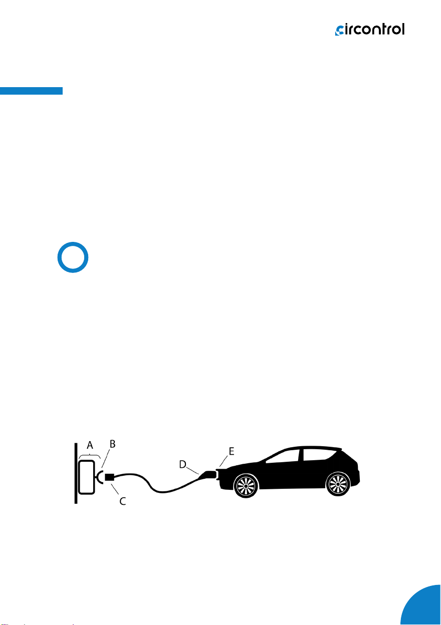
• A) Charging Station
• B) Socket-outlet
• C) Plug
• D) Vehicle connector
• E) Vehicle inlet
Abbreviations
B

Wallbox & Post eVolve Smart - User Manual
08
1 — Hat
2 — LED Beacons
3 — Display LCD
4 — RFID Reader
5 — Socket-outlet*
6 — Key lock access
7 — Base
8 — Wall support
(*) Socket-outlet may vary depending on the model
5
6
12
7
3
4
3
1
3
7
8
6
6
4
8
5
2

09
MAIN FEATURES OF THE UNIT
Charge Point may not include elements of electrical protection.
• Display: Information about
the status of the connectors
and detailed data as kWh
and duration time.
• Connector Lock: Type 2
connector has a lock system
to avoid disconnection of EV
meanwhile is charging.
• Light beacon: RGB led
indicates the status of the
connectors.
• RFID: User authentication.
• Ethernet:
• Wi-Fi connection: To avoid
using Ethernet cable.
• 4G Modem (optional): For
those places where wired
communications are not
sufcient.
• Energy metering: Integrated
meter built is measuring
power and energy consumed
by the EV during a charge
transaction.
• Remote access: For
supervision and control from
everywhere.
• Chargetransactionhistorics:
Charge Point is capable of
storing information about the
charge transactions.
• OCPP: Open standard
communication protocol,
allows communication
between the Charge Point
and the Central System.
communication for remote
supervision and conguration.
TCP/IP
Features

Wallbox & Post eVolve Smart - User Manual
10
4
Before Start Charging
Before doing anything, the Charge Point’s Display shows the following
sequence of messages:
A
Start Charging
B
1. The rst step is to show the RFID card to the reader*
Oncedone, the LedBeacon turnsBlue and theDisplayshows thefollowing
sequence of messages:
*IftheRFIDcardreaderisdisabled,chargetransactionstartsautomatically
when a vehicle is detected.

11
How to use it?
2. Plug the cable to the vehicle, choose one available socket (in case
there are more than one) and plug the cable to the Charge Point.
Once done, the Display shows the following message:
After the last message, the Display shows the following sequence of
messages while charging:
OR
OR
OR
Wallbox & Post eVolve Smart - User Manual
12
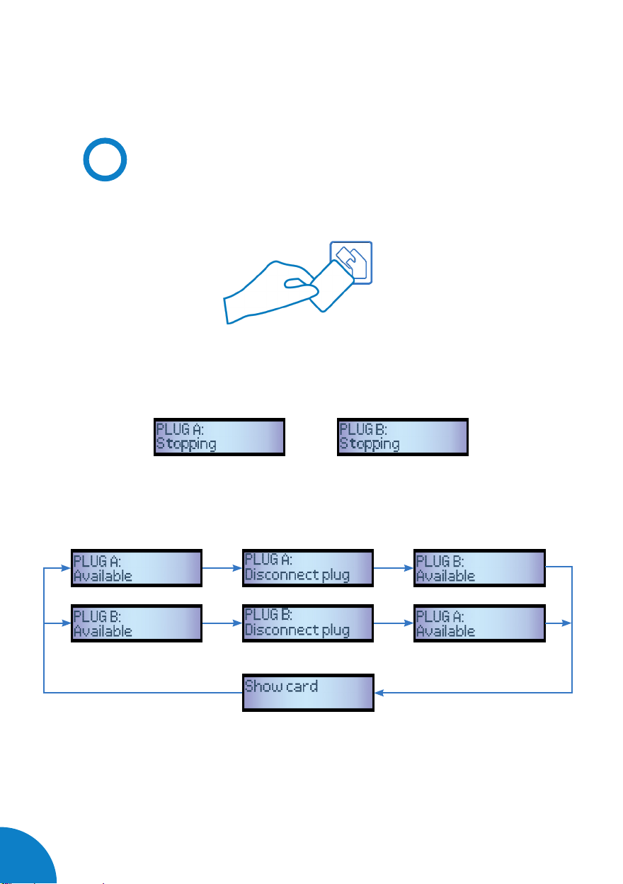
Stop Charging
1. The rst step is to show the RFID card to the reader*
Once done, the Led Beacon turns Green and the Display shows the next
message:
*If the RFID card reader is disabled, charge transaction stops automatically
when a cable is disconnected from the vehicle.
C
After the last message, the Display shows the next sequence:
OR
OR

13
2. Unplug the cable from both sides.
Once done, the connector becomes available and the Display shows the
following sequence of messages:
Wallbox & Post eVolve Smart - User Manual
14
5
The eVolve Smart is capable of detecting the following operating errors.
All of them will be displayed with a specic number of red light blinks:
- D state Error
- E state Error
- Proximity Error
- Negative PWM voltage Error
- Non-current selected Error (Dip-Switch)
- Welded contact Error
- Locking System Error
- Communication Error
- No input voltage Error
- Maximum temperature Error
- Minimum temperature Error
Whatever the error case is, the Charge Point will stop charging and
technical assistance will be required, except from the temperature errors.
In this last case, the Charge Point starts charging when the operating
temperature is reached again.
In the following sections it will be explained how the eVolve indicates the
above mentioned errors and the actions taken by the Charge Point.
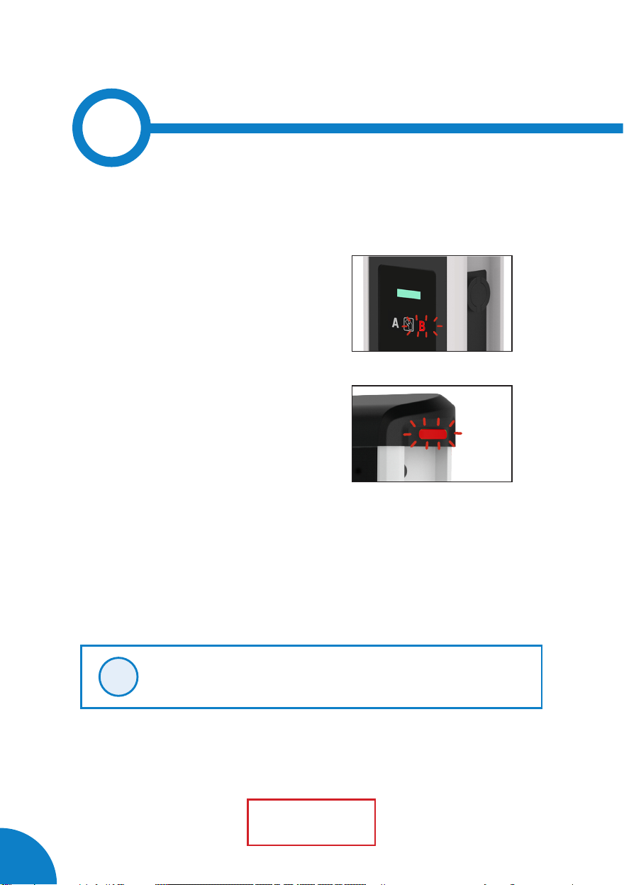
1 — D STATE ERROR
In some old EVs, this state means that there are some gases coming out
from the batteries. So, an external ventilation in the car park might be
required. If this is the case, the status LED bar ashes permanently.
1Blink Sequence
Please note each LED beacon is independent of the other.
i
Wallbox
Post

15
Status LED beacons’ errors
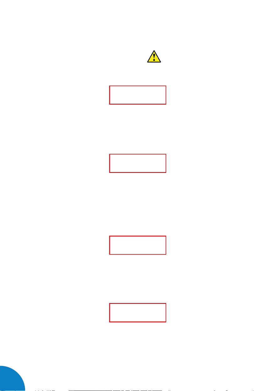
2 Blink Sequence
2 — E STATE ERROR
This means that there has occurred a communication error between the
EV and the Charge Point. If this is the case, the status LED light bar ashes
in a sequence of two blinks.
3 — PROXIMITY ERROR
When the Charge Point is connected to the EV, a Proximity short-circuit to
earth may occur. The, the status LED light bar turns ashes in a sequence
of three blinks.
4 — NEGATIVE PWM VOLTAGE ERROR
When the Charge Point is connected to the EV, the PWM signal, used to
communicate the Charge Point with the EV, can be negative. Then, the
status LED light bar ashes in a sequence of four blinks.
5 — NON-CURRENT SELECTION ERROR (DIP-SWITCH)
If the on-board current limit selection is not set up according to the
hardware features, the Charge Point detects it and shows this error. In this
case, the status LED light bar ashes in a sequence of six blinks.
3 Blink Sequence
4 Blink Sequence
6 Blink Sequence
Wallbox & Post eVolve Smart - User Manual
16
6 — WELDED CONTACT ERROR
An internal short-circuit has been detected. In this case, the status LED
light bar ashes in a sequence of seven blinks.
7 — LOCKING SYSYEM ERROR
This may occur if the connector is not properly connected to the socket-
outlet. In this case, the status LED light bar ashes in a sequence of eight
blinks.
8 — COMMUNICATION ERROR
This means that there has occurred a communication error. If this is the
case, the status LED light bar ashes in a sequence of nine blinks.
9 — NO INPUT VOLTAGE ERROR
This means that there is not input voltage going throw the Mode 3 PCB. If
this is the case, the status LED light bar ashes in a sequence of ten blinks.
7 Blink Sequence
8 Blink Sequence
9 Blink Sequence
10 Blink Sequence
Other manuals for eVolve Smart Series
1
Table of contents
Other Circontrol Automobile Batteries Charger manuals


