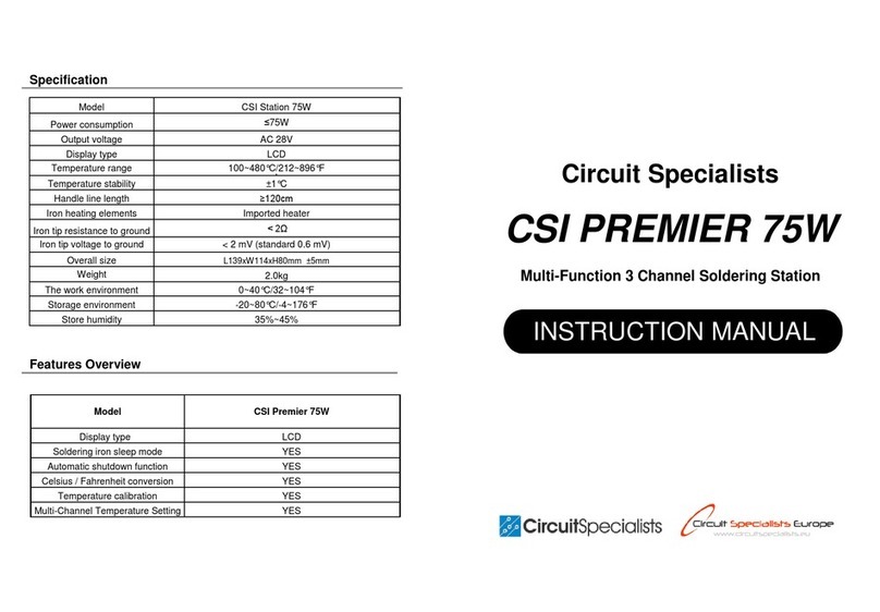
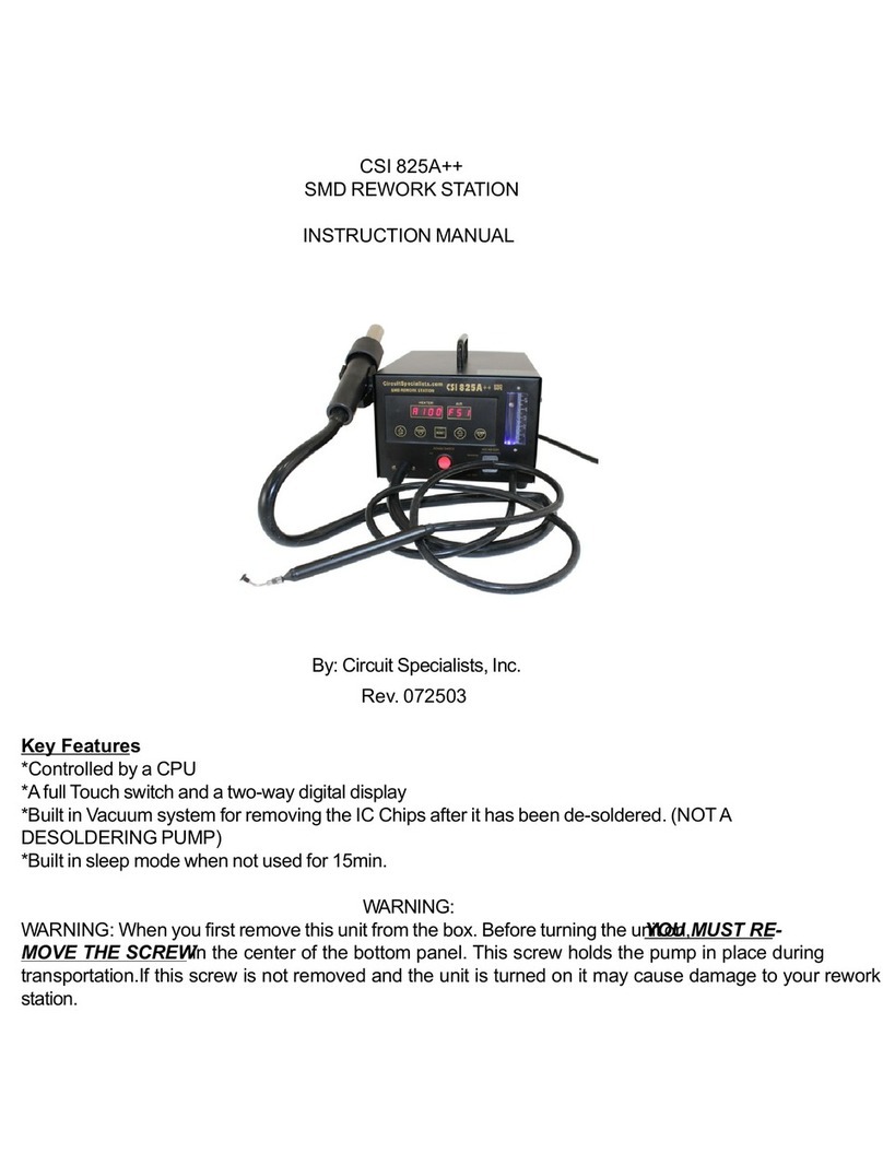
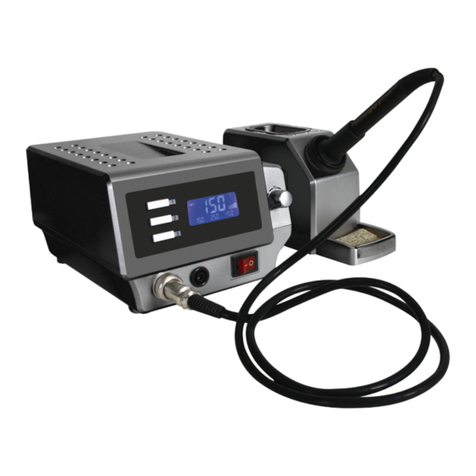
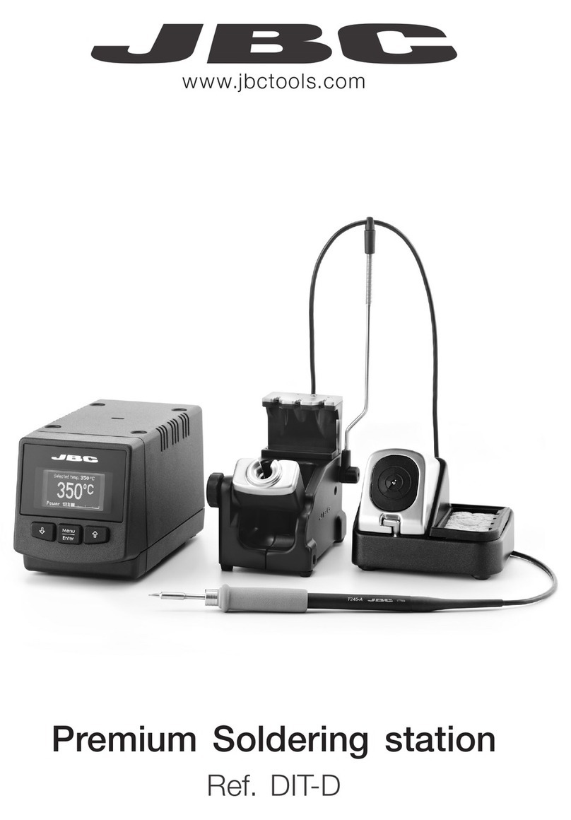
Circuit Specialists CSI-PREMIER-110W Technical manual

MadeinChina
Statement:Thecompanyreservestherighttoimprove&upgradeproducts,
product specifications and design are subject to change without notice.
Thank you for purchasing this product. Please read the manual
carefullybeforeoperatingandkeepthismanualforfuturereference.
English
Soldering Station
ESD Safe & Temperature-Adjustable
O P E R AT I O N
INSTRUCTION
939D+-3 110W 04.07.03.467

01 02
INSTRUCTIONS
II. PART LIST
1.SolderingIron
2.MagnifyingGlasswithLEDLights
3.Settemperature
4.Actualtemperature
5.MemoryChannelButtons(4-channels)
6.TemperatureAdjustmentDial
7.Powerswitch
8.Holder(SolderingIron)
9.SolderingTipCleaner
10.ResidualTray
11.HelpingHand(Multi-purposeclip)
12.Receptacle(SolderingIron)
III. INSTRUCTIONS
1. Depending on the users’ preferences, it is optional to install the soldering iron holder either
at the side of the station or on top of the station. Install the holder as per the diagrams below:
2. Connect the soldering iron to the station, and place the soldering iron into the iron holder.
3. Solder Roll Bracket Facing Up → Slot the solder roll bracket into the installation rails → Push
the solder roll bracket all the way to the bottom.
Installation Slot (Female)Installation Slot (Male) Screw Hole (Soldering Iron Holder)
Insert the Installation Slot (Male) into the Installation Slot (Female).
→ Install the screw into the soldering iron holder’s screw hole to secure the holder.
Solder Roll Slot
Installation Poles
(Bracket)
Mainunitdimensions
Tiptogroundresistance
Temperaturerange
Display
Operatingambienttemperature
L168xW128xH185mm±5mm
LCD
0〜40℃/32℉〜104℉
200℃~480℃/392℉~896℉
<2 ohms
Ⅰ. APPLICATION
4. Refer to the parts list; Install and tighten the screws of the two helping hands on the left and
right sides of the station.
5. Connect the station's power cord to an electrical outlet, and turn ON the power switch. The
station's heating element will begin heating, and the station's operating indicator(the dot on
the display’s bottom right) will turn ON. The light will be ON constantly when heating, blink-
ing when the temperature is stabilized, OFF when cooling. Once the station's indicator light
is blinking periodically and enters temperature stabilization, begin your operation.
CAUTION: The installation and removal of the iron holder and the solder roll bracket MUST be carried
out ONLY when the soldering iron is cooled.
1
2
3
4
5
6
7
8
9
10
11
12
This unit is suitable for de-soldering and soldering applications on various surface-mount com-
ponents and through-hole components, such as SOP, DIP, SOIC, etc.

03 04
6. When the operation is complete, use a damped sponge or metal wool ball to clean the solder-
ing iron tip. Tin the tip with a new layer of solder again, then put the soldering iron back to the
holder, and turn OFF the power switch. If the station is not in use for an extended period,
DISCONNECT the power cord.
Indicator for program tracking temp. at
high speed and making temp. compensation.
CAUTION: Upon the first use of the soldering iron, set the temperature to 250°C/482°F. When the iron is
just hot enough to melt solder, coat the soldering iron tip with a layer of solder (the use of rosin core sol-
der is recommended), then set the temperature to your desired temperature.
User Preset Channels (4 available channels)
Press the CH1 button, and the display will show the ① icon, turn the temperature adjustment
dial to set your desired temperature, the system will save the data automatically. Press CH2,
CH3, and CH4 respectively to set the respective temperatures.
SET
3
Sleep Mode Timer Duration (Soldering Station)
1. Turn on the soldering station’s power switch.
2.Press and hold the temperature adjustment knob for
approximately 2 seconds. The display will show the value
"SLP 5", indicating the Sleep Mode timer is set to 5 minutes.
3.Turn the temperature adjustment knob to change the
sleep duration. Wait for approximately 5 seconds to exit
the setting interface- setting complete.
The sleep mode timer can be set to 5/10/15/20/30 minutes.
Select “OFF” to turn OFF sleep mode.
To wake the station:
a. shake the soldering iron a couple of times;
b. press any button;
Or c. Turn OFF then turn ON the power switch.
Buzzer Prompts
1. Turn on the soldering station’s power switch.
2. Press and hold the temperature adjustment knob for
approximately 2 seconds. The display will show the value
"SLP XX”. Press the button once more, the display will
show "bL OFF", indicating the buzzer prompt is turned off.
3. Turn the temperature adjustment knob to turn ON or OFF
the buzzer prompt. Wait for approximately 5 seconds to
exit the setting interface- setting complete.
C
Digital Temperature Calibration
1. Turn on the switch to the soldering station.
2. Press and hold the temperature adjustment knob for approxi-
mately 2 seconds. The display will show the value "SLP XX”.
Press the button twice more, the display will show "CAL 300"
to enter the temperature calibration interface.
3. Turn the adjustment knob to enter the measured temperature
and press the knob to confirm the entry. The system will auto-
matically save the data and exit the temperature calibration.
If there is still temperature discrepancy, repeat the above calibration procedures.
Temperature discrepancies may occur due to the change in the environment's temperature or due to the
replacement of the heating element and other components. You can correct the discrepancies with this
function. The temperature calibration can help improve work efficiency and prolong the lifespan of the
soldering iron.
°F /°C Temperature Unit Conversion
This function allows the station to comply with user preferences in different regions.
Press the temperature adjustment knob to select Fahrenheit or Celsius display.

05 06
V. TROUBLESHOOTING
1. "S-E" – This is an indication that the station's sensor module is faulty. You need to replace
the heating element (the heating element and the sensor modules). Or it may be that the
soldering iron has not been connected (Turn OFF the power, connect the soldering iron, th-
en turn ON the station again.).
2. "O-E" – This is an indication that the system detects abnormalities during the heating proc-
ess. In such an instance, you need to replace the heating element (the heating element and
the sensor modules) or inspect the heating element's power circuitry.
3.When replacing the heating element, take notice of the original connecting order and colors
of the wires which MUST NOT be connected incorrectly.
IV. MAINTENANCE & PRECAUTIONS
1. If a layer of oxidization forms on the surface of the soldering iron tip, a misconception can be
created that the soldering tip cannot heat up properly to melt the solder and do the tinning.
But the actual temperatures of both the heating element and soldering tip are high. In such
an instance, please do not increase the temperature value confusedly but use a metal wool
ball to remove the oxidization following the steps below:
2. DO NOT use metal files to remove the oxidization on the soldering iron tip. If the soldering ir-
on tip deforms or rusts, replace the soldering iron tip with a new tip.
3. DO NOT apply excessive forces on the soldering tip when soldering. Doing so will not only da-
mage the iron tip but also not improve the heat transfer.
4. When returning the soldering iron to the holder after a high-temperature operation, always
turn the temperature down to below 250℃(482℉)to idle. Allowing the soldering iron to
idle in high-temperature will shorten the lifespan of the soldering iron and heating element.
Additionally, this will also result in the premature aging of the heating element.
5. After every operation, always clean and tin the iron tip with a layer of solder to prevent oxidi-
zation.
A. Set the temperature to 300°C(572°F)
B. After the temperature has stabilized, gently rub the soldering iron tip inside the metal wool.
C. When the oxidization is partially removed, continue applying the solder on the soldering tip while
rubbing until the iron tip is completely coated with a layer of solder. If the oxidization is too severe
beyond cleaning, replace your soldering iron tip.
Tipstyle(specificationsandsizes)
902SeriesTipOutDiamφ6.5mm
902-B
902-I
902-K
902-3.2D
902-3C
Other Circuit Specialists Soldering Gun manuals
