Circuit Specialists TC-V2.12k User manual

多功能测试仪(TC-V2.12k)
Multi-function Tester (TC-V2.12k)
2017-4-62015-8-8 版权所有,侵权必究 All rights reserved 第14 页,共25 页Page 14 , Total25
Multi-function Tester (TC-V2.12k)
1Overview
1.1 Introduction
① - 160x128 TFT display
② - Multi function key
③ - Transistor test area
④ - Zener Diode test area
⑤ - IR receiver window
⑥ - Micro USB Charging Interface
⑦ - Charge indicator LED
多功能测试仪(TC-V2.12k)
Multi-function Tester (TC-V2.12k)
2017-4-62015-8-8 版权所有,侵权必究 All rights reserved 第15 页,共25 页Page 15 , Total25
1.2 Features
TC-V2.12k is a TFT graphic display Multifunction Tester.
Transistor Tester
-Automatic detection of NPN and PNP bipolar transistors, N-channel and P-channel
MOSFETs, JFETs, diodes (including double diodes), N- and P-IGBTs, resistors
(including potentiometers), inductors, capacitors, thyristors, triacs and battery
(0.1-4.5V)
-Automatic detection of zener diode(0.01-30V)
-Self test with automatic calibration
IR decoder
-Support Hitachi IR coding
-IR waveform display
-Infrared receiving instruction
Other
-Measurement results using TFT graphic display(160x128)
-One key operation
-Auto Power Off(Timeout Settable)
-Built-in high capacity rechargeable Li-ion Battery
-Li-ion Battery voltage detection
-Support Chinese and English
Warning: Built-in Li-ion Battery, it is strictly prohibited the tester immersed in water,
or near a heat source!
Warning: For your personal safety, please strictly comply with the use of Li-ion
Battery specifications and precautions!
多功能测试仪(TC-V2.12k)
Multi-function Tester (TC-V2.12k)
2017-4-62015-8-8 版权所有,侵权必究 All rights reserved 第16 页,共25 页Page 16 , Total25
2Operating Instructions
2.1 Key operational definitions
Multi-function key has two actions:
Short press: Press the key and not less than 10 ms, release key within 1.5 seconds
Long press: Press the key more than 1.5 seconds
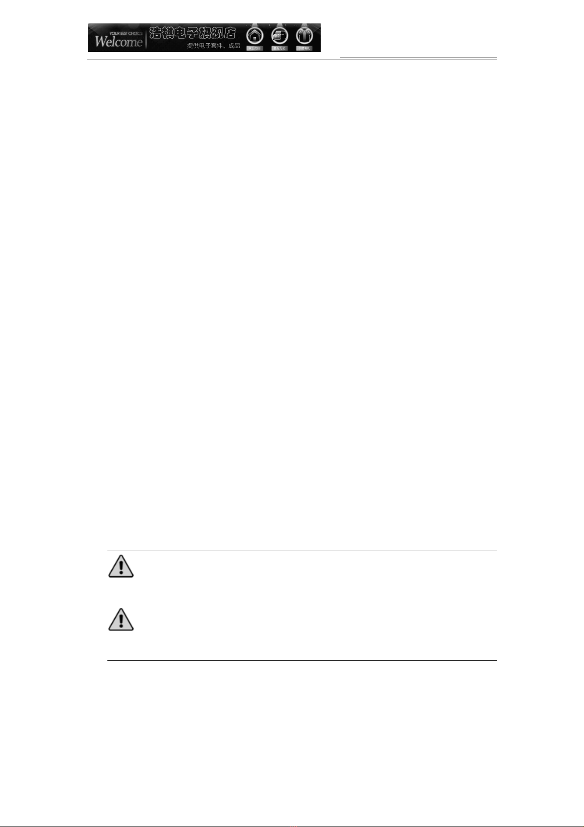
2.2 Power on
In the power off state, short press the multifunction key, the tester is turned on and
automatically measured.
Power on & measurement interface
2.3 Detect transistor
In the power off state or the test is completed, put the test element into the transistor test area
of test seat, and press the locking handle, short press the multifunction key, the tester
automatically measure, graphical display of measurement results when testing is complete.
Warning: Always be sure to DISCHARGE capacitors before connecting them to the
tester! The tester may be damaged before you have switched it on!
Warning: We do not recommend using the tester to measure the battery! The battery
voltage must be less than 4.5V, otherwise the tester may be damaged!
Component placement
Test seat are divided into transistors and zener diode test area, detailed in 1.1
Description.
No, unknown, or damaged part

多功能测试仪(TC-V2.12k)
Multi-function Tester (TC-V2.12k)
2017-4-62015-8-8 版权所有,侵权必究 All rights reserved 第17 页,共25 页Page 17 , Total25
Battery
BJT(Bipolar Junction Transistor)
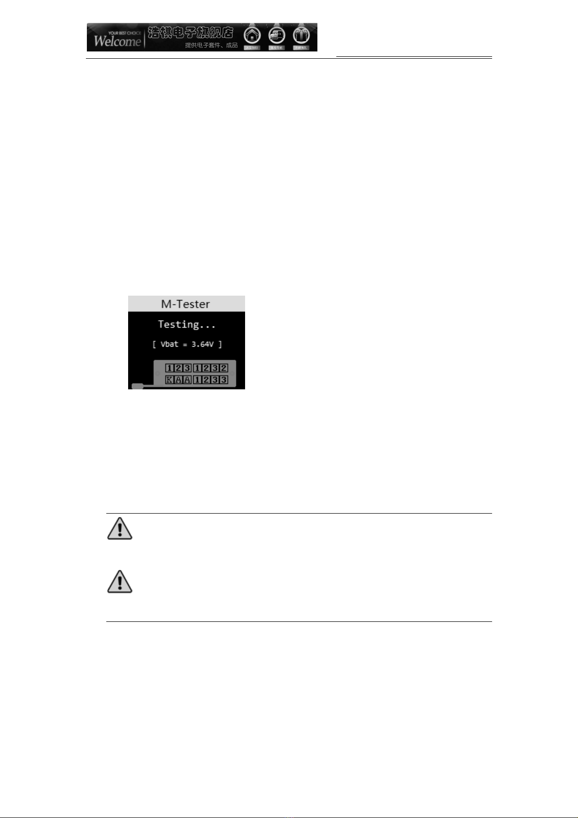
Diode
多功能测试仪(TC-V2.12k)
Multi-function Tester (TC-V2.12k)
2017-4-62015-8-8 版权所有,侵权必究 All rights reserved 第18 页,共25 页Page 18 , Total25
2 Diodes
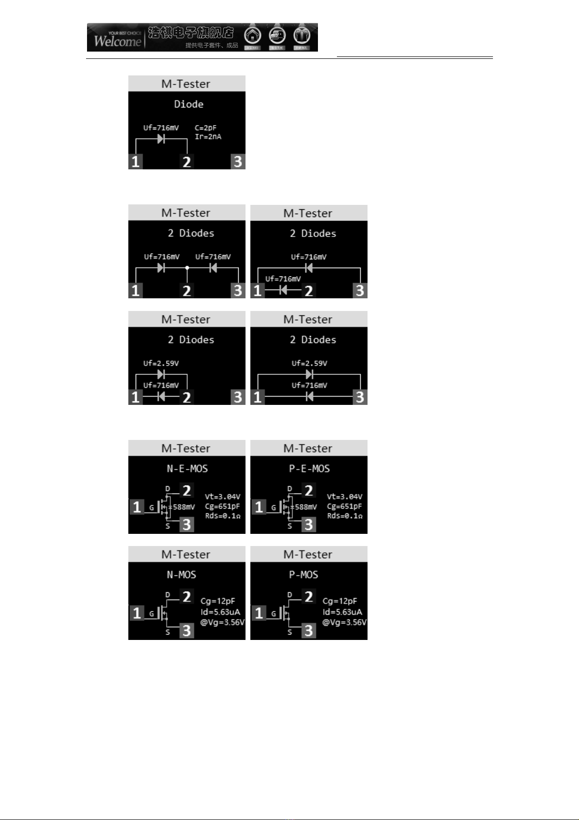
MOSFET
This manual suits for next models
1
Table of contents
Popular Test Equipment manuals by other brands


Redtech
Redtech TRAILERteck T05 user manual

Venmar
Venmar AVS Constructo 1.0 HRV user guide

Test Instrument Solutions
Test Instrument Solutions SafetyPAT operating manual

Hanna Instruments
Hanna Instruments HI 38078 instruction manual

Kistler
Kistler 5495C Series instruction manual

Waygate Technologies
Waygate Technologies DM5E Basic quick start guide

StoneL
StoneL DeviceNet CK464002A manual

Seica
Seica RAPID 220 Site preparation guide

Kingfisher
Kingfisher KI7400 Series Training manual

Kurth Electronic
Kurth Electronic CCTS-03 operating manual

SMART
SMART KANAAD SBT XTREME 3G Series user manual

Agilent Technologies
Agilent Technologies BERT Serial Getting started