Circuit-test PSC-4120 User manual

1
OPERATION
MANUAL
CIRCUIT-TEST
Switching Mode
Power Supply with
USB Remote Control
PSC-4120
1-20VDC / 5A
PSC-4136
1-36VDC / 3A
PSC-4160
1-60VDC / 1.6A

2
PSC-4120_4136_4160 08R18

3
Safety Precautions................................................................................page 4, 5
Introduction..................................................................................................... 6
Controls and Indicators.................................................................................... 7
Operations....................................................................................................... 8
PC Connection............................................................................................... 12
Specifications................................................................................................. 13
Command Set................................................................................................ 14
Warranty ....................................................................................................... 16
Contents

4
Keep this manual in a safe place for quick reference at all times.
This manual contains important safety and operation instructions for correct use
of the power supply. Read through the manual and pay special attention to the
markings and labels of this unit and equipment to be connected.
Pay special attention to these two types of notices used in this manual
WARNING:
Failure to observe this warning may cause injury to
persons and damage to power supply or connected equipment.
CAUTION:
Failure to observe this warning may result in damage
to equipment and improper functioning of the power supply.

5
Caution
1. Use a grounded 3 pin AC source.
2. This unit is for indoor use only.
3. Do not operate or place this unit in a humid, dusty, direct sunlight location or
near any heat source.
4. Before plugging into local AC mains, check the rating label at the back of
the unit.
5. Do not block any ventilation openings of the unit.
6. This unit must be used within the specified rating; regular excessive continuous
loading may cause damage to the power supply.
7. The gauge size of input power cable must be at least 0.75mm2and the total
length of power cable must not exceed 3m.
Warning
1. Do not use this power supply near water.
2. Do not operate or touch this power supply with wet hands.
3. Do not open the casing of the power supply when it is connected to
AC mains.
4. Refer all servicing to qualified service personnel only.
5. Before replacing the external AC fuse, determine and eliminate the
cause first.
6. Replace the AC fuse with the same type and rating as the original fuse.
7. The maximum output voltage of Model no. PSC-4160 is 60VDC; avoid
touching the metal portion of the output terminals.
Operation Environmental Condition
• 10-80% R.H. Maximum relative humidity 80% for temperature up to 31°C
decreasing linearly to 50% relative humidity at 40°C. Altitude up to 2000m
• Installation Category: CAT 2 Pollution degree: 2
• Mains supply voltage fluctuation up to ±10% of the normal voltage.

6
This family of Switching Mode Power Supplies offer current limiting control with
high accuracy and a space saving compact design with easy portability. It features
rotary encoder tuning with MCU for voltage and current control. The 4 digit LCD
display’s the voltage and current readings with high precision.
This power supply is ideal for trouble shooting circuit boards or devices that require
two or three different input voltages such as 3V or 5V, 12V and 1-36V.
This power supply can provide 3 outputs at the same time. All three outputs are
fully isolated so different cross connections of 2 or 3 outputs can provide various
fixed or variable output voltages. Any output can be connected for positive or
negative polarity. See as illustrated in connection diagrams.
Introduction
7
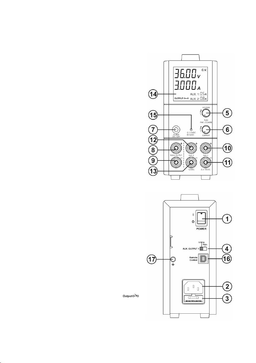
1. Power Switch:
- Turns the power supply ON/OFF, when it is ON the front display lights up
2. AC Input power socket
3. Fuse holder (ply open the cover to get to
the fuse)
4. 3.3V/5VDC selection switch (for Aux
output 1)
5. Output Voltage tuning knob. (Push the
knob to toggle the coarse and
fine tuning)
6. Output Current tuning knob. (Push the
knob to toggle the coarse and
fine tuning)
7. Output On/Off push button
- For Main output: Push this button to
turn the Main output ON/OFF
- For Main output & Aux outputs: Push
and hold this button for 3 seconds to
turn the Main and Aux outputs OFF,
push this button again to turn them ON
8. Main Output terminal Positive (+) Red
9. Main Output terminal Negative (-) Black
10. Aux Output 1 terminal Positive (+) Red
(3.3VDC or 5VDC selectable)
11. Aux Output 1 terminal Negative (-) Black
(3.3VDC or 5VDC selectable)
12. Aux Output 2 terminal Positive (+) Red
(Fixed 12VDC)
13. Aux Output 2 terminal Negative (-) Black
(Fixed 12VDC)
14. LCD Display panel indicating:
- 4 digit Voltmeter, Ammeter, (CV)
constant voltage mode, (CC) constant
current mode,
- Output terminal ON/OFF state
- 2 digit Aux outputs Ammeter
15. Aux 1 Output voltage indicator
16. USB remote control
17. Ground Terminal
Controls and Indicators

8
Operations
Basic Mode of Operation
This power supply is designed to operate as a constant voltage source or as a
constant current source. Automatic crossover to either mode of operation occurs
when the load condition changes as following:
Constant Voltage (CV), Automatic crossover &
Constant Current (CC)
The power supply functions as a constant voltage source (CV) as long as the load
current is less than the preset current limiting value. When the load current is
equal to or greater than the preset current limiting value, the power supply will
automatically cross over to the constant current mode, voltage will drop, (CC) will
show on the LCD display panel and it will operate as a constant current source.
When the load current drops below the preset current limiting value, the supply
returns to constant voltage (CV) mode.
Set the Output Voltage and Presetting Current Limiting Value (CC)
Turn the voltage or current knob to set the desired values.
Quick pushes on the knobs will move the decimal place for fast tuning.
Turn the knob when the desired number column flashes otherwise will need to
repeat quick pushes again.
One quick push on the current knob will display the preset current limiting value.
Aux. output 1 voltage selection
Move the switch 4 at the back of power supply for selection of 3.3 or 5 VDC.
At 3.3VDC setting, indicator 15 will be Off and at 5VDC setting indicator 15 will
be ON.
Connecting and Operating Procedure
1. Check the rating label and plug in to AC mains.
2. Switch on the power supply and the LCD display should be ON at the
same time.
3. The (CV) icon will appear on the display.
4. Turn Current knob 6 to maximum clockwise if you do not require lower
current limiting value, otherwise do the preset the (CC) limiting procedure.
5. Set your desired output voltage and then turn off the output terminal with
push button 7 .
9
6. Connect to your load positive to positive and negative to negative.
7. Turn on the output terminal again and check if display shows (CV).
8. If display shows (CC), either your pre-set current limiting value is too low or
your load requires more voltage and current. You need to re-access the volt-
age and current requirement of your load and increase the voltage or current
accordingly until (CV) appears.
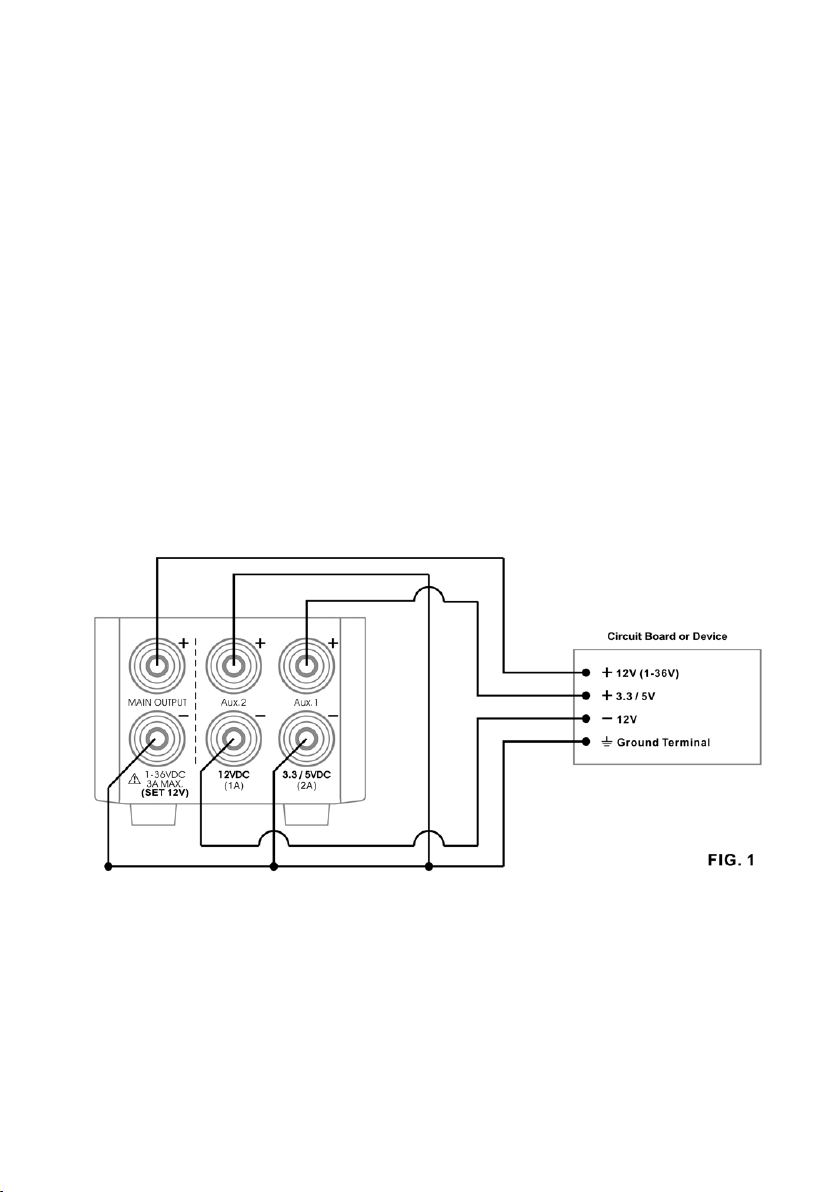
Connecting the 3 outputs (using PSC-4136, 1-36V, 0.25-3A as an example)
All the three outputs are fully isolated from ground and with each other so that
it is possible to make cross connections to power a circuit board or device that
requires for example: +3 or +5V, +12 V or -12V and 1-36V as shown in Fig.1.
The variable main output is set for 12V and it is assigned as the +12V source
(available maximum current 3A) Note: the variable main output can be set for
other voltage (1-36V) such as 16V.
The fixed 12V is made as the - 12V source (available maximum current 0.5A)
The fixed 5V is made as the +5V source. (available maximum current 0.5A)
Figure 1 Diagram showing Circuit Board or Device

10
Connecting outputs in series (using PSC-4136 as an example)
You can have a 17V fixed output by connecting the 5V in series with the 12V
outputs.
The 2 outputs (Aux.1) can be connected in series to make a variable 5V to 41V
with maximum current 2A (Fig. 2)
The 3 outputs can be connected in series to make a variable 17V to 53V with
maximum current 1A, (Fig. 3)
There are other combinations of cross connections for different positive and nega-
tive output voltages.

11
Tracking Output Over Voltage Protection (OVP)
This is to protect the connected load in the event that the output voltage control
circuit malfunctions, the maximum output voltage will not exceed 30% of the
adjusted voltage value at the time of the operation.
Over Temperature Protection
When the temperature inside the power supply becomes higher than a pre-deter-
mined value, the output voltage and current of the power supply will automati-
cally decrease to zero to prevent damage to power supply. When the temperature
inside the power supply returns to normal the power supply will automatically
return to operation again.

12
This power supply with USB feature can be remotely controlled using Windows PC.
Connect the power supply to PC using supplied USB cable.
There are two ways to remotely control this power supply; with the PC control
software downloadable from the website www.circuittest.com or with your own
program using the command sets provided in this manual.
For detailed usage of driver and the PC software please refer to PC software manual
downloadable from the website www.circuittest.com. Please make sure to down-
load the appropriate driver and software for the respective power supply model.
PC CONNECTION

13
PSC-4120 PSC-4136 PSC-4160
Input Voltage 105 - 135VAC / 60Hz
Full Load Input Current at 120Vac 1.3A
Output Voltage Adjustable Range 1.0 - 20Vdc 1.0 – 36Vdc 1.0 - 60Vdc
Output Current Adjustable Range 0.25 - 5A 0.25 - 3A 0.25 - 1.6A
Voltage Regulation
Load from 10% to 90% Variation
Line from 105 to 135Vac Variation
Ripple & Noise (peak to peak)
≤70mV
≤25mV
≤120mV ≤150mV ≤180mV
Current Regulation
Load from 10% to 90% Variation
Line from 105 to 135Vac Variation
Ripple & Noise (peak to peak)
≤50mA
≤20mA
≤50mA
Switching Operation Frequency 50KHz to 150KHz
Aux output 1 Fixed 3.3 /5VDC. 1.8A continuous. 2A Max.
Aux output 2 Fixed 12VDC, 800mA cont. 1A Max.
Power Factor >0.9
Efficiency at Maximum Power ≥80.5% ≥80.5% ≥80.5%
Volt and Amp Control Type Rotary Encoder
Voltmeter and Ammeter Display 4 Digit LCD
Voltmeter Accuracy 5 counts for range V<5V
±0.2% +5 counts for range V≥5V
Ammeter Accuracy 15 counts for range I≤1A
±0.5% +6 counts for range I>1A
LCD Indication CC, CV, Amp, Volt, Output ON-OFF, Aux output current
Protection Short Circuit, Overload, Over Temperature, Tracking OVP
Cooling System Natural Convection
Dimensions (WxHxD) 70 x 150 x 250mm / 2.8 x 6.0 x 9.8in.
Weight 2Kgs / 4.4Lbs
SPECIFICATIONS

14
Command code & Return Value Description Example
Input Command:
SOUT<Output>[CR]
Return Value: [OK][CR]
Set Output on/off
Set Output off: <Output>=0
Set Output on: <Output>=1
Input Command: SOUT0[CR]
Return Value: [OK][CR]
Meaning: Set Output off
Input Command: GOUT [CR]
Return Value: <Output> [CR][OK]
[CR]
Get Output Status
Output off: <Output>=0
Output on: <Output> =1
Input Command: GOUT[CR]
Return Value: 0[CR][OK][CR]
Meaning: Output is off
Input Command: SETD
<VOLTAGE><CURRENT>[CR]
Return Value: [OK][CR]
SET Voltage and Current
<voltage> =0000~3640
<Current> =0000~5100
Input Command:
SETD05001000[CR]
Return Value: [OK][CR]
Meaning: Voltage 5.00V
Current 1.000A
Input Command: GETD [CR]
Return Value:
<Voltage><;><Current><;>
<CV/CC Mode><;>[CR][OK][CR]
Get display Volt & display
Curr & CV/CC mode
<voltage> =0~9999
<Current> =0~9999
<CV mode> =0 CV Mode
<CC mode> =0 CC Mode
Input Command: GETD [CR]
Return Value:
500;1000;0;[CR][OK][CR]
Meaning: The Display value
is 5.00V and 1.000A
It is CV mode
Input Command: GETS [CR]
Return Value:
<Voltage><;><Current><;>[CR]
[OK][CR]
Get Setting Volt & Curr
<voltage> =0~3640
<current> =0~5100
Input Command: GETS[CR]
Return Value: 500;1000;[CR]
[OK][CR]
Meaning: The Memory set-
ting voltage value is 5.00V
and Current is 1.000A
Input Command:
VOLT<Voltage>[CR]
Return Value: [OK][CR]
Set output voltage Input Command: VOLT
1000[CR]
Return Value: [OK][CR]
Meaning: Set voltage value
is 10.00V
Input Command:
CURR<Current>[CR]
Return Value: [OK][CR]
Set output current Input Command:
CURR1000[CR]
Return Value: [OK][CR]
Meaning: Set Current value
is 1.000A
COMMAND SET

15
Command code & Return Value Description Example
Input Command: GMOD [CR]
Return Value: <MODE>[CR][OK]
[CR]
Get MODE
<MODE>=NTP????
Input Command: GMOD[CR]
Return Value: NTP5521[CR]
[OK][CR]
Meaning: Mode is NTP5521
Input Command: GVSH [CR]
Return Value: <Voltage>[CR][OK]
[CR]
Get voltage set high limit
<voltage>=????
Input Command: GVSH [CR]
Return Value: 3600 [CR]
[OK][CR]
Meaning: voltage set high
limit is 36.00V
Input Command: GVSL [CR]
Return Value: <Voltage>[CR][OK]
[CR]
Get voltage set low limit
<voltage>=???
Input Command: GVSL [CR]
Return Value: 100 [CR][OK]
[CR]
Meaning: Voltage set low
limit is 1.00V
Input Command: GISH [CR]
Return Value: <Current>[CR][OK]
[CR]
Get current set high limit
<Current>=????
Input Command: GISH [CR]
Return Value: 5500 [CR]
[OK][CR]
Meaning: Current set high
limit is 5.500A
Input Command: GISL [CR]
Return Value: <Current>[CR][OK]
[CR]
Get current set low limit
<Current>=???
Input Command: GISL [CR]
Return Value: 250 [CR][OK]
[CR]
Meaning: Current set low
limit is 0.250A
Input Command: GMAX [CR]
Return Value:
<Voltage><;><Current><;>[CR]
[OK][CR]
Get voltage set high limit &
current set high limit
<voltage> =????
<current> =????
Input Command: GMAX [CR]
Return Value: 3600;5500;[CR]
[OK][CR]
Meaning: Voltage set high
limit is 36.00V & Current set
high limit is 5.500A
Input Command: GMIN [CR]
Return Value:
<Voltage><;><Current><;>[CR]
[OK][CR]
Get voltage set low limit &
current set low limit
<voltage> =???
<current> =???
Input Command: GMIN [CR]
Return Value: 100;250;[CR]
[OK][CR]
Meaning: Voltage set low
limit is 1.00V & Current set
low limit is 0.250A

16
Circuit-Test Electronics warrants to the original purchaser that this product be
free of defect in material or workmanship for a period of 2 years from the date
of purchase.
Any product which has been subjected to misuse or accidental damage is ex-
cluded from the warranty. Except as stated above, Circuit-Test Electronics makes
no promises or warranties either expressed or implied including warranties of
merchantability or the fitness for any particular purpose.
Warranty

17
Notes:

18
CIRCUIT-TEST
ELECTRONICS
Division of R.P. Electronic Components Ltd.
BURNABY, BC CANADA V5J 5M8
This manual suits for next models
2
Table of contents
Other Circuit-test Power Supply manuals

 User manual")


