CircuitWerkes AC-3 User manual
1
AC-3
Auto Coupler
CircuitWerkes
Technical Manual
CircuitWerkes
3716 SW 3
rd
Place · Gainesville, FL 32607
(352) 335-6555 · Fax (352) 331-6999
c 1992-1996 CircuitWerkesAllRightsReserved.Allinformationcontainedwithinisproprietary.
NopartofthismanualmaybereproducedorcopiedwithouttheexpresswrittenconsentofCircuitWerkes.

2
Contents
INTRODUCTION ................................................................................................................ 3
SPECIFICATIONS ............................................................................................................... 3
CONNECTIONS................................................................................................................... 4
DESCRIPTION OF CONNECTIONS: ...................................................................................... 4
BOARD LAYOUT................................................................................................................ 4
OPERATION ................................................................................................................. 6
TROUBLESHOOTING ........................................................................................................... 6
AC-3 SCHEMATIC DIAGRAM ............................................................................................... 7
RINGS, BEEPS, AND SUCH .................................................................................................. 8
APPENDIX A.................................................................................................................... 9
OPTIONS FOR THE AC-3.................................................................................................. 9
REPAIR OR SERVICE INFORMATION ..................................................................................... 10
CIRCUITWERKES LIMITED WARRANTY ............................................................................. 10

3
INTRODUCTION
Thank you for buying the CircuitWerkes AC-3 autocoupler.
The AC-3 is a hybrid autocoupler with provisions for remotely controlling and monitoring its functions.
The integral analog hybrid provides for some separation of incoming and outgoing audio. Built-in
active audio limiting on the send line keeps outbound levels from exceeding -9 dBm into the phone line
while keeping average levels high. Normally open relay contacts (K2 on the terminal strip) close when
the unit picks up for tripping external play devices or as an on-line indicator.
SPECIFICATIONS
Power : Supplied wall transformer or other 12 volt or higher (AC or DC) supply.
Polarity is unimportant. Online current draw <100mA. Offline current draw is approx 20mA.
Audio In: Unbalanced 50k input impedence.
Audio Out: Low impedence (approx 250 Ohm) unbalanced output with approximately 10dB of gain
over normal phone line levels (which brings the output level up to about 0dBm on peaks).
Relay contacts: The N.O. contacts from SIP relay K2 close upon pickup (jumper J3 selects whether the
closure is momentary or latching for the duration of the call) and are good for 10VA up to 30 volts.
Higher voltages or currents should be slaved to a suitably large relay. If you slave a big relay off K2's
contacts be sure to use a snuffer diode so the inductive kick from the coil of the slave relay won't weld
K2's contacts.
QUICK SETUP:
Connect power and audio connections to the appropriate terminals. ( a diagram and descriptions can be
found on the next several pages of this manual). Set J1 for how many rings on which the unit will
answer. If you change jumpers on the AC-3, you have to re-power the coupler before the changes
willtake effect. Call the AC-3. While on-line with it, push S1 and adjust vr-2, the audio in level pot for
a comfortable listening level. With a small screw driver and an audio meter or amplified speaker con-
nected from aud. out and ground, adjust vr1, the "null" pot for minimum audio on the speaker or meter.
Note: vr1 is factory adjusted and will probably work just fine without adjusting, if desired, especially if
audio will only be sent in one direction at a time. Your unit is now ready to couple audio to/from the
phone line. Detailed setup and connection instructions can be found on pages 4 through 6 of this
manual.

4
CONNECTIONS
Installation is fairly straight forward. Captive-wire screw terminals make all connections to the unit
except for the Telco line which attaches to the RJ-11 jack. Mount your AC-3 away from excessive
high temperatures and humidity, wire it up and operate it as follows:
DESCRIPTION OF CONNECTIONS:
1) Power. The stripped and tinned leads of the supplied wall transformer go here. Polarity of the
supply leads is not important.
2) N/A. Used on ComboLok models ONLY.
3) N.O. contacts for AUX Relay (K2). Jumper J3 determines whether this relay closure is momentary
(about 200 milliseconds) or latching for the duration of the call.
4) Audio Out. Approximately 250 Ohm line level output. Unbalanced. 0dBm peak level.
1) Power
Supply: 12) Call End
O/C Out
9) Pickup
enable
2) K3 is only on
CombLok models
3) N.O. contacts
from AUX
relay K2.
5) Audio In
4) Audio out
6) Audio Input
Level Control Pot
7) Hybrid
Null Pot
8) RJ-11 Telco
Connection
10) Manual
Pickup 11) Ring & Line
Current O/C Output
BOARD LAYOUT
13)
Ring Set
Jumper J1.
J2
15)
Beep Enable
Jumper J3.
14) K2
mom. or
latch
jumper J2
incorrectly
marked J3
on board.

5
5) Audio In. Approximately 50k input impedence. Can be driven with straight -10 to +10 unbal-
anced audio. Integral active limiter keeps average levels high while limiting maximum to legal FCC
level of -9dBm. Adjust input level control for desired compression/level.
6) Input Level Control. Single turn pot. Adjust for best audio level or clarity.
7) Hybrid Null. Should be adjusted upon initial installation. Built in tone generator makes setting the
null easy. See "Hybrid Null," on page 6.
8) RJ-11. Telco connection here. Center two conductors are tip and ring. Any standard/generic line
cord (like the one we provide) will work fine. Normal dial-up "Loop Start" lines only. Ground start
PBX telephone lines are not directly compatible with autocouplers. If you are hooking the AC-3 up
to a PBX analog extension (an analog extension from a telephone system that emulates a normal dial-
up phone line) you may want to read about the CircuitWerkes CP-1 in the Options section at the end
of this manual. If you are in an area prone to lightning you should consider telephone line surge
suppression. CircuitWerkes warranty does not cover lightning damaged equipment.
9) Ring Thru / Pickup enable. This pair of contacts must be shorted (normally jumpered by J4 just
behind the terminal strip) for the unit to detect incoming rings. The contacts must also be shorted for
the AC-3 to detect line current. If line current detection is interrupted during a call, the coupler will
hang up.
A remote mounted switch attached to these two conductors could be used to control whether the
coupler answers and to force a hangup of an already-answered call. The pin labelled 'p' is the micro-
processor pull-up while the pin labelled 'c' is the collector of the ring/line optocoupler.
10) Manual pick up. Connected in parallel to S1 (behind the terminal strip), these two conductors
can be shorted while the unit is OFF Line to initiate an instant pick up. On stock AC-3 units (No
ComboLok installed) this switch also initiates a ten-second tone output for nulling purposes if the unit
is ONLINE when the switch is pressed.
11) Opto O/C. Ring detect and line current detect optocoupler U1 drives this open collector output.
When a ring occurs, or when line current is flowing, this open collector transistor output will be
active.
12) Call end. A momentary open collector output that occurs at the end of each call.
13) Ring select J1. Jumper positions for setting how many rings the AC-3 should answer on. Unit
comes factory strapped to answer after the second ring.
14) AUX L/M J2. Jumper position for selecting momentary or latching action on AUX relay, K2. If
jumper shorted, K2 is momentary and closes for about 200 milliseconds just after a call is picked up.
If J2 is open, K2's contacts close upon pickup and remain closed until the unit hangs up.
15) Beep Enable J3. This jumper can be removed if you wish to have no beeps. If the jumper is left
on, beeps will occur at pickup.

6
INSTALLATION / HYBRID NULL:
Once you've mounted your AC-3 and wired the power and Telco connections it is ready for the next to last
step,thehybridnulladjustment. This is accomplishedbymonitoringtheAC-3's audio output connectionwith
a console input, an amplified speaker, an o'scope or even an analog AC voltmeter. Dial up the coupler then
trigger the built-in tone generator (press S1 for stock AC-3). Adjust the Null Pot (VR1, besdie the RJ-11
connector)potforavisibleoraudiblenull. Thenull adjustment may have to be repeated if youchangephone
lines attached to the AC-3 or if your phone lines are modified, changed , or repaired by your telephone
company. Once you've set the null, you can attach your outbound audio source (if desired) and your AC-3 is
ready to use.
OPERATION
YourinstalledAC-3willremaindormantuntil it either detects incoming rings or you press the manual pickup
switch S1, or its remote control equivalent.
Unless the BEEP Enable jumper (J3) is removed, the unit will beep down the telephone line at pickup.
The Green ONLINE LED stays lit for the duration of the call.
The caller can stay ONLINE as long as desired.
Whenthecaller hangsup -your AC-3 shouldhang upeither instantly orwithin abouttwelve secondsdepending
on the variety of Central Office switching gear your telephone company uses. If it just hangs on the line
interminably, you may be in one of the very few areas where the local telephone company does not employ
what is typically known as CPC, short for Calling Party Control. You can test for CPC by removing the
telephone line from the AC-3. If it hangs up reliably each time the line is disconnected, but won't hang up
when it's connected to the phone line, then you're probably not getting CPC from your telephone co. If this
occurs see Appendix A near the end of the manual for your options.
If you'd like to slave a relay on the OPTO O/C output or the callend output, remember that the emitters of Q3
(the opto's slaved transistor) and Q4 (callend) are tied to the AC-3's ground buss. Please use a snuffer diode
to protect the transistors from inductive kick.
TROUBLESHOOTING
Ifyou are having trouble with your AC-3 please try to characterize the trouble before calling for tech support.
Things to check:
Observations: Likely Cause
NO Power LED (the red LED that Power supply dead.
sticks through the flat front panel).
Unit doesn't pick up after prescribed number Optocoupler U1 dead.
of rings and ring LED doesn't light during rings.
Unit picks up then immediately hangs up. 1/2 of optocoupler U1 dead.
Unit refuses to hang up. You're on a PBX or telco line without
CPC. See above on this page for details.
Ring/Online (green) LED not on, but unit picks up MOV shorted.
phoneline anytime phone line is connected.
7
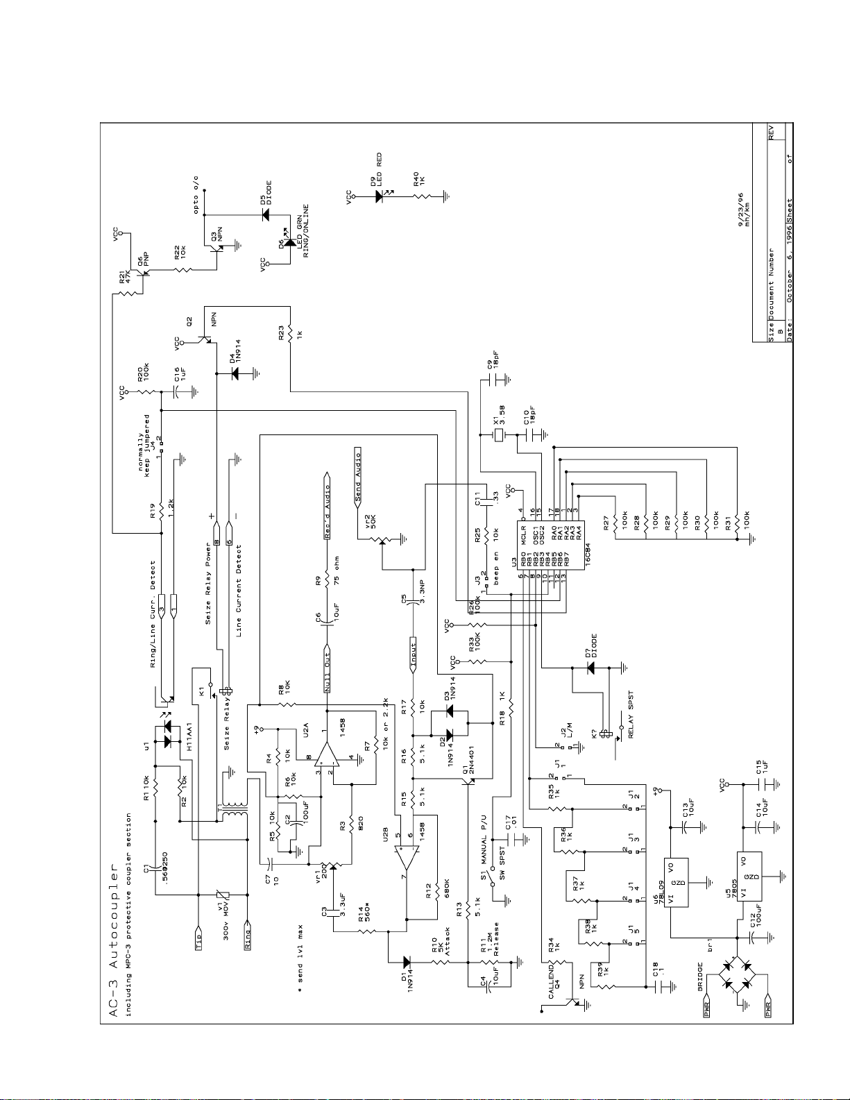
AC-3 SCHEMATIC DIAGRAM

8
RINGS, BEEPS, AND SUCH
Changing which ring the AC-3 answers on is accomplished by moving the ring set jumper J1. The unit
comes factory set for two rings. The five positions of J1 are marked 1-5. If the jumper is completely
removed the unit will answer after ten rings. You must re-initialize the microprocessor by pulling the
power after changing this jumper.
To disable the AC-3's beep upon pickup, remove the beep enable jumper, labelled "Beep En.," near the
green LED.
To make the AC-3's auxiliary relay (K2) operate in a latched fashion (for the duration of the call) remove
the "Aux L/M" jumper located between U3 (the microprocessor) and J1, the ring-select jumper pins. Be
sure to smirk at the goofed silk screen incorrectly identifying this jumper as J3. It should have said J2.
The Aux relay is factory set to operate in momentary mode at pickup.
If you intend to monitor the line-current / ring optocoupler's open-collector output AND control when
it is presented to the microprocessor for signalling, remove Jumper J4, beside the RJ-11 jack. For
normal Autocoupler operation this jumper MUST be left ON. This jumper is accessible with the AC-3's
top on.
Changing the ring select, beep enable, and Aux relay mode jumpers requires removing the top cover of
the AC-3's enclosure.
To remove the top cover of the AC-3, first remove the optional rack mount panel (if so equipped) then
press the Red and Green LEDs on the front panel in with your fingertip so the fronts of their lenses are
even with the front of the case. Next remove the four (keps) nuts from the case and remove the top half.
You now have access to the main board.
The board layout on page four gives you the locations of the jumper positions noted above, and more.
Reassembling the case: Gently pull the two, front-panel LEDs straight forward about 1/4" so the flat
edges (where the leads come out) are roughly even with front edge of the bottom plate. Next angle the
fronts of the leds down just slightly, somewhere around 30 degrees. Place the top of the box on with the
front angled down to roughly match the angle of the leds and position it so the LEDs enter their round
holes in the front edge of the box. Gently move the box-top into position over the front two 6-32 studs
(at each side of the bottom plate) and lower the top onto the front studs first then the back. With just a
little luck your LEDs will have made it through the front panel with no problem. If one or both of them
don't quite make it through, take a long, thin, regular screwdriver and gently push them through from
behind; you can do this with the top on. Replace the (keps) nuts that hold the top in place and reattach
your rack plate, if so equipped.

9
APPENDIX A
What can I do if the phone company does not provide an end of call line reversal (CPC)?
Depending upon the type of service that you intend to use the coupler for, there are a few options:
1. If your telephone line does provide dial-tone or a busy (or reorder) signal after the calling party
hangs up the the easiest and best cure is to buy a CP-1 call progress decoder board and install it in
your AC-3. The CP-1 "listens" to the incoming audio stream and detects the presence of dial-tone or
busy/reorder signals. When they are detected the CP-1 forces the AC-3 to hang up.
2 If you are going to use the coupler as an outgoing message center (concert line, etc.) and if the
associated device that has an end of message (EOM) output (like the secondary or tertiary tones of
many cart decks) you could use those outputs to force the coupler to hang up the phone. If you don’t
have an EOM output available, you may still be able to provide the same function with the device’s
ready output. You would connect the n/c contacts of a relay slaved to the cart deck's EOM output to
the ring thru connections on the AC-3's terminal strip. A soon as the relay contacts open, the AC-3
will hang up and it will not respond to an incoming ring again until the circuit is closed again. Note,
that means that a ready indicator from a machine must be made momentary in order to work. There
are several ways to do this. If you want to know more, contact us.
3. If your messages are all of the same length, you can build a simple timer from a 555 or other
device which will output a +5V pulse (refernced to the pcb ground) to the 'c' pin of the ring thru
terminals after the appropriate interval.
The ComboLok option provides you with secured access and two sets of form-c
contacts that are activated only after the unit is unlocked with the user-settable
password. Field retrofit with the ComboLok option requires some simple
component soldering and the replacement of the microcontroller (U3).
Contact your CircuitWerkes dealer for pricing on these options.
OTHER OPTIONS AVAILABLE
Rack Mount your AC-3 with the RM-01 from CircuitWerkes.

10
REPAIR OR SERVICE INFORMATION
In the event of the need for service or repair, call CircuitWerkes at (352) 335-6555 for a Return
Merchandise Authorization number (RMA). Then carefully package the unit along with a note of the
problem and send it to the address below. Clearly indicate the RMA number on the outside of the
box. We cannot accept returns without an RMA. Be sure to include a note with a brief description
of the problem, your address (not a PO box), telephone number and best time to call.
CircuitWerkes
ATTN: CUSTOMER SERVICE DEPT.
3716 SW 3RD PL
GAINESVILLE, FL 32607
CIRCUITWERKES LIMITED WARRANTY
This product is warranted against defects for two years from date of purchase from CircuitWerkes and CircuitWerkes
authorized distributors. Within this period, we will repair it without charge for parts and labor. Proof of purchase-date
required. Warranty does not cover transportation costs, or a product subjected to misuse, accidental damage, alteration
(except as authorized by CircuitWerkes), improper installation, or consequential damages.
Exceptasprovidedherein,CircuitWerkesmakesnowarranties,expressorimplied,includingwarrantiesofmerchantability
and fitness for a particular purpose. Some states do not permit limitation or exclusion of implied warranties; therefore,
the aforesaid limitation(s) or exclusion(s) may not apply to the purchaser. This warranty gives you specific legal rights
and you may also have other rights which vary from state to state.
Table of contents


