Circutor RECmax Lpd User manual
INSTRUCTION MANUAL
Earth leakage circuit breaker with automatic
re-closing system
RECmax Lpd
(M98252901-03-18A)

2
RECmax Lpd
Instruction Manual
3
Instruction Manual
RECmax Lpd
SAFETY PRECAUTIONS
DANGER
Warns of a risk, which could result in personal injury or material damage�
ATTENTION
Indicates that special attention should be paid to a speci c point.
Follow the warnings described in this manual with the symbols shown below�
If you must handle the unit for its installation, start-up or maintenance, the following
should be taken into consideration:
Incorrect handling or installation of the unit may result in injury to personnel as well as damage
to the unit� In particular, handling with voltages applied may result in electric shock, which may
cause death or serious injury to personnel� Defective installation or maintenance may also
lead to the risk of re.
Read the manual carefully prior to connecting the unit� Follow all installation and maintenance
instructions throughout the unit’s working life� Pay special attention to the installation stan-
dards of the National Electrical Code�
Refer to the instruction manual before using the unit
In this manual, if the instructions marked with this symbol are not respected or carried out correctly, it can
result in injury or damage to the unit and /or installations�
CIRCUTOR, SA reserves the right to modify features or the product manual without prior noti cation.
DISCLAIMER
CIRCUTOR, SA reserves the right to make modi cations to the device or the unit speci ca-
tions set out in this instruction manual without prior notice�
CIRCUTOR, SA on its web site, supplies its customers with the latest versions of the device
speci cations and the most updated manuals.
www�circutor�com
CIRCUTOR, recommends using the original cables and accessories that are
supplied with the device�

4
RECmax Lpd
Instruction Manual
CONTENTS
SAFETY PRECAUTIONS ���������������������������������������������������������������������������������������������������������������������������������������3
DISCLAIMER ����������������������������������������������������������������������������������������������������������������������������������������������������������3
CONTENTS�������������������������������������������������������������������������������������������������������������������������������������������������������������4
REVISION LOG�������������������������������������������������������������������������������������������������������������������������������������������������������5
SYMBOLS���������������������������������������������������������������������������������������������������������������������������������������������������������������5
1�- VERIFICATIONS UPON RECEPTION ��������������������������������������������������������������������������������������������������������������6
2�- DESCRIPTION OF THE PRODUCT������������������������������������������������������������������������������������������������������������������6
3�- INSTALLING THE DEVICE �������������������������������������������������������������������������������������������������������������������������������7
3�1�- PRELIMINARY RECOMMENDATIONS ����������������������������������������������������������������������������������������������������7
3�2�- INSTALLATION �����������������������������������������������������������������������������������������������������������������������������������������8
3�2�1�- MEASUREMENT OF THE EARTH LEAKAGE CURRENT I������������������������������������������������������������8
3�3�- TERMINALS OF THE DEVICE������������������������������������������������������������������������������������������������������������������9
3�4�- CONNECTION DIAGRAMS ��������������������������������������������������������������������������������������������������������������������10
3�4�1�- MEASUREMENT OF SINGLE-PHASE NETWORK: RECmax Lpd 2-POLE�����������������������������������10
3�4�2�- MEASUREMENT OF THREE-PHASE NETWORK: RECmax Lpd 4-POLE ������������������������������������ 11
3�5�- DISCONNECTION OF THE DEVICE ������������������������������������������������������������������������������������������������������12
4�- OPERATION ���������������������������������������������������������������������������������������������������������������������������������������������������13
4�1�- OPERATING PRINCIPLE ������������������������������������������������������������������������������������������������������������������������13
4�2�- DESCRIPTION OF THE DEVICE ������������������������������������������������������������������������������������������������������������13
4�3�- KEYBOARD FUNCTIONS�����������������������������������������������������������������������������������������������������������������������14
4�4�- DISPLAY ��������������������������������������������������������������������������������������������������������������������������������������������������15
4�5�- LED INDICATORS �����������������������������������������������������������������������������������������������������������������������������������16
4�6�- INPUTS ���������������������������������������������������������������������������������������������������������������������������������������������������17
4�7�- OUTPUTS �����������������������������������������������������������������������������������������������������������������������������������������������17
4�8�- RESET LEVER AND MANUAL LOCKING ���������������������������������������������������������������������������������������������18
4�9�- NORMAL OPERATING STATUS�������������������������������������������������������������������������������������������������������������18
4�10�- TRIP STATUS ����������������������������������������������������������������������������������������������������������������������������������������19
4�10�1�- AUTOMATIC RECLOSING IS POSSIBLE ��������������������������������������������������������������������������������������19
4�10�2�- AUTOMATIC RECLOSING IS NOT POSSIBLE������������������������������������������������������������������������������20
5�- DISPLAY ����������������������������������������������������������������������������������������������������������������������������������������������������������22
5�1�- NORMAL OPERATING STATUS�������������������������������������������������������������������������������������������������������������22
5�2�- TRIP STATUS ������������������������������������������������������������������������������������������������������������������������������������������23
5�2�1�- EARTH LEAKAGE PROTECTION TRIP ������������������������������������������������������������������������������������������23
5�2�2�- CIRCUIT BREAKER TRIP�����������������������������������������������������������������������������������������������������������������24
6�- CONFIGURATION ������������������������������������������������������������������������������������������������������������������������������������������25
6�1�- EARTH LEAKAGE PROTECTION����������������������������������������������������������������������������������������������������������25
6�1�1�- ACTIVATION DELAY �������������������������������������������������������������������������������������������������������������������������25
6�1�2�- SENSITIVITY CURRENT, IΔN�����������������������������������������������������������������������������������������������������������������������������������������26
6�2�- AUTOMATIC RECLOSING����������������������������������������������������������������������������������������������������������������������27
6�2�1�- SRD: EARTH LEAKAGE RECLOSING SEQUENCE ����������������������������������������������������������������������27
6�2�2�- SRM: CIRCUIT BREAKER RECLOSING SEQUENCE ��������������������������������������������������������������������28
6�2�3�- RSTC: PARTIAL METER RESETTING���������������������������������������������������������������������������������������������29
6�2�4�- POLT: CONFIGURATION OF TRIP OUTPUT�����������������������������������������������������������������������������������29
6�2�5�- FREQ: NOMINAL FREQUENCY�������������������������������������������������������������������������������������������������������30
6�2�6�- FACT: FACTORY CONFIGURATION������������������������������������������������������������������������������������������������31
6�3�- LOCKING THE CONFIGURATION ���������������������������������������������������������������������������������������������������������31
6�3�1�- PHYSICAL LOCKING �����������������������������������������������������������������������������������������������������������������������31
6�3�2�- PROGRAM LOCKING�����������������������������������������������������������������������������������������������������������������������31
7�- TECHNICAL FEATURES ��������������������������������������������������������������������������������������������������������������������������������33
8�- TECHNICAL SERVICE������������������������������������������������������������������������������������������������������������������������������������36
9�- WARRANTY�����������������������������������������������������������������������������������������������������������������������������������������������������36
10�- CE CERTIFICATE������������������������������������������������������������������������������������������������������������������������������������������37
5
Instruction Manual
RECmax Lpd
REVISION LOG
Table 1: Revision log�
Date Revision Description
10/13 M98252901-03-13A Initial Version
11/13 M98252901-03-13B Modications in the characteristics of earth leakage transformer.
12/17 M98252901-03-17A New manual design
05/18 M98252901-03-18A Changes in the following sections:
3�3� - 3�4� - 4�7� - 4�9� - 4�10�
Note: The images of the devices are for illustrative purposes only and might differ from the
original device.
SYMBOLS
Table 2: Symbols�
Symbol Description
In compliance with the relevant European directive�
The device complies with the 2012/19/EC European directive� Do not dispose of the device
in a household waste container at the end of its useful life� Observe the local electronic
device recycling regulations�
Direct current�
~Alternating current�
6
RECmax Lpd
Instruction Manual
1�- VERIFICATIONS UPON RECEPTION
The following must be checked upon reception of the device:
a) The device has been supplied according to the specications in your order.
b) The device has not been damaged during transport�
c) Perform an external visual inspection of the device before connecting it�
d) Check that it has been supplied with the following:
- An installation guide�
- 3 Plug-in terminals,
- 1 Adhesive label with a warning message�
Immediately contact the carrier and/or CIRCUTOR's after-sales service if
you detect any problem in the device upon reception�
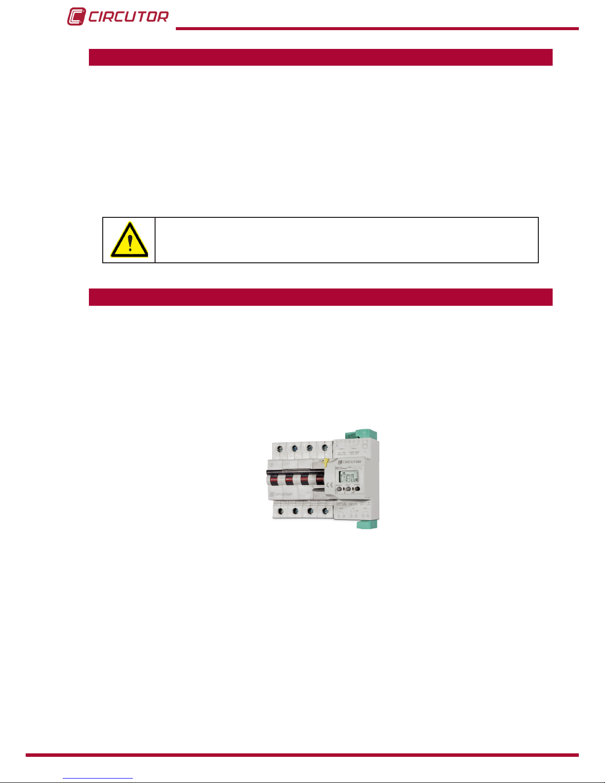
2�- DESCRIPTION OF THE PRODUCT
The RECmax Lpd protects against over-currents and is based on an ultra-immunised circuit
breaker and earth leakage protection system, with breaking capacity at full load and automatic
re-closing control�
The device comprises a 2 or 4-pole circuit breaker, which is mechanically connected to a motor
and a tripping device controlled by an earth leakage relay� It provides protection against leak-
age currents and has an automatic re-closing control� The RECmax Lpd requires an external
earth leakage transformer (with suitable sensitivity), which is supplied separately�
There are 2 models available:
RECmax Lpd 2-pole, for single-phase installations�
RECmax Lpd 4-pole, for three-phase installations�
The device features:
- Inputs for the measurement of earth leakage current�
- 3 keys that can be used to browse the various screens and program the device�
- 2 Indicator LEDs�
- LCD Display, to view the parameters�
- 1 inputs for remote control�
- 2 alarm outputs�
- 1 output to indicate the status of the main switch�
7
Instruction Manual
RECmax Lpd
3�- INSTALLING THE DEVICE
3�1�- PRELIMINARY RECOMMENDATIONS
The operators using and handling the device must follow the safety measures
established in the country where the device will be used to guarantee its safe
operation, using personal protective equipment if needed�
The RECmax Lpd device must be installed by authorised and qualied staff.
Disconnect the device from the mains and disconnect the measuring devices before handling,
changing the connections of or replacing the device� Handling the device while it is connected
is hazardous to people nearby�
The cables must be in perfect working order to prevent accidents or injuries to people and/or
damage to the facilities/installations�
Limit the operation of the device to measuring the specied current or voltage values.
The manufacturer of the device shall not be held responsible for any damage resulting from the
user or installation company failing to observe the warnings and/or recommendations indicated
in this manual nor for any damage resulting from the use of non-original products or accesso-
ries or those from other brands�
Inspect the device before using it� Make sure that there are no cracks and that the housing is
intact�
Do not use the device to take measurements if you detect an anomaly or malfunction�
Check the environment in which the device is installed before taking a measurement� Do not
use the device to take measurements in dangerous, explosive, wet or damp environments�
Disconnect the device from the mains and from the power supply (both the device
and its measuring system) before performing any maintenance work, repairs or
handling any of the connections of the device�
Contact the after-sales service if you detect that the device is not working prop-
erly�

8
RECmax Lpd
Instruction Manual
3�2�- INSTALLATION
While the device is connected, the terminals, opening the cover or removing el-
ements can expose parts that are hazardous to the touch� The device must not
be used until the installation process is complete�
The RECmax Lpd must be installed inside an electric panel or enclosure and mounted on a
DIN rail 46277 (EN 50022)�
The device has connection indicator LEDs, indicating the presence of voltage� Even if these
LEDs are not on, the user must still verify that the device is disconnected from all power sup-
plies�
The device’s auxiliary supply must be protected with fuses or protection elements appropriate
for the power supply range and consumption� Preferably the protection should consist of a small
circuit breaker allowing the disconnection of the unit from the power supply in case of servicing�
3�2�1�- MEASUREMENT OF THE EARTH LEAKAGE CURRENT IΔ
The earth leakage current must be measured using the WG/WGS/WGC earth leakage trans-
formers from CIRCUTOR�
The transformer terminals which should be connected to terminals 7-8 of the RECmax Lpd
(Table 4), are :
Table 3: Earth leakage transformer terminals�
Earth leakage transformer to connect in the RECmax Lpd
Model Terminals
WGC S1 - S2
WGS - WG 1S1 - 1S2
The external earth leakage transformer is necessary for the device to operate
correctly� Even if its installation only appears linked to the correct working of
the earth leakage protection, failing to install it will affect other functions of
the device, such as the reclosing and display of parameters on the RECmax
Lpd display�
An incorrect or faulty connection of the earth leakage transformer means
loss of the earth leakage protection and possible risk of electric shock�
When using the WG/WGS earth leakage transformers, the 2S1-2S2 termi-
nals should not be connected to the RECmax Lpd nor should be short-cir-
cuited� They should be left at open circuit�
In case of a faulty connection of the earth leakage transformer or if this transformer is not
compatible with the RECmax Lpd, the screen shown in Figure 1 will appear�
9
Instruction Manual
RECmax Lpd
REC
Figure 1: Error in the connection of the earth leakage transformer�
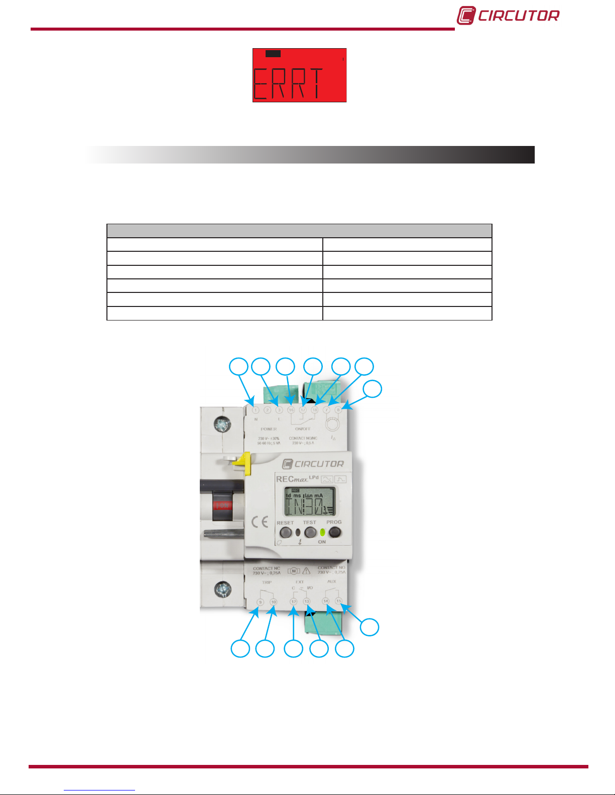
3�3�- TERMINALS OF THE DEVICE
The RECmax Lpd terminals are distributed between the upper and lower face of the device�
Table 4:List of RECmax Lpd terminals�
Terminals of the RECmax Lpd device
1, 3: Power supply 13: EXT, remote control input
7: Input S1 for measuring the earth leakage current IΔ 14: AUX, AUX output (Common)
8: Input S2 for measuring the earth leakage current IΔ 15: AUX, AUX output (NO)
9: TRIP, TRIP output (Common) 16: ON/OFF, ON/OFF output (Common)
10: TRIP, RIP output (NC) 17: ON/OFF, ON/OFF output (NC)
12: EXT, remote control input 18: ON/OFF, ON/OFF output (NO)
1 3 16 17 18
8
7
9 10 12 13 14
15
Figure 2:RECmax lpd terminals�
10
RECmax Lpd
Instruction Manual
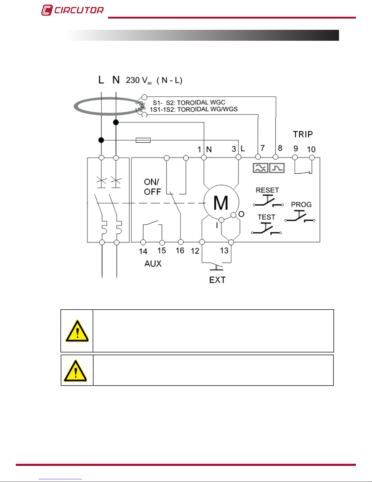
3�4�- CONNECTION DIAGRAMS
3�4�1�- MEASUREMENT OF SINGLE-PHASE NETWORK: RECmax Lpd 2-POLE
17 18
Figure 3: Measurement of single-phase network: RECmax Lpd 2-pole�
The EXT input enables the motorised switch to be controlled remotely (opening
and closing)� The input is activated when terminals 12-13 are short circuited
with an external voltage-free contact, for example a button� Said input acts
as an edge-triggered bistable T-type input, i�e�, the status of the main switch
changes on each pulse, if the switch is open it closes, if it is closed it opens�
The N-L auxiliary power supply (terminals 1-3) may be external to the installa-
tion to be protected, but in no case it must be connected downstream from the
main switch�
11
Instruction Manual
RECmax Lpd
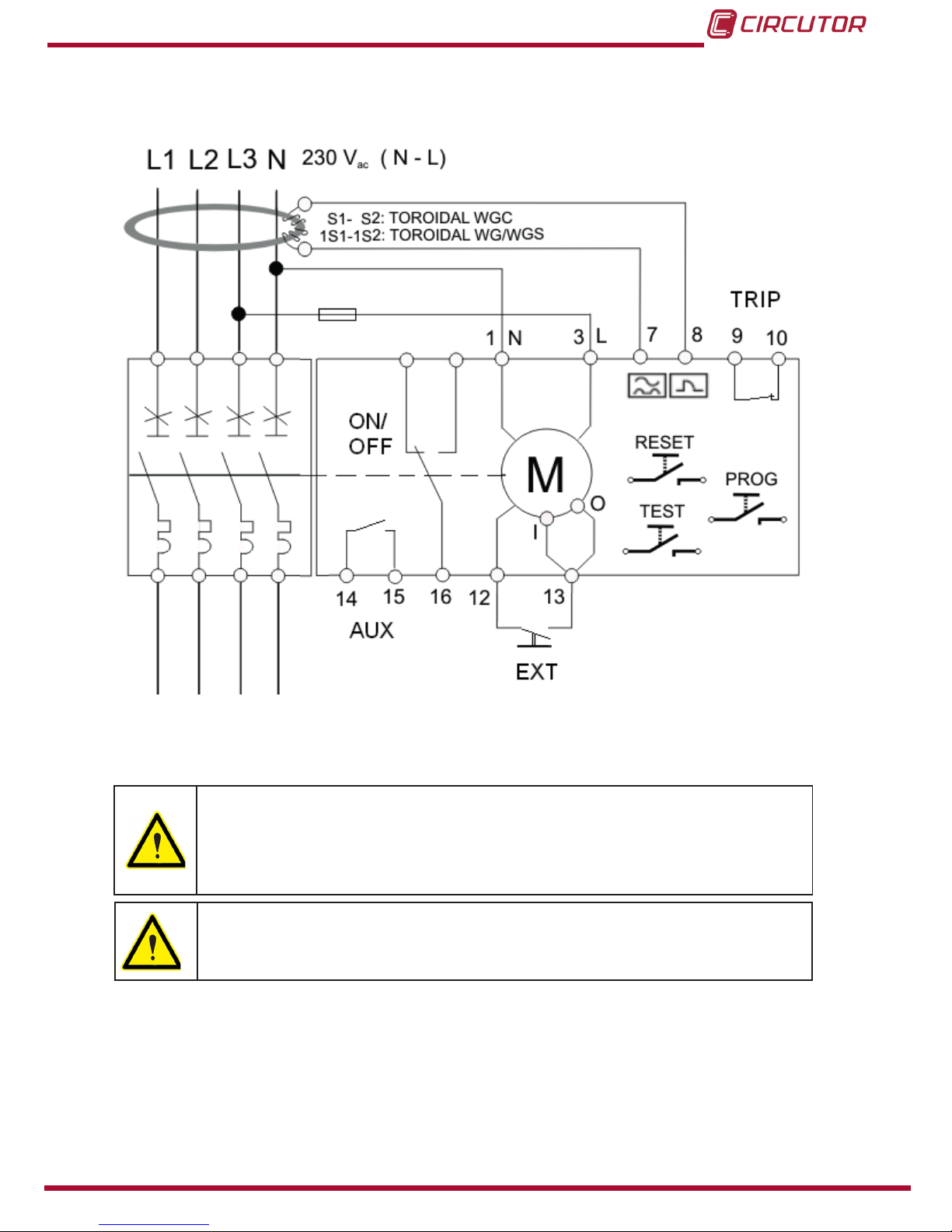
3�4�2�- MEASUREMENT OF THREE-PHASE NETWORK: RECmax Lpd 4-POLE
17 18
Figure 4: Measurement of three-phase network: RECmax Lpd 4-poles�
The EXT input enables the motorised switch to be controlled remotely (opening
and closing)� The input is activated when terminals 12-13 are short circuited
with an external voltage-free contact, for example a button� Said input acts
as an edge-triggered bistable T-type input, i�e�, the status of the main switch
changes on each pulse, if the switch is open it closes, if it is closed it opens�
The N-L auxiliary power supply (terminals 1-3) may be external to the installa-
tion to be protected, but in no case it must be connected downstream from the
main switch�
12
RECmax Lpd
Instruction Manual
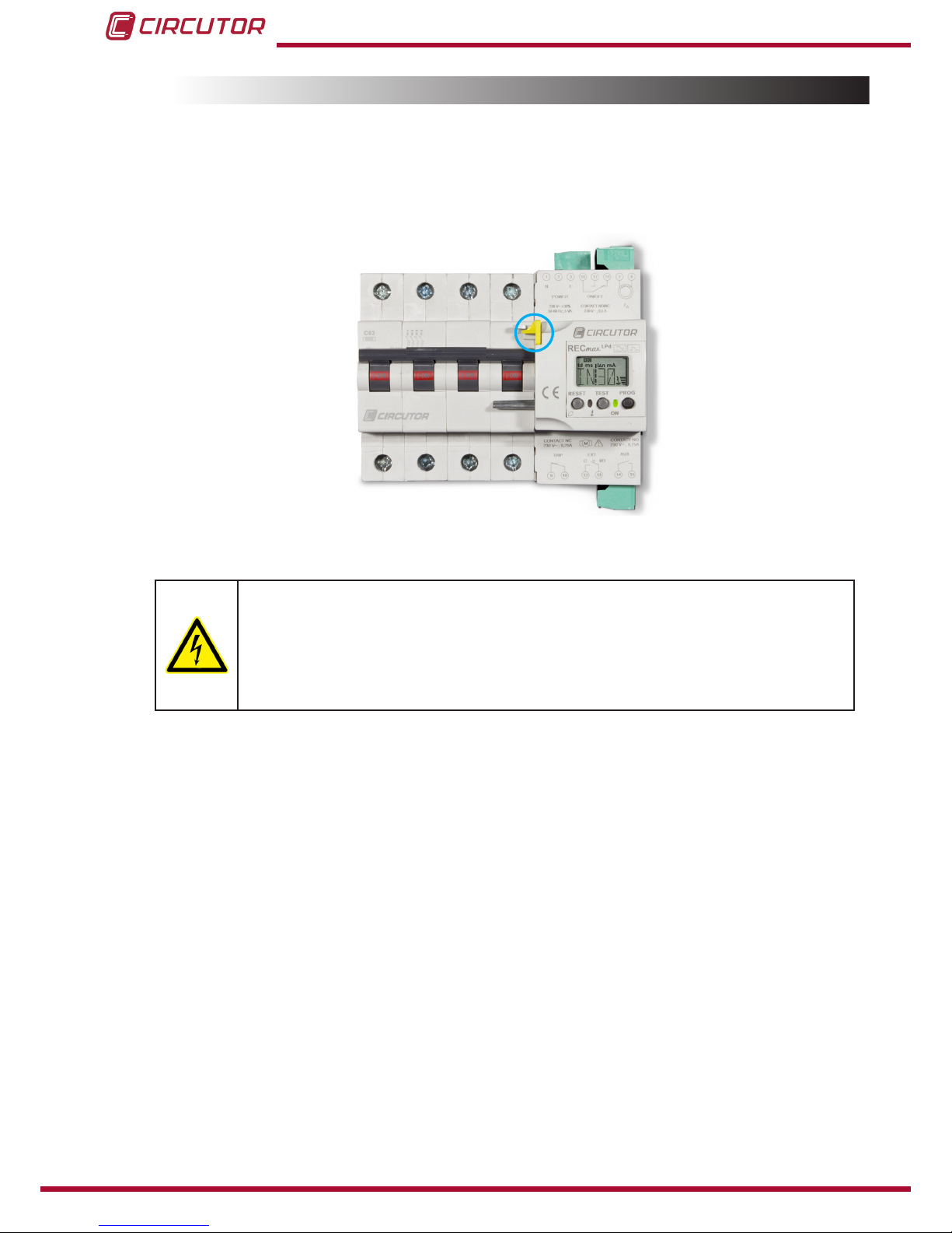
3�5�- DISCONNECTION OF THE DEVICE
If after wiring the RECmax Lpd you decide to have the protected line disconnected, you must
disconnect the device manually by pushing the contact lever of the switch downwards and
moving the mechanical lock (yellow sealable catch Figure 5) upwards� This eliminates any pos-
sibility of accidental reclosing
Figure 5: Mechanical lock�
Never manually lower the circuit breaker without previously enabling the me-
chanical lock (moving the yellow sealable catch, Figure 5, upwards)� This pre-
vents accidental reclosing while handling the installation� On doing this, al-
though the green LED is not on, the unit remains connected to the upstream
auxiliary power supply and therefore precautions should be taken to avoid
touching parts with voltage�
13
Instruction Manual
RECmax Lpd
4�- OPERATION
4�1�- OPERATING PRINCIPLE
RECmax Lpd is a device for protecting single-phase or three-phase electrical installations of
up to 63 A in which a high continuity of electrical service must be guaranteed�
The device has an automatic reset system after a trip, so it reconnects on its own after a period
of time, with the installation recovering power without human operator intervention�
The basic functions of the RECmax Lpd are:
Earth leakage protection (protecting people against electric shock and property against the
risk of re)
Protection against overloads and short-circuits with a circuit breaker�
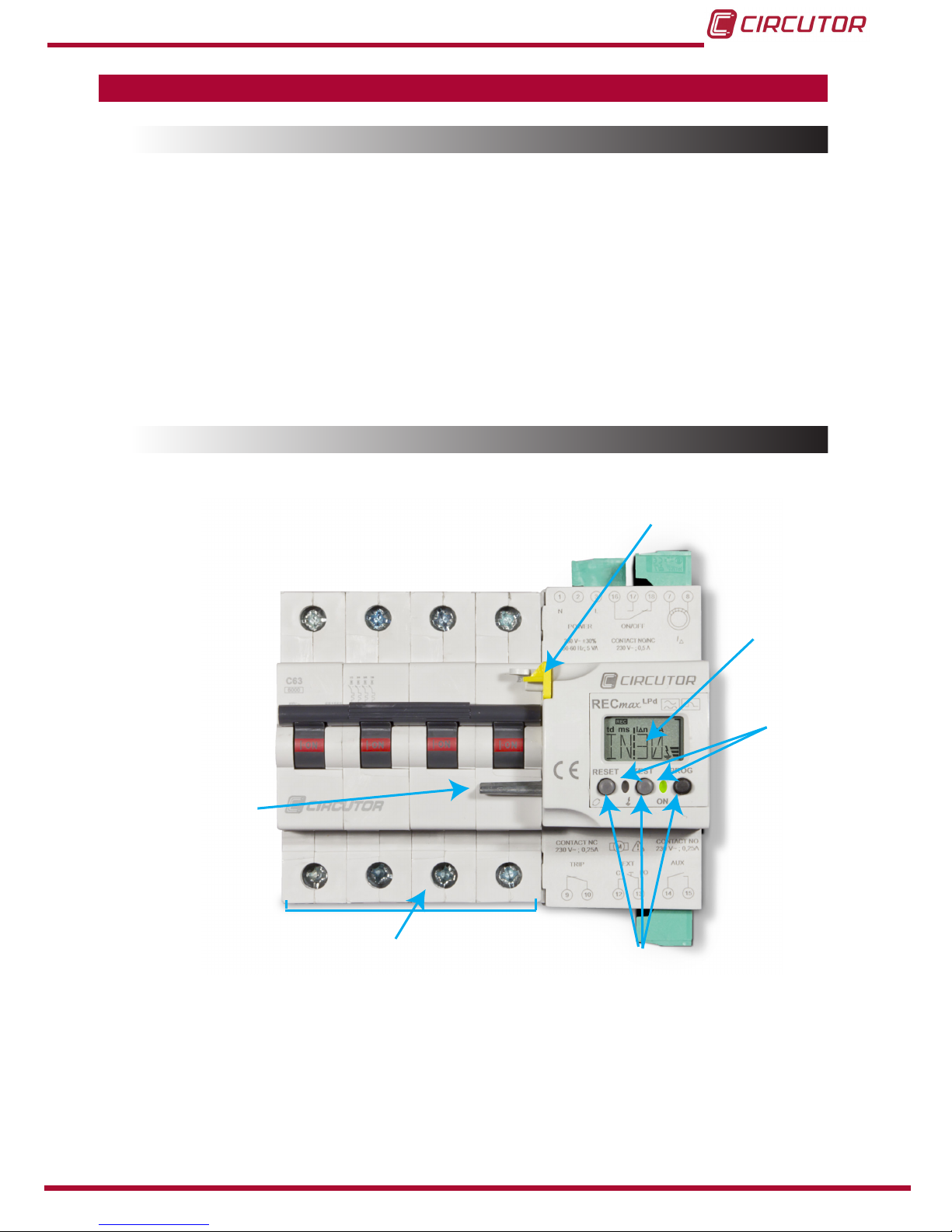
4�2�- DESCRIPTION OF THE DEVICE
Reset lever
Main switch
Manual locking
Display
LEDs
Keyboard
Figure 6: General description of the device�

14
RECmax Lpd
Instruction Manual
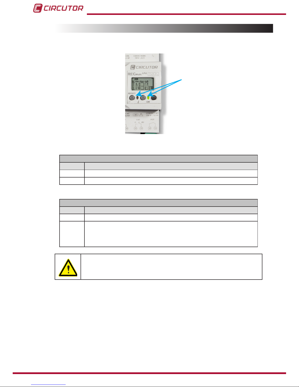
4�3�- KEYBOARD FUNCTIONS
The RECmax Lpd has 3 keys, Figure 7:
Keyboard
Figure 7: Keyboard�
TEST, pressing this key causes a forced trip of the earth leakage protection� If the
device has already tripped, pressing does not cause any action�
Pressing the TEST key disables the automatic reclosing system, as it is
considered that the person who performs the local TEST will generate the
reset for rearming the protection�
RESET, the function of the key depends on the status of the device:
Table 5: Operation of the RESET key�
Key Operation
RESET
Normal operating status
Display of the home screen of the device with description of the rmware
model and version�
Trip status
System restart and reclosing the device�
Conguration
Browsing the setup menu�
Jumping between the different Conguration options.
PROG, the function of the key depends on how long it is pressed� The PROG key is
physically sealable, see “6.3.1.- PHYSICAL LOCKING”.
Table 6: Operation of the PROG key�
Key Operation
PROG
Short press (< 3 s)
Saves the congured values and exits the setup menu.
Long press ( > 3 s)
Accesses the setup menu

15
Instruction Manual
RECmax Lpd
4�4�- DISPLAY
The device has a backlight display with green or red light, according to the status of the device�
The backlight is green and in trip conditions it is red under normal operating conditions�
td s
A
I n
REC
+
PROG N
Figure 8: RECmax Lpd display�
The device display shows different symbols that indicate the operating status of the device:
The leakage symbol with the bars is activated when a leakage current is detected�
The number of bars is proportional to the instantaneous value of the leakage current,
scaled with respect to the trip current IΔn.
td s
A
I n
REC
+
PROG N
The REC symbol is displayed when automatic reclosing is possible�
The +symbol indicates that the TRIP output is congured for positive safety.
td s
A
I n
REC
+
PROG N
The PROG symbol is displayed on the setup screens of the device�
td
mAI n
REC
td s
A
I n
REC
+
PROG N
16
RECmax Lpd
Instruction Manual
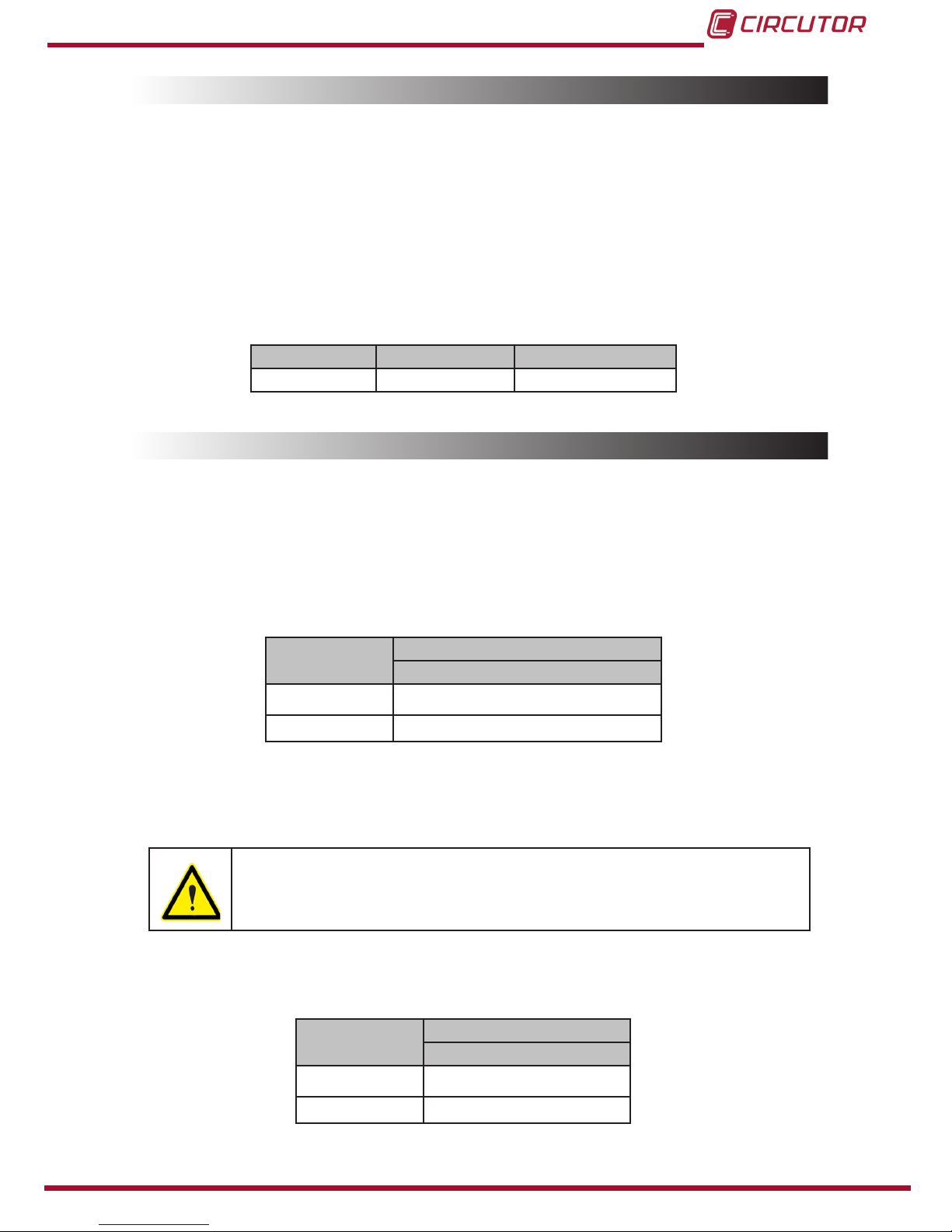
4�5�- LED INDICATORS
The device has 2 indicator LEDs, Figure 9�
LEDs
Figure 9: RECmax Lpd LED indicators�
Table 7: Description of the LEDs: Normal operating status�
Normal operating status
LED Description
Green On: Powered device�
Red Off
Table 8: Description of the LEDs: Trip status�
Trip status
LED Description
Green Off
Red
Flashing:
The device is waiting for the time needed for an automatic reclosing attempt�
Permanent:
Automatic reclosing is not possible�
The ashing or simultaneous switching on of the Red and Green LEDs
indicates that the device is not working correctly, either because of an in-
trinsic problem in the device or due to improper installation�
Note: One of the most frequent causes of improper installation is that the earth leakage
transformer has not been connected. In that case the Red LED comes on and the Green LED
ashes rapidly.
17
Instruction Manual
RECmax Lpd
4�6�- INPUTS
The RECmax Lpd has one key:
EXT input (terminals 12 and 13 in Table 4) enables the remote control of the main
switch, trip or reset of the switch depending on its status�
The input is activated when terminals 12-13 are short circuited with an external contact
(voltage-free), for example a button� EXT input acts as an edge-triggered bistable, T-type
input, i�e�, the status of the main switch changes on each pulse, if the switch is open it
closes, if it is closed it opens�
Table 9: Inputs�
Inputs Type Activation mode
EXT Voltage-free 200 ms pulses
4�7�- OUTPUTS
The RECmax Lpd has three outputs:
TRIP locking alarm (terminals 9 and 10 in Table 4) indicates that the device is locked,
i�e� that it cannot be automatically reclosed and needs a manual or external reset to re-
cover its normal operation�
Table 10: TRIP locking alarm�
Automatic
reclosing
TRIP locking alarm
Contact 9 - 10
Open
XClosed
Note: The TRIP locking alarm has the Positive safety Conguration; loss of power is
treated as an alarm. This type of operation can be congured, see “6.2.4.- POLT: CON-
FIGURATION OF THE TRIP OUTPUT”�
If congured without positive safety and the device loses power, the
device may be locked and the TRIP output won't be activated�
AUX fault alarm (terminals 14 and 15 in Table 4) indicates whether there is any power
or not�
Table 11: AUX fault alarm�
Power supply AUX fault alarm
Contact 14 - 15
Closed
XOpen

18
RECmax Lpd
Instruction Manual
Note: The contact is controlled by the internal microprocessor and therefore, if there is a
fault with the microprocessor the relay will not close.
ON/OFF output (terminals 16, 17 and 18 in Table 4) indicates status of the main
switch�
Table 12: ON/OFF output�
Main
switch
ON/OFF output
Contact 16 - 17 Contact 16 - 18
Closed Open Closed
Open Closed Open
4�8�- RESET LEVER AND MANUAL LOCKING
The device has a reset lever (see Figure 6), its default position is down� In case of reclosing,
the motor lever is raised actuating the switch� After the reset, the motor lever returns to its
downward position�
The device also has a manual locking system to prevent the possibility of automatic reclosing�
The lever is sealable�
Reclosing of the device can be completely prevented through manual locking� The operation
is performed by moving the reset lever downwards and moving the manual locking system
(yellow catch) to the left�
In case of manual locking, although the green LED is not ON, the device is
connected to the power supply� Therefore, there is a risk of electric shock
if the power supply is not cut off�
4�9�- NORMAL OPERATING STATUS
In normal operating conditions, powered device and without tripping, the status of the device is
shown in Table 13�
Table 13: Normal operating conditions�
Normal operating conditions
Main
switch Reset lever Green LED Red LED
Closed
(Lever up) Down Power on Off
Display TRIP Alarm AUX Alarm ON/OFF output
Green open contact closed contact contact 16-17: open
contact 16-18: closed

19
Instruction Manual
RECmax Lpd
4�10�- TRIP STATUS
The device may be tripped due to:
Actuation of the protection due to an installation defect, whether the earth leakage
protection or protection against overloads or a short-circuit�
Manual opening of the main switch, lowering the switch lever�
Pressing of the TEST key�
External order, after the EXT remote control input�
Whatever the case, if after the trip some maintenance check or action in the
electrical installation is required, it is advisable to activate the mechanical
lock to prevent accidental reclosing during operation�
If the trip was caused by actuation of the protection, NEVER reclose the
switch manually, always do so by pressing the RESET key�
The trip gives rise to one of 2 possibilities:
Automatic reclosing is possible
Automatic reclosing is not possible
4�10�1�- AUTOMATIC RECLOSING IS POSSIBLE
Immediately after the trip, the device begins a sequence of reclosing attempts with the pro-
grammed time intervals�
In this situation the status indicators are shown in Table 14�
Table 14: Trip status: Automatic reclosing possible�
Trip status: Automatic reclosing is possible
Main
switch Reset lever Green LED Red LED
Open
(Lever down) Down Off Flashing
Display TRIP Alarm AUX Alarm ON/OFF output
Red Open Closed contact(1) Contact 16-17: closed
Contact 16-18: open
(1) If the power supply fails, the contact is open�
If the trip is caused by an earth leakage protection fault, the display will alternate between two
screens indicating the trip current and number of reclosing attempts per earth leakage relay�
(See Figure 10 and “5.2.1.- EARTH LEAKAGE PROTECTION TRIP”)

20
RECmax Lpd
Instruction Manual
mAI n
REC
PROG
N
Figure 10: Screens after an earth leakage protection trip�
If the trip is caused by a fault in the protection due to overloads or a short circuit, a screen will
appear indicating the number of reclosing attempts carried out by the circuit breaker� (See
Figure 11 and “5.2.2.- CIRCUIT BREAKER TRIP” )
REC
N
Figure 11: Screen after a circuit breaker trip�
After an automatic reclosing sequence, the partial reclosing meters restart
after 15 or 30 minutes after the last reclose, according to the value con-
gured (see “6.2.1.- SDR: EARTH LEAKAGE RECLOSING SEQUENCE” and
“6.2.2.- SRM: CIRCUIT BREAKER RECLOSING SEQUENCE”)
4�10�2�- AUTOMATIC RECLOSING IS NOT POSSIBLE
Automatic reclosing may not be possible for one of the following reasons:
1�- Reclosing has been disabled when programming the device� The display will show
the cause of the trip without the REC symbol�
The reset is only possible by modifying the Conguration of the device, see “6.2.1.- SDR:
EARTH LEAKAGE RECLOSING SEQUENCE” AND “6.2.2.- SRM: CIRCUIT BREAKER RE-
CLOSING SEQUENCE”
2�- The number of reclosing attempts has been exhausted� The display will show the
cause of the trip without the REC symbol�
In this case, the reset is only possible by pressing the RESET key or by an external order
of the EXT input�
Reclosing the device with the RESET key or the EXT input restarts the partial reclosing
meters�
3�- The device was tripped manually by pressing the TEST key� The display will show the
“TEST” text, see “5.2.3.- TRIPPING WITH THE TEST KEY”�
In this case, the reset is only possible by pressing the TEST key again�
4�- The trip was caused by the EXT remote control input� The display will show the “EXT”
text, see “5.2.4.- TRIP DUE TO EXT ON/OFF INPUT”
In this case, reclosing is only possible with another external order of the EXT remote
control input�
Other manuals for RECmax Lpd
1
Table of contents
Other Circutor Circuit Breaker manuals


